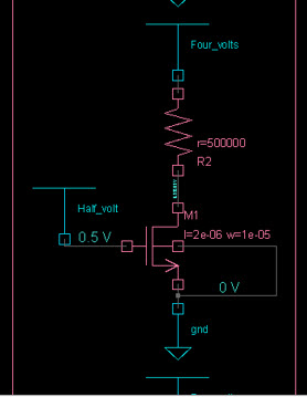
Devices that are not analog primitives but are part of the analog subcircuit are displayed in rectangular boxes in the schematic. You will not to able to descend into these subcircuits or inline subcircuit symbols in the Schematic Tracer.
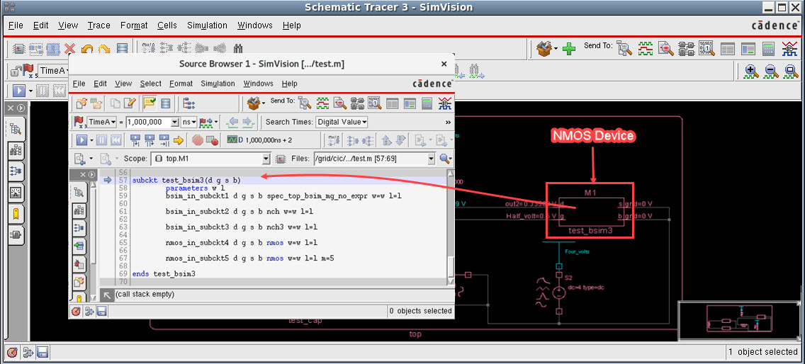
For example, the highlighted symbol in the image below is an NMOS device. It is represented in a rectangular box in Schematic Tracer. When this symbol is sent to Source Browser, the name of the subcircuit and the other details of the symbol can be found.
Perform the following steps to map these symbols into meaningful electrical symbols in SimVision MS:
- In Schematic Tracer, click the Cells menu and select Generate Cell Template.
The Generate Cell Shapes Template form appears.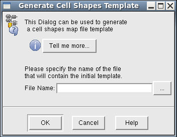
- In the File Name field, enter a name for the template file with
.mapextension. For example,analog.map. -
Click OK.
A.mapfile will be generated in the current working directory. Following is the sample of the contents of a.mapfile.cell buf shape <<unknown>> cell L2E_2 shape <<unknown>> ports {{Din input normal} {Aout output normal}} cell E2L_2 shape <<unknown>> ports {{Ain input normal} {Dout output normal}} section analog cell test_bsim3 symbol <<unknown>> ports {{d:<<unknown>> inout normal} {g:<<unknown>> inout normal} {s:<<unknown>> inout normal} {b:<<unknown>> inout normal}} cell test_cap symbol <<unknown>> ports {{p:<<unknown>> inout normal} {n:<<unknown>> inout normal}} cell vsrc symbol <<unknown>> ports {{src:<<unknown>> inout normal} {gnd:<<unknown>> inout normal}} …… endsectionThe upper section of the file represents the digital part. The analog section has a line beginning with
cellfor each subcircuit and inline subcircuit. -
Delete the digital contents from file.
-
In the analog section, replace all the
<<unknown>>symbols and ports with the built-in keywords. - Save and close the file.
- In Schematic Tracer, click Edit - Preferences.
The Preferences form is displayed.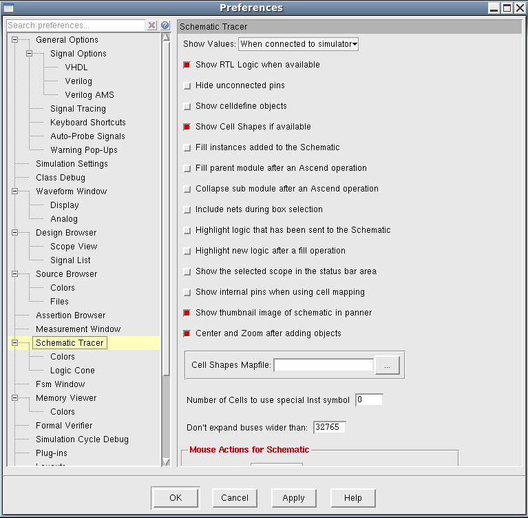
- In the Cell Shapes Mapfile field, enter the path to the
.mapfile that you saved. Alternatively, you can click ... to browse and select the file. - Click Apply.
When you re-invoke Schematic Tracer, the rectangular boxes will be modified as meaningful electrical symbols.