C
Blockage and Boundary Objects
DRD Editing and Blockage Objects
In DRD editing, objects are blocked as summarized in the following table:
Effective Width
Effective width is an attribute that you can assign to blockages. If defined, it is used as the width of the blockage when looking up the minSpacing value. DRD warns of a violation in Notify mode and prevents placement in Enforce mode if spacing between a blockage and an object is less than the minSpacing value defined for the layer. It is not necessary to have the effective width defined for all blockages. If the effective width of a blockage is not defined, the exact width of the blockage is used to look up the minSpacing value.
Using Effective Width
You can alter the effective width of a blockage object to flag or prevent spacing violations when using DRD while creating or editing certain shapes. The effective width applies to the entire blockage. The larger of the two values, the blockage effective width or the side of the non-blockage object, is used to index into the spacing table to determine the minSpacing value that applies.
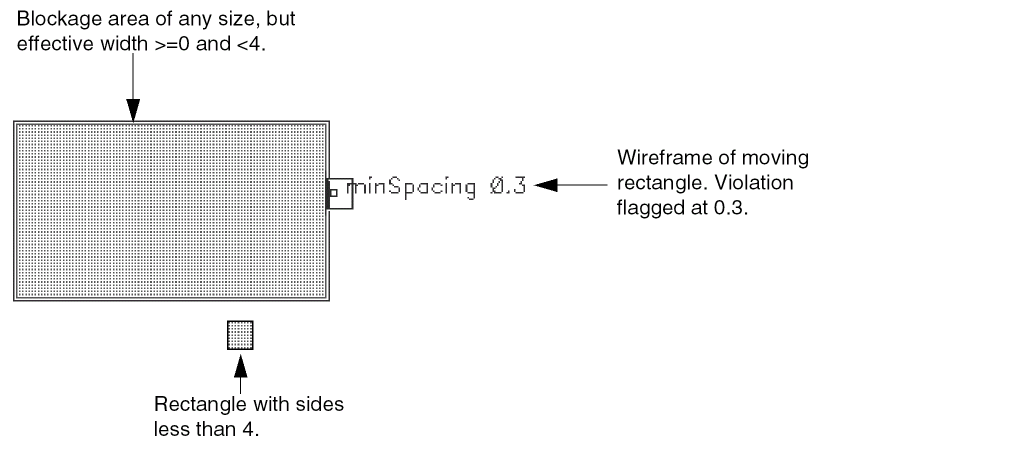
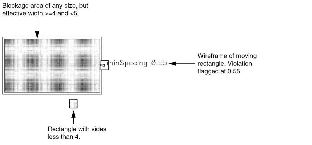
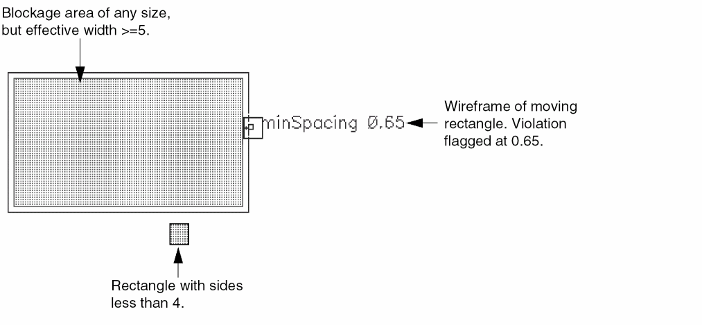
In the following example, each side of the moving rectangle is less than 4. Different spacing values apply as the effective width of the blockage changes.
Suppose that the technology file contains the following spacing values for Metal3:
( minSpacing "Metal3"
    (( "width" nil nil ))
    (
      0  0.3
      4  0.55
      5  0.65
    )
)
When the effective width of the blockage is set to a value greater than or equal to 0 and less than 4, the spacing violation is flagged at 0.3, as shown below:
When the effective width is greater than or equal to 4 and less than 5, the spacing violation is flagged at 0.55, as shown below:
When the effective width is changed from 5.0 to any number larger than 5.0, the spacing violation is flagged at 0.65, as shown below:
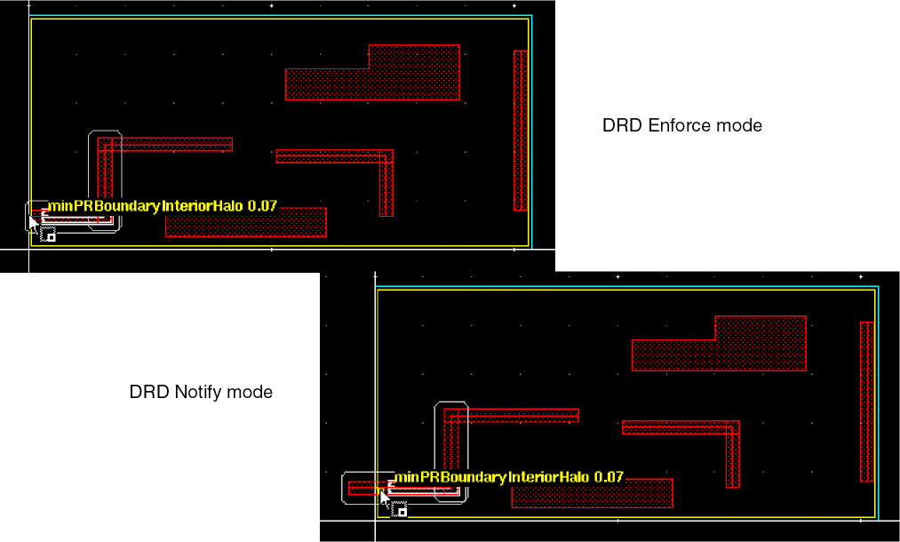
DRD Editing and PR Boundary Objects
A PR boundary is a polygonal object that defines the legal placement and routing area in a design.
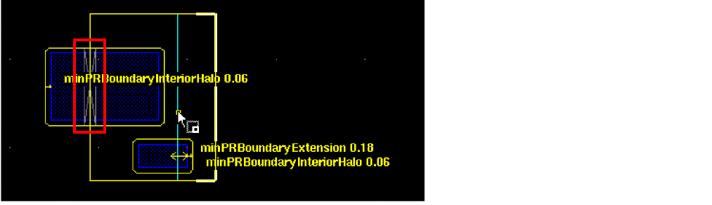
DRD provides interactive feedback when PR boundary objects are created and edited. The PR boundary spacing and extension rules defined in the technology file dictate that objects enclosed within the PR boundary object on the specified layer must be at the specified distance from it, or may extend beyond it by some minimum distance. An optional parameter 'coincidentAllowed specifies whether the spacing rules allow an object on the specified layer to coincide with the PR boundary object.
The following are examples of PR boundary spacing rules:
-
Any
metal1object enclosed within a PR boundary object must be at least 0.5 user units away from it.(
minPRBoundaryInteriorHalo "metal1" 0.5) -
Any
metal2object must either be enclosed by the PR boundary object, separated from it by at least 0.3 user units, or can coincide with an edge of the PR boundary object.(
minPRBoundaryInteriorHalo "metal2" 0.3 'coincidentAllowed) -
Any
metal2object that extends beyond the PR boundary must have an extension of at least 1.0 user units over the PR boundary.(
minPRBoundaryExtension "metal2" 1.0)
If objects already exist when the PR boundary object is created, DRD does not attempt to interactively flag errors with warnings (in Notify mode), nor does it attempt to adjust the drag point or move the objects already placed (in Enforce mode). However, if Post-Edit mode is enabled, violations, if any, are flagged after the PR boundary object has been placed. For example, if a path exists and a PR boundary is created to overlap it, the violations are flagged with post-edit markers, if DRD Post-Edit mode is enabled.
However, if a path that violates the boundary rules is subsequently created, the path is interactively checked and errors are flagged with markers, depending on the DRD mode that is currently active.
When you use the Create, Move, Stretch or any other edit command on a PR boundary object, violations are flagged as shown below. You can also see in this example the post-edit marker that was created when the PR boundary object was placed on an already existing rectangular shape.
Creating and Editing Non-PR Boundary Objects
When non-PR boundary objects are created or edited, DRD displays warnings and enforces drag point adjustment when a PR boundary object is encountered. For example, if a path segment is stretched too close to the inside edge of a PR boundary object, DRD displays warnings, and, in Enforce mode, adjusts the drag point so that the object does not violate the spacing or overlap rule.
The following objects are supported by DRD with respect to PR boundary objects:
When you use the Edit In Place or Descend command to edit objects within the hierarchy, DRD checks are performed against the PR boundary at the same hierarchical level as the object being edited, if a PR boundary exists at that level. Checking and enforcement is done through the hierarchy up to the depth specified in the DRC Options Form form.
Return to top