|
Attribute
|
Modify
|
Type
|
Description
|
|
include Generic Via Attributes.
|
|
layer1Enc
|
yes
|
float
|
List of distances from the cut edge to the edge of layer 1 in horizontal and vertical directions, in user units.
Standard vias are connections between two adjacent signal layers on the chip that are being connected. The cut layer is where the chip processing cuts away the oxide between the two adjacent signal layers to provide the connection between them. The layer enclosure via parameters specify the width and height for the rectangles on the conducting layers that lie above and beneath the cut.
Example
list("layer1Enc" '(0.25 0.75))
|
|
layer2Enc
|
yes
|
float
|
List of distances from the cut edge to the edge of layer 2 in horizontal and vertical directions, in user units.
See layer1Enc.
Example
list("layer2Enc" '(0.25 0.75))
|
|
imp1Enc
|
yes
|
float
|
List of distances from the edge of layer 1 to the edge of implant layer 1 in horizontal and vertical directions, user units.
Some technologies add implant shapes to vias between the Metal1 and Diffusion layers. The implant enclosure via parameters specify the minimum width and height for the implant that surrounds the layer.
If there are no layer offsets, the implant enclosures are centered on the cut relative to the layer enclosure. When layer offset is applied, it affects both the layer enclosure and the implant enclosure. (The layer rectangles and the implant rectangles always have a common center.)
Example
list("imp1Enc" '(0.4 0.6))
|
|
imp2Enc
|
yes
|
float
|
List of distances from the edge of layer 2 to the edge of implant layer 2 in horizontal and vertical directions, user units.
See imp1Enc.
Example
list("imp2Enc" '(0.4 0.6))
|
|
layer1Offset
|
yes
|
float
|
List of offsets for layer 1 in horizontal and vertical directions, in user units.
In cases where Layer1 and Layer2 are not aligned on the center of the cut, the layer offset via parameters specify the amount of offset between the center of the layer and the center of the cut. The offset is added to the coordinates of the corresponding rectangle, so a positive offset moves the rectangle up and to the right.
Example
list("layer1Offset" '(0.1 0.2))
|
|
layer2Offset
|
yes
|
float
|
List of offsets for layer 2 in horizontal and vertical directions, in user units.
See layer1Offset.
Example
list("layer2Offset" '(0.1 0.2))
|
|
cutSpacing
|
yes
|
float
|
List of edge-to-edge distances between cuts in horizontal and vertical directions, in user units.
When large via cuts need to be implemented as a series of small rectangles, the spacing, columns, and rows via parameters determine the number of cut rectangles and the dimensions of the entire cut grid.
cutSpacing specifies the spacing between the cuts in multiple cut vias as a vector in X and Y.
Example
list("cutSpacing" '(2.5 2.5))
|
|
originOffset
|
yes
|
float
|
List of offsets for the origin of the via in horizontal and vertical directions, in user units.
The origin of a via is the (0,0) point in the coordinates for the shapes in the via. The originOffset specifies an offset value for the origin. The effect of specifying a value for the origin offset can be viewed in two different but equivalent ways:
Subtracting that value from the origin's point, which defaults to (0, 0), without changing any of the coordinates of the other shapes in the via relative to the default origin.
Adding that value to the coordinates of every shape within the via.
Example
list("originOffset" '(0.5 0.5))
|
|
cutLayer
|
yes
|
Integer
|
Name of the cut layer.
Example
list("cutLayer" "Cont1")
|
|
cutColumns
|
yes
|
int
|
Number of columns in the array of cuts.
When large via cuts need to be implemented as a series of small rectangles, the spacing, columns, and rows via parameters determine the number of cut rectangles and the dimensions of the entire cut grid.
Example
list("cutRows" 3)
|
|
cutRows
|
yes
|
integer
|
Number of rows in the array of cut.
See cutColumns.
Example
list("cutRows" 3)
|
|
cutWidth
|
yes
|
float
|
Width of the cut layer.
The cut width, and height, via parameters determine the size of each cut rectangle. By default, the origin (the 0,0 point of the coordinates) is at the center of the cut rectangle. For vias with multiple cut rectangles, the default origin is in the center of the cut array. See originOffset to move this default.
Example
list("cutWidth" 1.3)
|
|
cutHeight
|
yes
|
float
|
Height of the cut layer.
See cutWidth.
Example
list("cutHeight" 1.4)
|
|
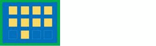
cutPattern
|
|
string
|
A string of hex characters that specify the pattern. The pattern must have an even number of hex characters. Alpha hex characters may be specified either in upper or lower case. The hex string is interpreted as an array of binary numbers. Each 1 bit in the array represents the placement of a cut. The bit stream is interpreted in row, column order. Rows and columns start in the lower left corner of the cut array. If there are not enough cuts to fill the last byte of the pattern the pattern must be padded with extra 1 bits.
Example
list("cutPattern" "4fff")
Bit pattern: 0100 1111 1111 1111
|