maxFloatingArea
Specifies the maximum area for floating metal shapes on a routing layer that are not connected to a diffusion or polysilicon gate. Similar to process antenna rules, maximum floating area rules apply only to the current layer and any lower layers (that is, all layers that have been fabricated up to the layer of interest). Maximum floating area rules can be used to avoid shorts between floating and non-floating metal wires that are caused by arcing due to charge build-up during processing steps. Applies only to routing layers.
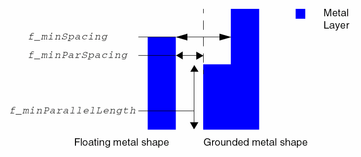
Floating metal is defined as metal on the current layer that cannot trace a path to a diffusion connection or polysilicon gate, using only same layer or lower layer metal connections.
Grounded metal is defined as metal that can connect to a diffusion connection or polysilicon gat using only same layer or lower layer metal connections.
maxFloatingArea Quick Reference
Value Type
Parameters
-
floatingAreaSpacing(LayerDualArrayTblValue) specifies minimum spacing/minimum parallel length pairs by layer. TheLayerDualArrayTblValuesyntax is:{
wheres_layerNamei_numPairs{{f_minParSpacing f_minParallelLength}…}…} -
floatingMetal(StringAsIntValue) specifies how the constraint is applied as described in the following table.
Examples
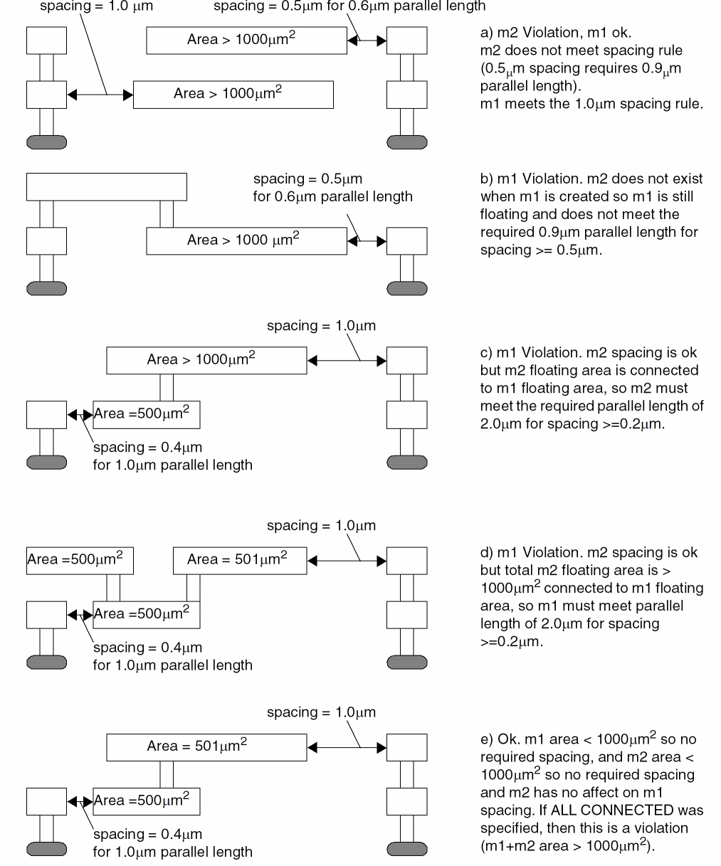
Sets the required floatingMetal and floatingAreaSpacing parameters and the maxFloatingArea constraint.
The following figure shows the behavior when the constraint is applied for this example.
Related Topics
Return to top