In this release, automatically-inserted connect modules are not visible in SimVision. As a consequence, the values returned by probing might not be what you expect. Connect modules are used when connected ports have disciplines of different domains (such as logic and electrical) so you need to be aware of the effects of connect modules that are automatically inserted, but not visible, between such ports. Note that manually inserted connect modules are visible in SimVision.
To better understand, consider the following example where the top module contains two inverters. The ports of the Dinv inverter are of the logic discipline and the ports of the Ainv inverter are electrical.
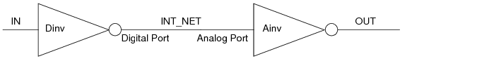
At time t, the value of IN is 0. Because there are two inverters, the value of INT_NET is 1 and the value of OUT is 0.
If you change scope into the Dinv module and probe the value of the digital port, you see that the value is 1. However, if you trace the signal to INT_NET in the top module, you find that the value depends on the discipline of that net. If INT_NET is of the logic discipline, the value is 1 as expected. But if INT_NET is of the electrical discipline, the value is a real number calculated by the analog solver. In a typical case, the value might be between 2.5 V and 5 V.
Similarly, if you trace the signal into the analog port of Ainv, where, again, the disciplines of the driver and receiver do not match, a similar issue arises.