Uses of the OpAmp Macromodel
You can use the OpAmp macromodel by doing the following:
- Defining the common specification sheet values, available in most semiconductor product catalogs
- Placing the OpAmp symbol in your schematic
- Defining the CDF parameter values and by using default values for parameters that you do not set
The OpAmp macromodel might not work as a comprehensive model. Its limitations are described here:
-
Macromodel accuracy
The OpAmp macromodel is less accurate and comprehensive than the transistor level representation, and even less accurate than the circuit measurements. -
Model scope
Specifications not defined as macromodel parameters are not modeled, including common-mode input range, noise, transient power dissipation, and output impedance. -
Temperature
Temperature effects are not implicitly included, but can be explicitly defined as an algebraic or table function. For example:offset voltage = 1m + 0.01 m * (tempdc - 25)
ORoffset voltage = TABLE(tempdc,-75,0,25,1m,125,2m)
-
Parameter independence
To a first order of accuracy, you can set the macromodel parameters independently, ignoring interactions. -
Small input bias currents
When using small input bias currents(~1E-12), decrease the simulation control variableGMIN(minimum conductance) to~1E-15(default is1.0E-12). This helps to prevent relatively large leakage currents and corresponding accuracy loss. -
Unrealistic conditions
The macromodel is particularly good for modeling the OpAmp components. Avoid the following unrealistic parameter values or extreme conditions:-
Offset voltages less than
10 mvoltsvary due to numerical errors -
The following quantities affect the accuracy of the slew rate of the macromodel in small but measurable ways:
This effect can be significant for the following examples of extreme cases:
In these situations, measure the simulated macromodel response and adjust the parameters accordingly.
-
Offset voltages less than
- Additional parameter requirements
Setup of the OpAmp Macromodel into a Design
The following figure shows an OpAmp macromodel symbol:
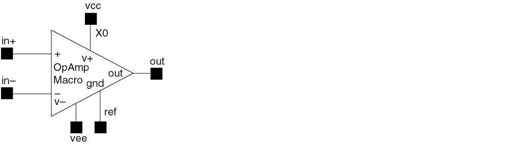
For proper operation of the macromodel, you need to connect the following six I/O pins:
OpAmp Macromodel Parameters
There are 23 parameters you can use to describe the DC, AC, and transient behavior of the OpAmp in the macromodel.
| Property | Typical Value | Description |
|---|---|---|
You define these parameters in the cell CDF description.
For example, to define the offset voltage as a simple linear function of temperature, enter the following expression as the value of the offset voltage property:
vos = 1m + 0.01m * (TEMPDC - 25)
Procurement of OpAmp Macromodel
You can obtain model parameters in several ways, depending on your application.
-
IC vendor catalog
Obtain most of the parameters from the specific amplifier catalog data sheet -
Schematics
Simulate and measure the performance parameters you want using the OpAmp transistor schematic and associated SPICE device models -
Component
Make the measurements in the lab using the OpAmp component
You can use the default values or set some reasonable values for the remaining parameters. For example, you might set parameters to some typical values (or use the defaults) when exploring your system design space before selecting a particular amplifier, then modify the values later.
OpAmp System Size
A primary reason for using macromodels in large systems is for faster simulations. These simulations are faster when compared to transistor-level simulations. These simulations are about 10 to 50 times faster for complex OpAmps containing between 30 and 100 devices. Storage requirements are also reduced using macromodels.
The fast simulation time and reduced storage requirement of smaller amplifiers (fewer than 10 devices) might not compensate for the loss of accuracy from using macromodels. However, macromodels are still useful for exploratory tuning and for protecting libraries.
Return to top