The following example introduces the concept of connect module insertion being controlled by the discipline definition. A wreal model of a very simple charge pump is used inside an analog testbench. The stimuli are created by pulse voltage sources. The output of the charge pump is connected to a simple RC filter.
The charge pump circuit drives current into the RC filter according to the input voltage levels. However, simulating this design as it would not lead to the expected simulation results. The wreal output signal of the charge pump is +/- 300u. This value is far smaller than the normal accuracy setting for R2E CM, which might be in a range of 1m. Moreover, the normal R2E CM is an electrical voltage source at the output. This does not fit to our requirements here.
module top(); electrical in1, in2, out, gnd; ground gnd; vsource #(.type("pulse"), .val0(0), .val1(3.3), .period(2n), .delay(0), .rise(100p), .fall(100p), .width(1n)) V1 (in1, gnd); vsource #(.type("pulse"), .val0(0), .val1(3.3), .period(1.87n), .delay(0.5n), .rise(100p), .fall(100p), .width(1n)) V2 (in2, gnd);
CP I1 (in1, in2, out);
capacitor #(.c(4p)) c1 (out, gnd); resistor #(.r(20k)) r1 (out, gnd);endmodule
module CP(UP, DN, Z ); input UP; // Increment Input Controls input DN; // Decrement Input Controls output Z; // Single ended output
wreal UP, DN, Z; wreal_current Z; // Disciplines could be hardcoded wreal_voltage UP, DN; // or set with the -setd option parameter real I_out = 300u; // Output Current parameter real thres = 1.5; // threshold value real iup, idn, out;
always @(UP) begin if (UP > thres ) iup = I_out; else iup = 0.0; out = iup - idn; end
always @(DN) begin if (DN > thres ) idn = I_out; else idn = 0.0; out = iup - idn; end assign Z = out;endmodule
A few things need to be done to set up the test case correctly. First, we need to define a wreal to electrical connect module with a current source output, as shown below. To simplify matters only basic conversion features have been taken into account. However, `wrealX/ZStates are not considered.
The standard E2R CM can be used for the voltage to wreal conversion at the input of the charge pump.
connectmodule R2E_current (Din, Aout); input Din; wreal Din; // input wreal \logic Din; output Aout; electrical Aout; // output electrical
parameter real tr = 10p from (0:inf); // risetime of analog output parameter real tf = tr from (0:inf);// falltime of analog output parameter real ttol_t = (tr+tf)/20 from (0:inf);// time tol of transition parameter real rout = 1M from (0:inf);// output resistance real Iout;
analog begin Iout = transition(Din, 0, tr, tf, ttol_t); I(Aout) <+ (V(Aout) / rout) - Iout; endendmodule
As said earlier, discipline settings are used to control the connect module insertion process. For this purpose, we need to specify two new discrete disciplines for the "voltage" and the "current" domain inside our wreal model.
discipline wreal_current domain discrete;enddisciplinediscipline wreal_voltage domain discrete;enddiscipline
The next step is to associate the connect modules with the appropriate discipline interfaces.
connectrules wreal_V_I;connect E2R#( .vdelta(0.1), .vtol(0.001), .ttol(1n))electrical, wreal_voltage;connect R2E_current#( .tr(0.1n), .rout(1M) )wreal_current, electrical;endconnectrules
The standard E2R/R2E connect module is used to combine the logic and electrical discipline. In this case, we need a connect module between the electrical and the wreal_voltage discipline. The default settings can be overwritten in the connect rules definition as shown above. The same applies for the R2E connect module. In addition, we use the newly defined R2E_current connect module instead of the default one.
Note that the defined current connect module is oversimplified to understand basic principles. For real usage, we need to consider more details, such as E2R_current. The current is generated from the global ground node. Thus, it is not considered in the power nets. The current source is not supply-limited, which means it would create current even if the voltage is above or below the supply range.
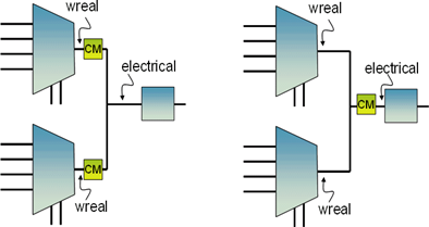
Current-based connect modules are sensitive about the placement of the CMs in the design. From the following figure, you can see that the output current of the one/two connect modules would be quite different in the two cases (assuming a wreal resolution function other than sum). To avoid these types of problems, current based CM is recommended for point-to-point connections only or you have to make sure that the resolution function sum is used for the wreal net in question.
The final step is the definition of the disciplines in the design. This is done as hard-coded assignments, as shown in the two commented lines in the charge pump definitions. The source code modification is often not appropriate. In these cases, the disciplines can be set by –setdiscipline options to xrun/xmelab. These external settings allow discipline definitions without any source code modifications. There are different scopes available for the setdiscipline option, including library, cell, and instances. For the example shown above, the following command-line run option would be appropriate. All the code examples and the discipline.vams and timescale settings are assumed to be included in the cp.vams file.
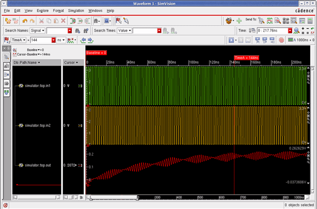
xrun cp.vams analog.scs -clean -amsconnrules wreal_V_I -setd "INSTTERM-top.I1.UP- wreal_voltage" -setd "INSTTERM-top.I1.DN- wreal_voltage" -setd "INSTTERM-top.I1.Z- wreal_current"The following figure shows the simulation results for the example. The loading of the capacitor through the charge pump output current is clearly visible.
Figure 2.2: Simulation Results for a E2R Connect Module