|
|
|||||||||
|
|
|
|
|
|
|
|
|
|
|
This chapter describes how to analyze the effects of parasitics on power net wiring, without performing a full simulation, using the Virtuoso® UltraSim™ static power grid calculator.
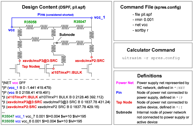
To invoke the static power grid calculator, use the -r command line option accompanied by a command file. The command file contains all of the calculator control and data filtering options. See Figure 9-1 for more information about inputs to the static power grid calculator.
Figure 9-1 Static Power Grid Calculator Input
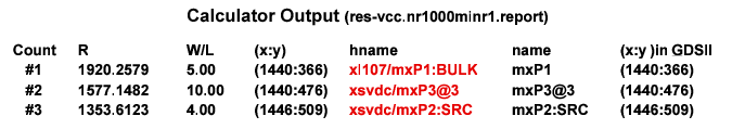
The analysis results are printed into text files (two files per net) with filename prefixes specified in the command line option. The -rout filtering routine is used to filter existing output data without running the calculator again. See static power grid calculator output in Figure 9-2.
Figure 9-2 Static Power Grid Calculator Output
|
file <file_name> |
|
|
net <net_name> |
Defines power net for calculation. Net needs to be defined in DSPF *|NET section of file. Multiple net statements are allowed. net_name is case sensitive. |
|
addnetpin <net_name> <node_name> |
Converts subnode to pin in net <net_name>. |
|
netdeletepin <net_name> <node_name> [<node_name>] |
|
|
subnode <subnode_pattern> [<subnode_pattern>] |
|
|
netdeletetap <net_name> <node_name> [<node_name>] |
|
|
ipin <pin_pattern> |
Specifies tap nodes for resistor calculation. All other tap nodes are converted to subnodes. |
|
layer0ohm <layer_name> [<layer_name>] |
|
|
layerfactor <layer_name> <scale_factor> |
Resistors with specified layer name are scaled by factor. Multiple layerfactor options are accepted. |
|
rmin <value> |
Resistors with a value less than rmin are shorted. |
|
sortby <sortkey> |
Specifies sorting method where sortkey can be r, w/l, or rw/l. |
|
report <report_options> |
Inserts -rout filtering options into command file (see <report_options> for definition). |
The -rout command line option allows you to filter results from the static power grid calculator analysis without having to rerun the calculation. The calculator reads the existing -r output files and applies filtering to the data stored in these files.
.ultrasim -rout <prefix_of_rout_file> <report_options> [+log <log_file_name> |
-log]
|
<prefix_of_rout_file> |
|
|
<report_options> |
|
|
-pat <"pattern_with_wildcards"> |
|
|
-nr <integer_value> |
|
|
-minr <double_value> |
Reports only nodes with Reff>minr |
|
-maxr <double_value> |
Reports only nodes with Reff<maxr; |
|
-xmin <value> |
|
|
-gdsmag <value> |
Specifies geometry magnification where all coordinates are multiplied by <value> if <value> is positive, or divided by <value> if <value> is negative |
|
-gdsunits <value> |
|
|
Generates a file with the name <file_name>.0.report for nodes with Reff < rth and a file with the name <file_name>.1.report for nodes with Reff >= rth. |
In the first static power grid calculator example, the following Rescalc.config command file is used:
file cell.spf
net gnd
netdeletepin gnd gnd_1
subnode gnd:* vcc:*
rmin 0.01
sortby w/l
report -nr 1000 -minr 20 -pat*.SRC -pat*.DRN
net vcc
netdeletetap vcc x1/m2:drain x1/m4:source
addnetpin vcc vcca:1
The static power grid calculator is run using the following options:
ultrasim -r Rescalc.config -o res_examp
The static power grid calculator results are printed into the following files:
- res_examp-gnd.rout (non-filtered results)
- res_examp-gnd.minr20nr1000.rout (filtered results)
- res_examp-vcc.rout (non-filtered results)
- res_examp-vcc.minr20nr1000.rout (filtered results)
ultrasim -rout res_examp-gnd -o -nr 1000 -minr 5 -maxr 1000
a filtering routine is used on the res_examp-gnd.rout output file to filter out the first 1000 resistive paths with a resistance between 5 and 1000 Ohm. The filtered results are printed into the res_examp-gnd.nr1000minr5maxr1000.report file.