


|
|
|||||||||
|
|
|
|
|
|
|
|
|
|
|
This chapter describes the following Virtuoso® UltraSim™ simulator advanced analysis methods, which include dynamic and static checks.

|
Active Node Checking detects nodes with voltage changes that exceed the user defined threshold. |
|
|
Design Checking monitors device voltages during simulation (device voltage check). |
|
|
Dynamic Power Checking reports the power consumed by each element and subcircuit in the design. |
|
|
Node Activity Analysis provides information about the nodes and monitors activity such as: voltage overshoots (VOs), voltage undershoots (VUs), maximum and minimum rise/fall times, switching activity, and half-swing flag. |
|
|
Power Analysis reports the average, maximum, and RMS current at the ports of specified subcircuits and child subcircuits for a specified level of hierarchy. |
|
|
Wasted and Capacitive Current Analysis provides information about the capacitive, static, and dynamic wasted currents in specified subcircuits. |
|
|
Power Checking performs over current and high impedance node checks. |
|
|
Timing Analysis performs setup, hold, pulse width, and timing edge checks on signals. |
|
|
Bisection Timing Optimization combines multiple iterative simulations into a single characterization. |
|
|
A period (.) is required when using SPICE language syntax (for example, .acheck). |
|
|
The acheck dv=value and .acheck dv=value syntax continues to be supported by Cadence (it has a higher capacity active node checking analysis for larger designs). |
This command is used to report the active nodes in a circuit design. A node is considered active if the change in its voltage exceeds value during the checking window. If a window is not specified, the entire simulation period is used. The active nodes are listed in netlistName.actnode and netlistName.actnodelist files. The inactive nodes are listed in netlistName.inactnode and netlistName.inactnodelist files. For the .acheck dv=value command, the nodes are reported in netlistName.actnodelist or netlistName.inactnodelist files.
|
node1 node2 ... |
|||||||
|
Defines the depth of the circuit hierarchy that a wildcard name applies to. If set to 1, only the nodes at the current level are applied (default value is infinity). |
|||||||
|
Defines the voltage change threshold for the active nodes (default is 0.1 volt). |
|||||||
|
Defines the node names to be excluded from the check (wildcards are supported). |
|||||||
|
Defines which nodes are reported.
|
Reports all the active nodes with voltage change equal to or more than 0.5V.
acheck achk1 node=[*] depth=2 dv=0.5 time_window=[10n 50n 100n 150n]
.acheck achk1 node=[*] depth=2 dv=0.5 time_window=[10n 50n 100n 150n]
Reports only the nodes in the top two hierarchical levels with voltage change equal to or more than 0.5V. In addition, the check is only performed in the time window of 10ns to 50ns and 100ns to 150ns.
acheck achk2 node=[x1.*] dv=0.5 exclude=[x1.y1.* x1.y2.*]
.acheck achk2 node=[x1.*] dv=0.5 exclude=[x1.y1.* x1.y2.*]
Checks only the active nodes in the instance x1 (and all the nodes in its child and grandchild subcircuits). However, the nodes in the instances x1.y1 and x1.y2 are excluded.
acheck achk3 node=[x1.*] dv=0.5 exclude=[x1.y1.* x1.y2.*] inactive=1
.acheck achk3 node=[x1.*] dv=0.5 exclude=[x1.y1.* x1.y2.*] inactive=1
Same as the third example, except that the inactive nodes are reported instead of the active nodes.
The Virtuoso UltraSim simulator allows you to perform a dynamic checking analysis on device voltages during a simulation by using the dcheck command. The analysis generates a report in a netlistName.dcheck file if the voltages exceed the specified voltage bounds.
To use the dcheck command, you can add it to the simulation netlist file, or place it in a command file and include the file in the simulation netlist file. The following design checking analyses are described in this section:
This command allows you to monitor metal oxide semiconductor (MOS) transistor terminal voltages during a simulation run, and generates a report if the voltages exceed the specified upper and lower bounds, or meets the specified conditions. You can exclude a subset of the instances from the voltage check using the xsubckt or xinst arguments. If a threshold or condition is not specified for dcheck in the netlist file, a warning message is issued by the Virtuoso UltraSim simulator and the dcheck command is ignored during the simulation.
Note: You can use the dcheck_err_limit option to limit the number of reported errors.
dcheck chk1 vmos model=[tt] inst=[X1] vgsu=1.0 vgsl=0.5 probe=1
dcheck chk2 vmos model=[tt2] cond=((vgs<-3 || vds>3) && l<0.2u)
dcheck chk4 vmos model=[tt4] cond=(vgs>0.5 || vgd>0.5) vdsu=1.5
dcheck chk5 vmos xinst=[I2*] xsubckt=[Reg*] vgsu=1.86
dcheck chk6 vmos inst=[I19] xinst=[I19.I19 I19.I116] vgsu=1.86
dcheck chk7 vmos subckt=[pll*] xsubckt=[osc buf] vgsu=1.86
dcheck chk8 vmos subckt=[pll*] xsubckt=[osc buf] vgsu=1.86 topnode=1
.dcheck chk1 vmos model=[tt] inst=[X1] vgsu=1.0 vgsl=0.5 probe=1
.dcheck chk2 vmos model=[tt2] cond='(vgs<-3 || vds>3) && l<0.2u'
.dcheck chk4 vmos model=[tt4] cond='vgs>0.5 || vgd>0.5' vdsu=1.5
.dcheck chk5 vmos xinst=[I2*] xsubckt=[Reg*] vgsu=1.86
.dcheck chk6 vmos inst=[I19] xinst=[I19.I19 I19.I116] vgsu=1.86
.dcheck chk7 vmos subckt=[pll*] xsubckt=[osc buf] vgsu=1.86
.dcheck chk8 vmos subckt=[pll*] xsubckt=[osc buf] vgsu=1.86 topnode=1
The command line of chk1 checks all MOSFETs using model tt in block X1. The devices that meet vgs>1 or vgs<0.5 criteria are reported. Where probe=1, all node voltages of the tt devices are probed.
The command line of chk2 checks all MOSFETs using model tt2, whether vgs<-3 or vds>3, when MOSFET length is less than 0.2 um. If the condition is met, the devices are reported.
In the command line of chk3, a conditional design analysis check is performed by the simulator, and includes nonlinear expressions. The MOSFETs that meet the condition are reported.
The command line of chk4 combines the conditional and upper/lower threshold bound checks. Only the MOSFET models that meet the specified conditions are checked.
In the command line of chk5, all MOSFETs in the netlist file are checked. The subcircuit instances with names that match I2*, instances of subcircuits with the name Reg*, and their sub-hierarchies are excluded. MOSFETs that meet the vgsu>1.86 criteria are reported.
In the command line of chk6, all MOSFETs belonging to instance I19 and its sub-hierarchy are checked. Subcircuit instances I19.I19 and I19.I116 are excluded. MOSFETs that meet the vgsu>1.86 criteria are reported.
The command line of chk7 checks all MOSFETs belonging to instances of the subcircuits with names that match pll* and their sub-hierarchies. Instances of subcircuits osc and buf are excluded. MOSFETs that meet the vgsu>1.86 criteria are reported.
The command line of chk8 checks the same thing as chk7 but reports the top-level node names rather than hierarchical terminal names into dcheck report file.
v_mvio is the maximum violation voltage within the check window.
This command allows you to monitor bipolar junction transistor (BJT) terminal voltages during a simulation run, and generates a report if the voltages exceed the specified upper and lower bounds, or meets the specified conditions. You can exclude a subset of the instances from the voltage check using the xsubckt or xinst arguments. If a threshold or condition is not specified for dcheck in the netlist file, a warning message is issued by the Virtuoso UltraSim simulator and the dcheck command is ignored during the simulation.
Note: You can use the dcheck_err_limit option to limit the number of reported errors.
|
BJT voltage check is applied to transistors matching the model name (wildcards are supported). |
|||||
|
BJT voltage check is excluded from instances of the subcircuits listed (wildcards are supported). |
|||||
|
BJT voltage check is excluded from the subcircuit instances listed (wildcards are supported). Note: The inst and xinst arguments can only be used to specify subcircuit instances, but not device instances. |
|||||
|
vbcl=volt |
Reports the condition if Vbc is less than the specified lower bound voltage value. |
||||
|
vbcu=volt |
Reports the condition if Vbc is greater than the specified upper bound voltage value. |
||||
|
vbel=volt |
Reports the condition if Vbe is less than the specified lower bound voltage value. |
||||
|
vbeu=volt |
Reports the condition if Vbe is greater than the specified upper bound voltage value. |
||||
|
vbsl=volt |
Reports the condition if Vbs is less than the specified lower bound voltage value. |
||||
|
vbsu=volt |
Reports the condition if Vbs is greater than the specified upper bound voltage value. |
||||
|
vcel=volt |
Reports the condition if Vce is less than the specified lower bound voltage value. |
||||
|
vceu=volt |
Reports the condition if Vce is greater than the specified upper bound voltage value. |
||||
|
vcsl=volt |
Reports the condition if Vcs is less than the specified lower bound voltage value. |
||||
|
vcsu=volt |
Reports the condition if Vcs is greater than the specified upper bound voltage value. |
||||
|
vesl=volt |
Reports the condition if Ves is less than the specified lower bound voltage value. |
||||
|
vesu=volt |
Reports the condition if Ves is greater than the specified upper bound voltage. Note: The vesu argument and other arguments listed in this table can be used with constant parameters, but must be enclosed by single quotation marks (for example, vesu='-par1'). |
||||
|
cond=expression |
Defines the conditional expression as the checking criteria. When the condition is met, the simulator generates a report. The conditional expression supports the following operators: <, >, <=, >=, ==, ||, &&, and variables: vbc, vbe, vbs, vce, vcs, ves, vs, vb, vc, ve. The expression can be a combination of linear and non-linear expressions. The conditional check can be combined with the lower and upper threshold bounds mentioned in the Description. Note: The report format of the violation conditions can be changed by using the dcheck_cond_report option. |
||||
|
duration=dtime |
Reports the condition if device voltages are out of bounds for a duration of time longer than dtime (dtime default value is equal to the minimum time step of the simulation). |
||||
|
The time period specified for checking in which the first number is the start time point and the second number is the stop time point. For example, start1 to stop1 is the first time period and start2 to stop2 is the second time period. Note: Only ascending time points can be used (for example, start1 < stop1 < start2 < stop2). |
|||||
|
Flag to probe node voltage for devices checked. If set to 0, no probe is performed (default). If set to 1, all node voltages for devices checked with dcheck are probed. |
|||||
|
Defines whether all devices are preserved.
|
dcheck chk1 vbjt model=[tt] vbeu=1.0 inst=[X1] xinst=[X1.X0] time_window=[5n 10u]
probe=1
dcheck chk2 vbjt vbeu=0.7 vbel=-0.5 inst=[i1]
dcheck chk3 vbjt vbeu=0.7 vbel=-0.5 inst=[i1] topnode=1
.dcheck chk1 vbjt model=[tt] vbeu=1.0 inst=[X1] xinst=[X1.X0] time_window=[5n 10u]
probe=1
.dcheck chk2 vbjt vbeu=0.7 vbel=-0.5 inst=[i1]
.dcheck chk3 vbjt vbeu=0.7 vbel=-0.5 inst=[i1] topnode=1
The command line of chk1 checks voltages of all BJTs using the tt model in instance X1 and its sub-hierarchy from transient time 5ns to 10us, excluding the X1.X0 instance. BJTs that meet the vbeu>1V criteria are reported by the simulator. Where probe=1, all node voltages of the tt devices are probed.
The command line of chk2 checks all BJT voltages in the instance i1 and its sub-hierarchy. BJTs that meet the vbeu>0.7V or vbeu<-0.5V criteria are reported by the simulator.
The command line of chk3 checks the same thing as chk2 but reports the top-level node names rather than hierarchical terminal names in the dcheck report file.
v_mvio is the maximum violation voltage within the check window.
This command allows you to monitor resistor (primitive element or bsource) terminal voltages during a simulation run, and generates a report if the voltages exceed the specified upper and lower bounds, or meets the specified conditions. You can exclude a subset of the instances from the voltage check using the xsubckt or xinst arguments. If a threshold or condition is not specified for dcheck in the netlist file, a warning message is issued by the Virtuoso UltraSim simulator and the dcheck command is ignored during the simulation.
Note: You can use the dcheck_err_limit option to limit the number of reported errors.
|
The voltage check is excluded from instances of the subcircuits listed (wildcards are supported). |
|||||
|
The voltage check is excluded from the subcircuit instances listed (wildcards are supported). Note: The inst and xinst arguments can only be used to specify subcircuit instances, but not device instances. |
|||||
|
vpnl=volt |
Reports the condition if Vpn is less than the specified lower bound voltage value. |
||||
|
vpnu=volt |
Reports the condition if Vpn is greater than the specified upper bound voltage value. Note: The vpnu argument and other arguments listed in this table can be used with constant parameters, but must be enclosed by single quotation marks (for example, vpnu='-par1'). |
||||
|
cond=expression |
Defines the conditional expression as the checking criteria. When the condition is met, the simulator generates a report. The conditional expression supports the following operators: <, >, <=, >=, ==, ||, &&, and variables: vpn , vp and vn. The expression can be a combination of linear and non-linear expressions. The conditional check can be combined with the lower and upper threshold bounds mentioned in the Description. Note: The report format of the violation conditions can be changed by using the dcheck_cond_report option. |
||||
|
duration=dtime |
Reports the condition if device voltages are out of bounds for a duration of time longer than dtime (dtime default value is equal to the minimum time step of the simulation). |
||||
|
The time period specified for checking in which the first number is the start time point and the second number is the stop time point. For example, start1 to stop1 is the first time period and start2 to stop2 is the second time period. Note: Only ascending time points can be used (for example, start1 < stop1 < start2 < stop2). |
|||||
|
Flag to probe node voltage for devices checked. If set to 0, no probe is performed (default). If set to 1, all node voltages for devices checked with dcheck are probed. |
|||||
|
Defines whether all devices are preserved.
Note: Set preserve=all if the specified resistor is subject to RC reduction. |
dcheck chk1 vres vpnu=1.0 inst=[X1] time_window=[5n 10u] probe=1
dcheck chk2 vres inst=[I19] xinst=[I19.I19.I3] vpnu=0.05
dcheck chk3 vres inst=[I19] xinst=[I19.I19.I3] vpnu=0.05 topnode=1
.dcheck chk1 vres vpnu=1.0 inst=[X1] time_window=[5n 10u] probe=1
.dcheck chk2 vres inst=[I19] xinst=[I19.I19.I3] vpnu=0.05
.dcheck chk3 vres inst=[I19] xinst=[I19.I19.I3] vpnu=0.05 topnode=1
The command line of chk1 checks all resistors belonging to the X1 instance and its sub-hierarchy from transient simulation time 5 ns to 10 us. The resistors that meet the vpnu>1.0 criteria are reported and the node voltages of all resistors inside X1 are probed.
The command line of chk2 checks all the resistors for instance I19 and its sub-hierarchy, from which I19.I19.I3 instance is excluded. The resistors that meet the vpnu>0.05 criteria are reported.
The command line of chk3 checks the same thing as chk2 but reports the top-level node names rather than hierarchical terminal names into dcheck report file.
v_mvio is the maximum violation voltage within the check window.
This command allows you to monitor capacitor (primitive element or bsource) terminal voltages during a simulation run, and generates a report if the voltages exceed the specified upper and lower bounds, or meet the specified conditions. You can exclude a subset of the instances from the voltage check using the xsubckt or xinst arguments. If a threshold or condition is not specified for dcheck in the netlist file, a warning message is issued by the Virtuoso UltraSim simulator and the dcheck command is ignored during the simulation.
Note: You can use the dcheck_err_limit option to limit the number of reported errors.
|
The voltage check is excluded from instances of the subcircuits listed (wildcards are supported). |
|||||
|
The voltage check is excluded from the subcircuit instances listed (wildcards are supported). Note: The inst and xinst arguments can only be used to specify subcircuit instances, but not device instances. |
|||||
|
vpnl=volt |
Reports the condition if Vpn is less than the specified lower bound voltage value. |
||||
|
vpnu=volt |
Reports the condition if Vpn is greater than the specified upper bound voltage value. Note: The vpnu argument and other arguments listed in this table can be used with constant parameters, but must be enclosed by single quotation marks (for example, vpnu='-par1'). |
||||
|
cond=expression |
Defines the conditional expression as the checking criteria. When the condition is met, the simulator generates a report. The conditional expression supports the following operators: <, >, <=, >=, ==, ||, &&, and variables: vpn, vp, and vn. The expression can be a combination of linear and non-linear expressions. The conditional check can be combined with the lower and upper threshold bounds mentioned in the Description. Note: The report format of the violation conditions can be changed by using the dcheck_cond_report option. |
||||
|
duration=dtime |
Reports the condition if device voltages are out of bounds for a duration of time longer than dtime (dtime default value is equal to the minimum time step of the simulation). |
||||
|
The time period specified for checking in which the first number is the start time point and the second number is the stop time point. For example, start1 to stop1 is the first time period and start2 to stop2 is the second time period. Note: Only ascending time points can be used (for example, start1 < stop1 < start2 < stop2). |
|||||
|
Flag to probe node voltage for devices checked. If set to 0, no probe is performed (default). If set to 1, all node voltages for devices checked with dcheck are probed. |
|||||
|
Defines whether all devices are preserved.
Note: Set preserve=all if the specified capacitor is subject to RC reduction. |
dcheck chk1 vcap vpnu=1.0 inst=[X1] time_window=[5n 10u]
dcheck chk2 vcap xinst=[I19.I19.I3] vpnu=1.1
dcheck chk3 vcap vpnl=-5 preserve=all
dcheck chk4 vcap vpnl=-5 preserve=all topnode=1
.dcheck chk1 vcap vpnu=1.0 inst=[X1] time_window=[5n 10u]
.dcheck chk2 vcap xinst=[I19.I19.I3] vpnu=1.1
.dcheck chk3 vcap vpnl=-5 preserve=all
.dcheck chk4 vcap vpnl=-5 preserve=all topnode=1
The command line of chk1 checks all the capacitors belonging to instance X1 and its sub-hierarchy from transient time 5 ns to 10 us. The capacitors that meet the vpnu>1.0V criteria are reported.
The command line of chk2 checks all the capacitors in the netlist file, excluding the I19.I19.I3 instance and its sub-hierarchy. The capacitors that meet the vpnu>1.1V criteria are reported.
The command line of chk3 checks all the capacitors in the netlist file. The capacitors that meet the vpnl<-5V criterion are reported.
The command line of chk4 checks the same thing as chk3 but reports the top-level node names rather than the hierarchical terminal names into the dcheck report file.
v_mvio is the maximum violation voltage within the check window.
This command allows you to monitor diode terminal voltages during a simulation run, and generates a report if the voltages exceed the specified upper and lower bounds, or meet the specified conditions. You can exclude a subset of the instances from the voltage check using the xsubckt or xinst arguments. If a threshold or condition is not specified for dcheck in the netlist file, a warning message is issued by the Virtuoso UltraSim simulator and the dcheck command is ignored during the simulation.
Note: You can use the dcheck_err_limit option to limit the number of reported errors.
|
The diode voltage check is applied to diodes matching the model name (wildcards are supported). |
|||||
|
The diode voltage check is excluded from the subcircuit instances listed (wildcards are supported). Note: The inst and xinst arguments can only be used to specify subcircuit instances, but not device instances. |
|||||
|
vpnl=volt |
Reports the condition if Vpn is less than the specified lower bound voltage value. |
||||
|
vpnu=volt |
Reports the condition if Vpn is greater than the specified upper bound voltage value. Note: The vpnu argument and other arguments listed in this table can be used with constant parameters, but must be enclosed by single quotation marks (for example, vpnu='-par1'). |
||||
|
cond=expression |
Defines the conditional expression as the checking criteria. When the condition is met, the simulator generates a report. The conditional expression supports the following operators: <, >, <=, >=, ==, ||, &&, and variables: vpn, vp, and vn. The expression can be a combination of linear and non-linear expressions. The conditional check can be combined with the lower and upper threshold bounds mentioned in the Description. Note: The report format of the violation conditions can be changed by using the dcheck_cond_report option. |
||||
|
duration=dtime |
Reports the condition if device voltages are out of bounds for a duration of time longer than dtime (dtime default value is equal to the minimum time step of the simulation). |
||||
|
The time period specified for checking in which the first number is the start time point and the second number is the stop time point. For example, start1 to stop1 is the first time period and start2 to stop2 is the second time period. Note: Only ascending time points can be used (for example, start1 < stop1 < start2 < stop2). |
|||||
|
Flag to probe node voltage for devices checked. If set to 0, no probe is performed (default). If set to 1, all node voltages for devices checked with dcheck are probed. |
|||||
|
Defines whether all devices are preserved.
|
dcheck diochk1 vdio vpnu=2 vpnl=0
dcheck diochk2 vdio subckt=[pll] xinst=[I19.I19.I3] vpnl=0
dcheck diochk3 vdio subckt=[pll] xinst=[I19.I19.I3] vpnl=0 topnode=1
.dcheck diochk1 vdio vpnu=2 vpnl=0
.dcheck diochk2 vdio subckt=[pll] xinst=[I19.I19.I3] vpnl=0
.dcheck diochk3 vdio subckt=[pll] xinst=[I19.I19.I3] vpnl=0 topnode=1
The command line of diochk1 checks all the diodes in the netlist file. The diodes that meet the vpnu>2 or vpnl<0 criteria are reported by the simulator.
The command line of diochk2 checks the diodes in the instances of subcircuit p11 and its sub-hierarchy, excluding the I19.I19.I3 instance. The diodes that meet the vpnl<0 criterion are reported by the simulator.
The command line of diochk3 checks the same thing as diochk2 but reports the top-level node names rather than the hierarchical terminal names into the dcheck report file.
v_mvio is the maximum violation voltage within the check window.
This command allows you to monitor junction field effect transistor (JFET) or metal semiconductor field effect transistor (MESFET) voltages during a simulation run, and generates a report if the terminal voltages exceed the specified upper and lower bounds, or meets the specified conditions. You can exclude a subset of the instances from the voltage check using the xsubckt or xinst arguments. If a threshold or condition is not specified for the dcheck command in the netlist file, a warning message is issued by the Virtuoso UltraSim simulator and the dcheck command is ignored during the simulation.
Note: You can use the dcheck_err_limit option to limit the number of reported errors.
|
Note: The inst and xinst arguments can only be used to specify subcircuit instances, but not device instances. |
|||||
|
vgdl=volt |
Reports the condition if Vgd is less than the specified lower bound voltage value. |
||||
|
vgdu=volt |
Reports the condition if Vgd is greater than the specified upper bound voltage value. |
||||
|
vdsl=volt |
Reports the condition if Vds is less than the specified lower bound voltage value. |
||||
|
vdsu=volt |
Reports the condition if Vds is greater than the specified upper bound voltage value. |
||||
|
vdbl=volt |
Reports the condition if Vdb is less than the specified lower bound voltage value. |
||||
|
vdbu=volt |
Reports the condition if Vdb is greater than the specified upper bound voltage value. |
||||
|
vgsl=volt |
Reports the condition if Vgs is less than the specified lower bound voltage value. |
||||
|
vgsu=volt |
Reports the condition if Vgs is greater than the specified upper bound voltage value. |
||||
|
vgbl=volt |
Reports the condition if Vgb is less than the specified lower bound voltage value. |
||||
|
vgbu=volt |
Reports the condition if Vgb is greater than the specified upper bound voltage value. |
||||
|
vsbl=volt |
Reports the condition if Vsb is less than the specified lower bound voltage value. |
||||
|
vsbu=volt |
Reports the condition if Vsb is greater than the specified upper bound voltage. Note: The vsbu argument and other arguments listed in this table can be used with constant parameters, but must be enclosed by single quotation marks (for example, vsbu='-par1'). |
||||
|
cond=expression |
Defines the conditional expression as the checking criteria. When the condition is met, the simulator generates a report. The conditional expression supports the following operators: <, >, <=, >=, ==, ||, &&, and variables: vgd, vds, vdb, vgs, vgb, vsb, l, w, vd, vg, vs, vb. The expression can be a combination of linear and non-linear expressions. The conditional check can be combined with the lower and upper threshold bounds mentioned in the Description. Note: The report format of the violation conditions can be changed by using the dcheck_cond_report option. |
||||
|
duration=dtime |
Reports the condition if device voltages are out of bounds for a duration of time longer than dtime (dtime default value is equal to the minimum time step of the simulation). |
||||
|
The time period specified for checking in which the first number is the start time point and the second number is the stop time point. For example, start1 to stop1 is the first time period and start2 to stop2 is the second time period. Note: Only ascending time points can be used (for example, start1 < stop1 < start2 < stop2). |
|||||
|
Flag to probe node voltage for devices checked. If set to 0, no probe is performed (default). If set to 1, all node voltages for devices checked with dcheck are probed. |
|||||
|
Defines whether all devices are preserved.
|
dcheck chk1 vjft model=[tt] inst=[X1] xsubckt=[Reg*] vgsu=1.0 vgsl=0.5 probe=1
dcheck chk2 vjft model=[tt2] cond=((vgs<-3 || vds>3) && l<0.2u)
.dcheck chk1 vjft model=[tt] inst=[X1] xsubckt=[Reg*] vgsu=1.0 vgsl=0.5 probe=1
.dcheck chk2 vjft model=[tt2] cond='(vgs<-3 || vds>3) && l<0.2u'
The command line of chk1 in the netlist file tells the Virtuoso UltraSim simulator to check all JFET/MESFET devices using model tt in block X1 and its sub-hierarchy. Instances of subcircuits with names that match *Reg are excluded (if instances of the Reg* subcircuits are not part of the X1 instance, their sub-hierarchies are also excluded). The devices that meet the vgs>1 or vgs<0.5 criteria are reported by the simulator. Where probe=1, all node voltages of the tt devices are probed.
The command line of chk2 tells the simulator to check all JFET/MESFET devices using model tt2, whether vgs<-3 or vds>3, and when the JFET/MESFET length is less than 0.2 um. If the conditions are met, the devices are reported by the simulator.
The power measure statement monitors the average, maximum, minimum, peak-to-peak, RMS, and integral (total energy) of the instantaneous power consumed by the elements or subcircuit. If the netlist filename is circuit.sp, the value files are called circuit.meas# and circuit.mt#.
.measure tran power_max max `v(xtop.x23.out) * x0(xtop.x23.out)` from=0ns to=1us
tells the Virtuoso UltraSim simulator to measure the maximum power of port out of instance xtop.x23, excluding all other lower hierarchical subcircuit ports within the time window of 0 to 1us.
.measure tran power_min min `v(xtop.x23.out) * x(xtop.x23.out)` from=0ns to=1us
tells the simulator to measure the minimum power of port out of instance xtop.x23 and all instances below it.
.measure tran power_avg avg `v(1) * i1(r1)` from=0ns to=1us
tells the simulator to measure the average power on element r1 in the circuit.
.measure tran energy integ ` v(xtop.x23.out) * x(xtop.x23.out)` from=0ns to=10us
tells the simulator to measure the integral power (total energy) of port out of instance xtop.x23 and all instances below it within the time window of 0 to 10us.
The power probe statement is used to set up power probes on elements or subcircuits for a specified output quantity. Two output files are created for this probe statement. If the netlist filename is circuit.sp, the output files are called circuit.expr.trn and circuit.expr.dsn.
.probe tran power=par(`v(xtop.x23.out) * x0(xtop.x23.out)`)
tells the Virtuoso UltraSim simulator to probe the power of port out of instance xtop.x23, excluding all other lower hierarchical subcircuit ports.
.probe tran power=par(`v(xtop.x23.out) * x(xtop.x23.out)`)
tells the simulator to probe the power of port out of instance xtop.x23 and all instances below it.
.probe tran power=par(`v(1) * i1(r1)`)
tells the simulator to probe the power on element r1 in the circuit.
A time window can be specified for the analysis performed. If a wildcard (*) is used in the node names, the number of nodes for which data is printed can be limited using the limit keyword. For more information about wildcards, see "Wildcard Rules".
The output data is printed to a file with the extension .nact. For example, if the name of the input netlist file is circuit.sp, then the output file is named circuit.nact. For multiple node activity analysis commands, all activity reports are saved in the .nact file in the same order as the commands were issued.
The nodes can be sorted before being printed to the file. Each of the column names in the output file can be treated as a sort variable. That is, it can be used for sorting, and only one column can be used for sorting. The sorting order, ascending or descending, can also be specified. By default, the nodes are sorted in increasing order of their names (that is, in alphabetical order). If a sort variable is specified, then it is used for sorting. For example, if type=max_vo sort=inc is specified in the command card, the nodes are sorted in increasing order of their maximum VO value. If many nodes have the exact same maximum VO, then they are sorted according to the default sorting criterion, by increasing order of their names.
By default, the command reports all parameters for each node. The number of reported parameters can be limited using the param statement.
|
Specifies the nodes that need to be checked; accepts wildcards (*). |
|||||
|
Limits the number of nodes which are output to the file to n. The n nodes that rank highest, according to the specified criterion, are printed to the file. |
|||||
|
Start time of the check window. If not specified, the default is 0. |
|||||
|
Stop time of the check window. If not specified, the default is the stop time of the simulation. |
|||||
|
sort =(inc | dec) |
inc, sorts in increasing order of the column values. dec, sorts in decreasing order of the column values. |
||||
|
Defines the column names printed in the report. The column names that are not listed are not printed. If the param keyword is not specified, all the column names are printed. |
|||||
or
|
The reported column names, specified in the .usim_nact file, are described below:
|
Maximum voltage overshoot (VO) at the node during time window (reference level is the high level defined by .usim_opt vdd=value or the highest available DC voltage level - see log file for detected vdd value) |
|
|
Average VO at the node during time window (reference level is vdd) |
|
|
Maximum voltage undershoot (VU) at the node during time window (reference level is 0V) |
|
|
Average VU at the node during time window (reference level is 0V) |
|
|
Maximum rise time at the node during time window, measured from vl to vh (use .usim_opt vl/vh=value to define threshold). The default values of vl and vh are 0.3vdd and 0.7vdd, respectively. Note: Use max_rt in the usim_nact command. |
|
|
Minimum rise time at the node during time window, measured from vl to vh (use .usim_opt vl/vh=value to define threshold). The default values of vl and vh are 0.3vdd and 0.7vdd, respectively. Note: Use min_rt in the usim_nact command. |
|
|
Average rise time at the node during time window, measured from vl to vh (use .usim_opt vl/vh=value to define threshold). The default values of vl and vh are 0.3vdd and 0.7vdd, respectively. Note: Use avg_rt in the usim_nact command. |
|
|
Maximum fall time at the node during time window, measured from vh to vl (use .usim_opt vl/vh=value to define threshold). The default values of vl and vh are 0.3vdd and 0.7vdd, respectively. Note: Use max_ft in the usim_nact command. |
|
|
Minimum fall time at the node during time window, measured from vh to vl (use .usim_opt vl/vh=value to define threshold). The default values of vl and vh are 0.3vdd and 0.7vdd, respectively. Note: Use min_ft in the usim_nact command. |
|
|
Average fall time at the node during time window, measured from vh to vl (use .usim_opt vl/vh=value to define threshold). The default values of vl and vh are 0.3vdd and 0.7vdd, respectively. Note: Use avg_ft in the usim_nact command. |
|
|
Percentage of transient simulation time node was in logic 1 state (above vh) |
|
|
Percentage of transient simulation time node was in logic 0 state (below vl) |
|
|
Total average node capacitance including device capacitances |
|
|
Number of times node toggled from low to high or high to low (high level defined by vh and low level defined by vl) |
|
|
Indicates whether a node is full-swing. A value of 1 indicates a non-full-swing node, and a value of 0 indicates a full-swing node. |
usim_nact example limit=10 type=max_vo sort=inc
.usim_nact example limit=10 type=max_vo sort=inc
tells the Virtuoso UltraSim simulator to display the top 10 nodes which have the highest VO.
usim_nact example1 type=cap sort=dec param=[cap toggle max_rt]
.usim_nact example1 type=cap sort=dec param=[cap toggle max_rt]
tells the simulator to check whether the three nodes out1, out2 and, in are full-swing based on the specified swing threshold value (swingvth=0.1), and prints the half_swing flag together with the number of toggles in the report file.
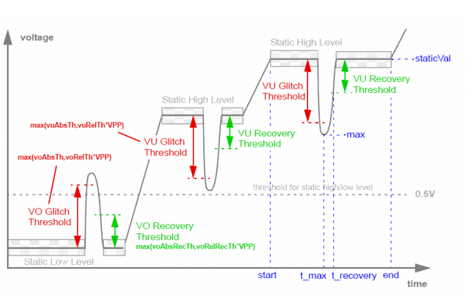
Node glitch analysis is performed as follows:
|
|
avg: Specifies the average glitch voltage level, that is, the average of maximum value of all glitches within one static level. |
|
|
max: Specifies the maximum glitch voltage level, that is, the voltage level of the maximum glitch within the static level. |
|
|
t_max: Specifies the time of the maximum glitch. |
|
|
t_recovery: Specifies the time taken by the signal to recover from the glitch. |
|
|
staticVal: Specifies the static voltage level. |
|
|
Vpp: Specifies the high-level voltage used to calculate glitch threshold based on relative tolerances. |
|
|
start: Specifies the start time of the static voltage level. |
|
|
end: Specifies the end time of the static voltage level. |
|
Specifies the nodes that need to be checked; accepts wildcards (*). |
|||||||||
|
Specifies the relative tolerance for undershoot glitch detection. Default: 0.1 |
|||||||||
|
Specifies the absolute tolerance for undershoot glitch detection. Default: 0.5V |
|||||||||
|
Specifies the relative tolerance for undershoot glitch recovery. Default: 0.1 |
|||||||||
|
Specifies the absolute tolerance for undershoot glitch recovery. Default: 0.5V |
|||||||||
|
Specifies the relative tolerance for overshoot glitch detection. Default: 0.1 |
|||||||||
|
Specifies the absolute tolerance for overshoot glitch detection. Default: 0.5V |
|||||||||
|
Specifies the relative tolerance for overshoot glitch recovery. Default: 0.1 |
|||||||||
|
Specifies the absolute tolerance for overshoot glitch recovery. Default: 0.5V |
|||||||||
|
Specifies the criteria of sorting, which could be one of the following:
Note: The report does not differentiate between overshoot and undershoot glitches. Therefore, you will see the same sorting results when you use max_vo or max_vu. Similarly, you will see the same sorting results when you use avg_vo or avg_vu. |
|||||||||
|
inc: Sorts in increasing order of the column values. dec: Sorts in decreasing order of the column values. Note: It is recommended that you use the type and sort parameters together. type=max_vo is considered as default while sorting. |
|||||||||
|
Specifies the start time of the check window. Default: 0 |
|||||||||
|
Default: unlimited |
|||||||||
|
Default: 5 |
tells the Virtuoso UltraSim simulator to perform a glitch analysis on the nodes vdd1, vdd2, vss1, vss2, out1, and out2 using the defined threshold values for glitch detection, and recovery. The report is sorted based on the maximum overshoot glitches (in increasing order).
Note: The total (generated and consumed) power at the top level is not reported in the power analysis.
The current and power information is also output to a text file. The file name convention is netlistname.pa and the file contains three sections:
If the circuit is simulated more than once (for example, when using alter or sweep), the file name convention changes to netlistname.runnumber.pa.
Note: The report can be imported into Microsoft® Excel for additional analyses.
|
If not specified, all ports at the specified hierarchical level are automatically reported. Note: When a port is specified, the Virtuoso UltraSim simulator does not report the subcircuit power consumption (that is, the Subckt Power Summary section is omitted from the output file). |
|||||||
|
The hierarchical depth of the subcircuits to be checked (default is 1). |
|||||||
|
Sorts the report by the specified value, in decreasing order. The values include:
If sort=avg in the first usim_pa subcircuit and sort=max in the second usim_pa subcircuit, only sort=avg is used. |
|||||||
|
Limits the number of subcircuits to be reported (default is infinity). |
|||||||
|
Turns specified power value on or off (default is off).
|
|||||||
|
Time window for check. start and stop must be paired. If start and stop are not specified, start defaults to 0s and stop defaults to the end of the simulation. |
|||||||
|
Specifies whether or not to check MOS gates. fast_mode=0: Checks all detected ports (default) fast_mode=1: Skips ports that are MOS gates |
The default length for subcircuit instance names is 20 characters. Use the pa_elemlen option to change the name length. For example, usim_opt pa_elemlen=64 sets the maximum name length to 64 characters.
The report format is determined by the sorting criteria. For example, block x1 has two ports, A and B (in/out in subcircuit definition), and two lower-level blocks x1.x1 and x1.x2 (see Figure 8-1 ).
x1 in1 in2 out sub_x1_x1
x2 in out sub_x1_x2
.subckt sub_x1_x1 in1 in2 out
.ends sub_x1_x1
.subckt sub_x1_x2 in out
x3 in1 in2 out sub_x1_x2_x3
.subckt sub_x1_x2_x3 a b c
.ends sub_x1_x2_x3
.ends sub_x1_x2
Figure 8-1 Power Analysis Report Format Example
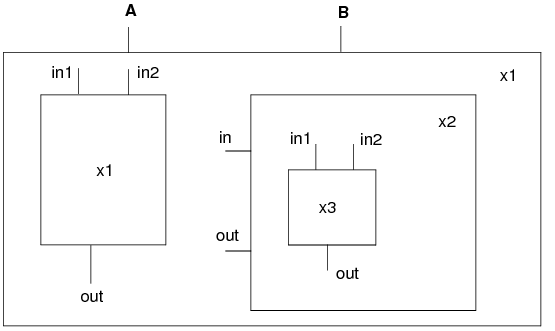
The lower-level blocks and ports are arranged in the following order:
|
|
Block x1.x1 has three ports: in1, in2, and out (in1, in2, and out in subcircuit definition) |
|
|
Block x1.x2 has two ports: xin and xout (in and out in subcircuit definition) |
|
|
Block x1.x2 contains block x1.x2.x3 |
|
|
Block x1.x2.x3 has three ports: in1, in2, and out (a, b, and c in subcircuit definition) |
Note: See Figure 8-1 for the circuit hierarchical structure used in this example.
usim_pa example2 subckt inst=[x1] depth=3 sort=max power=off time_window=[10n 50n]
.usim_pa example2 subckt inst=[x1] depth=3 sort=max power=off time_window=[10n 50n]
The first section of the output file includes the following information:
*** Port Current Summary *******************
Note: See Figure 8-1 for the circuit hierarchical structure used in this example.
usim_pa example3 subckt inst=[x1] depth=3 sort=max power=on time_window=[10n 50n]
The first section of the output file netlistname.pa is the same as in Example 2. The second and third sections of the file include the following information:
*** Port Power Summary **********
*** Subckt Power Summary ******
Note: See Figure 8-1 for the circuit hierarchical structure used in this example.
usim_pa example4 subckt inst=[x1.x2] port=[in] depth=1 sort=max power=on
time_window=[10n 50n]
Since the port is specified, the Virtuoso UltraSim simulator does not report the power consumption for the subcircuit (output file only has two sections: Port Current Summary and Port Power Summary).
*** Port Current Summary *******************
Note: See Figure 8-1 for the circuit hierarchical structure used in this example.
usim_pa example5 subckt inst=[x*] port=[in*] depth=3 sort=avg power=off
time_window=[1n 2n]
tells the Virtuoso UltraSim simulator to print out the current consumption for all ports that have names starting with in and for all subcircuits that have names starting with x. The hierarchical depth is limited to 3, the report is sorted by the avg value, and the time window is from 1 ns to 2 ns.
Note: See Figure 8-1 for the circuit hierarchical structure used in this example.
usim_pa example6 subckt depth=3 sort=max power=on time_window=[100p 2n]
The usim_pa currents command is used to analyze the capacitive, and static and dynamic wasted currents for specified circuits. The analysis results report the RMS and average values of currents consumed by the subcircuit, and its child subcircuits within the specified hierarchical level. The current information is output to a netlistname.pa text file.
|
Note: Wildcards (*) are supported. |
|
|
Static and dynamic wasted current is reported if static=on (default is static=off and only the total wasted current is reported). |
|
In the following Spectre syntax example
usim_pa example1 currents inst=x1 static=on start=100n stop=1000n
the Virtuoso UltraSim simulator reports the capacitive current, as well as the static and dynamic wasted currents for instance x1 over the simulation window of time=100 ns to time=1000 ns.
The following report is generated:
.TITLE 'This file is :./mult16_vec.pa'
*** Subckt Current Summary ***
In the following SPICE syntax example
.usim_pa example2 currents static=on
Based on the specified element list, current threshold, over current duration time, and checking time windows, the Virtuoso UltraSim simulator reports in a netlistName.pcheck file which elements over a specific time window have current over the threshold for a time period equal to or greater than the specified duration. If no time window is specified, the entire simulation period is used.
|
|

|
To limit the number of error messages that will be printed in the Over Current (Excessive Current) Check report, use the pcheck_limit option. |
|
Defines the checking window. Default is the entire simulation time period. |
|||||
|
Defines whether all devices are preserved.
|
pcheck check1 exi elem=[XIO.M12 XIO.M32] ith=5e-3 tth=10n
pcheck check2 exi elem=[X1.X132.*] ith=1e-4 tth=10n time_window=[0 1u 3u 10u]
pcheck check3 exi elem=[*] ith=2e-3 tth=100n
.pcheck check1 exi elem=[XIO.M12 XIO.M32] ith=5e-3 tth=10n
.pcheck check2 exi elem=[X1.X132.*] ith=1e-4 tth=10n time_window=[0 1u 3u 10u]
.pcheck check3 exi elem=[*] ith=2e-3 tth=100n
Note: The element instance list can only contain element names or be enclosed by I( ), single quotation marks ` ', or double quotation marks " " [if only a wildcard * is used, it requires I( ) or quotation marks]. For more information about wildcards, see "Wildcard Rules".
Based on the specified node list, voltage thresholds, over voltage duration time, and checking windows, the Virtuoso UltraSim simulator reports in a netlistName.pcheck file which nodes over a specific time window have voltage over, below, or within the threshold(s) for a time period equal to or greater than the specified duration. If no time window is specified, the entire simulation period is used.
|
|
|
To limit the number of error messages that will be printed in the Over Voltage (Excessive Node Voltage) Check report, use the pcheck_limit option. |
|
vmin=value |
Defines minimum voltage level. If not defined, vmin checking is not performed by simulator. |
||||
|
vmax=value |
Defines maximum voltage level. If not defined, vmax checking is not performed by simulator. |
||||
|
tth=time_duration |
|||||
|
Defines the checking window. Default is the entire simulation time period. |
|||||
|
Defines whether all devices are preserved.
|
|||||
|
option=0|1 |
Defines which voltage threshold is used to report the nodes.
|
pcheck exv1 exv node=[*] vmax=0.8 tth=1n
pcheck exv2 exv node=[*] vmin=0
pcheck exv3 exv node=[*] vmin=0 vmax=0.8 option=0 tth=1n
pcheck exv4 exv node=[*] vmin=0.35 vmax=0.75 option=1 tth=1n
pcheck exv5 exv node=[*] vmin=0.35 vmax=0.75 option=1 tth=1n preserve=all
.pcheck exv1 exv node=[*] vmax=0.8 tth=1n
.pcheck exv2 exv node=[*] vmin=0
.pcheck exv3 exv node=[*] vmin=0 vmax=0.8 option=0 tth=1n
.pcheck exv4 exv node=[*] vmin=0.35 vmax=0.75 option=1 tth=1n
.pcheck exv5 exv node=[*] vmin=0.35 vmax=0.75 option=1 tth=1n preserve=all
The Virtuoso UltraSim simulator reports the DC conducting paths between specified voltage source nodes. All reported DC conducting paths are written into a file with a .pcheck extension. To qualify as a conducting path, each segment in the path must, at a minimum, carry the threshold current specified by the parameter ith.
|
|
|
To limit the number of error messages that will be printed in the DC Path Leakage Current Check report, use the pcheck_limit option. |
|
Specifies that the DC current path is checked for every period, starting from the beginning of each time frame as defined by start and stop. |
|
|
Specifies that the DC current path is checked at each time defined by t+delay_time. t designates the time an input stimulus change occurs. If both period and delay are not specified, the DC path is checked in the time frame defined by start and stop. Note: period and delay cannot be used simultaneously. |
|
|
Specifies that the DC current path is checked at the time defined by at=time1. |
|
|
Specifies time frame for checking (default is full transient simulation). |
|
|
By default, (btwvnode=1) only leakage checks between the nodes driven by voltage sources are performed. With btwvnode=0, the leakage check can be performed between non-vsrc nodes, if they are specified in the node statement. |
|
|
file=filename |
Specifies the user-defined output file. If the file argument is not specified, the DC conducting paths are reported in the netlistname.pcheck file. |
In the following Spectre example
pcheck dc1 dcpath ith=1e-6 tth=10n node=[vdd gnd] delay=5n time_window=[10n 210n]
tells the Virtuoso UltraSim simulator to check the DC current path between vdd and gnd after any input stimulus change, with a delay of 5 ns. The DC current path is checked during the 10 ns and 210 ns time frame. The DC current path is reported in the netlist.pcheck file if the DC current path exceeds 1 uA and lasts longer than 10 ns.
In the following SPICE example
.pcheck dc2 dcpath ith=1e-6 node=[vddh vddl] period=10n time_window=[10n 210n]
tells the simulator to check the DC current path between vddh and vddl every 10 ns, starting at 10 ns and stopping at 210 ns. The DC current path is reported if the DC current path exceeds 1 uA.
In the following Spectre example
pcheck dc3 dcpath node=[vcc vss] at=[130n 150n]
tells the simulator to check the DC current path between vcc and vss at 130 ns and 150 ns. The DC current path is reported if the DC current path exceeds the default value of 50 uA when checked.
pcheck dc4 dcpath inst=[IDIGITAL] xinst=[IDIGIAL.IOSC] ith=10u tth=10n
tells the simulator to check the DC current path between any two voltage sources over the entire simulation time. The DC current path is reported if the DC current path exceeds 10 uA and last longer than 10 ns. Only the IDIGIAL block is checked (the IOSC block inside IDIGIAL is excluded).
Based on the specified node name list, high-z duration time, and checking windows, the Virtuoso UltraSim simulator reports in a netlistName.pcheck file which nodes over the time windows were in high-z state for a time period equal to or greater than the specified duration. If no window is specified, the whole simulation period is used.
Note: See the Notes section for the definition of lth.
Note: See the Notes section for the definition of Rth.
There is an alternative rule for defining a MOSFET to be not conducting. The simulator option mos_on_method defines which rule is used, as shown below.
|
MOSFET is not conducting when Vgs<Vth |
|
|
MOSFET is not conducting when Ids<pck_mos_ids and gds<pck_mos_gds |
You can specify the ids and gds thresholds using the following options:
.usim_opt pck_mos_ids=value //default value is 100nA
.usim_opt pck_mos_gds=value //default value is 1e-5
|
|
|
To limit the number of error messages that will be printed in the High Impedance Node Check report, use the pcheck_limit option. |
|
fanout=0|1|2 |
Optional connection option. If fanout=0, all listed nodes are checked. If fanout=1, only those nodes connected to the metal oxide semiconductor field-effect transistor (MOSFET) gate are checked. If fanout=2, only those nodes connected to the bulk or body of the MOSFET are checked (default is 0). |
|
Defines subcircuit that are excluded from the check when `*' is used in the node name list (wildcard * is supported). |
|
|
Defines the subcircuits that should be included in the check. |
|
|
Defines the time period for checking. The default is the entire transient period. |
|
|
file=filename |
Specifies the user-defined output file. If the file argument is not specified, the design checks are reported in the netlistname.pcheck file. |
pcheck z_check1 zstate node=[xram.*] fanout=1 ztime=50n
pcheck z_check2 zstate node=[*] ztime=1.0e-8 time_window=[1u 9u]
xsubckt=[inv1* ?and]
.pcheck z_check1 zstate node=[xram.*] fanout=1 ztime=50n
.pcheck z_check2 zstate node=[*] ztime=1.0e-8 time_window=[1u 9u]
xsubckt=[inv1* ?and]
|
|
The node instance list can only contain node names and must be enclosed by v( ), single quotation marks ` ', or double quotation marks " " [if only a wildcard * is used, it requires v( ) or quotation marks]. For more information about wildcards, see "Wildcard Rules". |
|
|
When a wildcard is used, the expanded node instance list does not include nodes located within RC networks. You should always review the Virtuoso UltraSim simulator log file for all reported floating nodes (use the warning_limit_float option to print floating nodes). |
.usim_opt res_open = value
The default value of Rth is 100 Mohm.
The Virtuoso UltraSim simulator reports the average charging and discharging current statistics for specified nodes during a checking window (the statistics are output to a netlistName.hotspot report). If a checking window is not specified, the entire simulation period is used.
|
Defines the hot spot factor (0 <= ratio <= 1; default is 0.5). |
|
|
fanout=0|1|2 |
Optional connection option. If fanout=0, all listed nodes are checked. If fanout=1, only those nodes connected to the metal oxide semiconductor field-effect transistor (MOSFET) gate are checked. If fanout=2, only those nodes connected to the bulk or body of the MOSFET are checked (default is 0). |
|
Defines subcircuit that are excluded from the check when `*' is used in the node name list. |
|
|
Checks hot spot for I/O ports of specified subcircuit. Only applied when `*' is specified. |
|
|
Defines the time period for checking. The default is the entire simulation period. |
In the following Spectre example
pcheck hot_chk1 hotspot node=[xtop.x1.*]
tells the Virtuoso UltraSim simulator to report the average current statistics for all nodes in the xtop.x1 block.
In the following SPICE example
.pcheck hot_chk2 hotspot node=[*] ratio=0.8 time_window=[1u 9u]
|
|
The node instance list can only contain node names and must be enclosed by either v(), single quotation marks (`'), or double quotation marks (""). If only a wildcard (*) is used, the node names need to use v() or quotation marks. For more information about wildcards, see "Wildcard Rules". |
|
|
Icin is the average charging current flowing into the capacitances connected to the node |
|
|
Icout is the average discharging current flowing out of the capacitances connected to the node |
|
|
The checking window duration is listed in the from(ns) and to(ns) columns |
The node with the largest current is vpp, which has a sum of charging and discharging average current of 3194.2 uA. Multiplied by the ratio 0.5, the sum of charging and discharging average current is 1597.1 uA. Based on this ratio, all nodes with a current sum larger than 1597.1 uA are included in the report.
Note: If the hot spot factor ratio is changed to 0.6, the x5.nc and x3.n1n646 are excluded from the report.
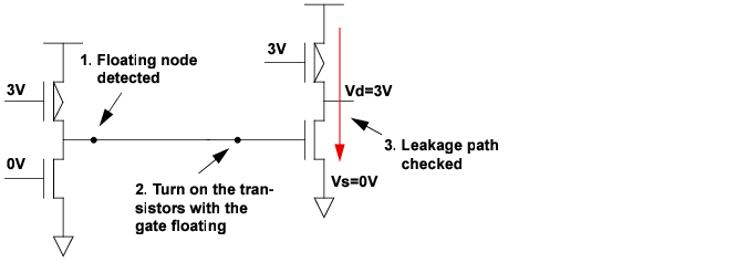
The Virtuoso UltraSim simulator detects Hi-Z nodes and forces their associated fanout transistors to be turned on. If the operation forms any conducting paths between voltage source nodes through the transistor with leakage current larger than the threshold value, then these paths are reported in a netlistName.pcheck file. To qualify as a conducting path, each segment in the path must carry the threshold current specified by the ith parameter.
Note: The definitions of Hi-Z nodes are described in the High Impedance Node Check section.
A voltage source node is a node which is directly connected to a voltage source (includes DC, PWL, and PULSE voltage sources). The ground node is also a voltage source node. Nodes which are shorted to power supply or ground nodes via a 0V DC voltage source, or a PWL source with min=max=0V value may also be specified as nodes in the floatdcpath statement.
Figure 8-2 Floating Gate Induced Leakage Current Check Overview
|
|
|
To limit the number of error messages that will be printed in the Floating Gate Induced Leakage Current Check report, use the pcheck_limit option. |
|
List of voltage source nodes to be checked. Wildcards are supported. |
|
|
Check is performed at every time period, starting at the beginning of time_window (default value is 10 ns or 1% of transient time, whichever time value is longer). Minimum period allowed is 1 ns. |
|
|
Specifies time point for checking (ignored if time_window is specified). |
|
|
By default (btwvnode=1), only leakage checks between the nodes driven by voltage sources are performed. With btwvnode=0, the leakage check can be performed between non-vsrc nodes, if they are specified in the node statement. |
|
|
file=filename |
Specifies the user-defined output file. If the file argument is not specified, the leakage path checks are reported in the netlistname.pcheck file. |
.pcheck dc2 floatdcpath node=[vcc vss] ith=50u at=[130n 150n]
tells the Virtuoso UltraSim simulator to check the DC current path between vcc and vss at 130 ns and 150 ns. The DC current path is reported if the path exceeds 50 uA during the check.
.pcheck dc1 floatdcpath time_window=[200n 600n 1200n 1600n] period=[100n]
The Virtuoso UltraSim simulator reports in a netlistName.pcheck file the nodes that have excessive rise or fall time over a specific time period based on the specified list of nodes, logic voltage thresholds, and checking time windows.
If no checking time windows are specified, the entire simulation period is used.
|
|
|
To limit the number of error messages that will be printed in the Excessive Rise and Fall Time Check report, use the pcheck_limit option. |
|
Note: When multiple xsubckt arguments are specified, only the last one is honored. As a result, the subcircuit name specified with the last xsubckt argument is excluded from the EXRF check. |
|
|
Optional connection option. If fanout=0, all listed nodes are checked. If fanout=1, only those nodes connected to the metal oxide semiconductor field-effect transistor (MOSFET) gate are checked. If fanout=2, only those nodes connected to the bulk or body of the MOSFET are checked (default is 0). |
|
|
Transition time from logic low voltage to logic high voltage. The default value is 5 ns. |
|
|
Transition time from logic high voltage to logic low voltage. The default value is 5 ns. |
|
|
Defines the time period for checking. The default is the entire transient period. |
.pcheck exrf node = [ x1.x2.*] fanout=1 rise=6n fall=4n vlth=0.4 vhth=2.6
This command checks if the signal voltage values at the nodes x1.x2.* have excessive rise and fall times between 100 ns and 2000 ns. A violation is reported in the .pcheck file if the signal rise time exceeds 6 ns, or the signal fall time exceeds 4 ns, or the U-state time exceeds the default value of 5 ns.
The Virtuoso UltraSim simulator allows you to perform timing analysis on specific nodes through a set of commands starting with usim_ta. These commands should be directly embedded in the netlist file, or in a separate file that is included in the netlist file using the include command. The timing check errors are reported in the .ta file. If the netlist file is circuit.sp, then the .ta file is named circuit.ta.
Timing check statements can be embedded within a subcircuit definition. In this case, they apply only to the nodes local to the host circuit, and their check titles are appended by the circuit calls from the top level in the circuit hierarchy. Timing check statements also support the parameters depth = value and subckt = name simulation output statements (see "Supported SPICE Format Simulation Output Statements" for more information). Nodes analyzed with usim_ta are automatically saved as waveforms.
usim_ta ta_all setup node=n1 edge=rise ref_node=clk ref_edge=rise setup_time=2n
subckt=INV depth=2
.usim_ta ta_all setup node=n1 edge=rise ref_node=clk ref_edge=rise setup_time=2n
subckt=INV depth=2
tells the Virtuoso UltraSim simulator to report the setup timing errors for all nodes that match n* in the subcircuit INV and one level below in the circuit hierarchy. See the following sections for timing check statements descriptions.
The timing analysis checks supported by the Virtuoso UltraSim simulator include:
This command is used to report hold timing errors on the specified nodes with respect to a reference node. A hold timing error occurs when a permissible signal transition occurs between the times t_ref and t_ref+hold_time (if hold_time>0), or between t_ref+hold_time and t_ref+window_size (if hold_time<0). Here, t_ref is the time point when a permissible reference transition occurs.
|
Specifies the node on which the hold timing check is performed. Wildcards are supported in the node name (see Chapter 3, "Simulation Options"). |
|
|
edge=rise|fall|both |
The permissible transition type for the signal node. rise, a low-to-high transition is the permissible transition. fall, a high-to-low transition is the permissible transition. both, a low-to-high or a high-to-low transition is a permissible transition. |
|
The name of the reference node. Only a single node is allowed. Wild cards are not supported. |
|
|
Instructs how node and ref_node should be specified. hier (default) - node and ref_node should be full hierarchical names, or equivalent wild card expressions. For ref_scope=hier, node and ref_node can be in different subcircuits. local - node and ref_node should be local names (that is, with no hierarchy delimiter .). If ref_scope=local, node and ref_node in the same subcircuit will be checked. |
|
|
ref_edge=rise|fall|both |
The permissible transition for the reference node. rise, a low-to-high transition is the permissible transition. fall, a high-to-low transition is the permissible transition. both, a low-to-high or a high-to-low transition is a permissible transition. |
|
The hold time. It can be positive or negative. If negative, the window parameter must be specified. |
|
|
window=window_size |
|
|
vl=logic_0_threshold |
The threshold of logic 0 state for a signal. If the signal has a value less than vl, it is considered to be logic 0. |
|
vh=logic_1_threshold |
The threshold of logic 1 state for a signal. If the signal has a value greater than vh, it is considered to be logic 1. |
|
vrl=logic_0_threshold |
The threshold of logic 0 state for a reference. If the reference has a value less than vrl, it is considered to be logic 0. |
|
vrh=logic_01threshold |
The threshold of logic 1 state for a reference. If the reference has a value greater than vrh, it is considered to be logic 1. |
|
depth=value |
|
|
inst=name |
The hold timing check is applied to the subcircuit instances listed (wildcards are supported). |
|
subckt=name |
|
|
xsubckt=name |
|
|
xinst=name |
The hold timing check is excluded from the subcircuit instances listed (wildcards are supported). |
|
Timing analysis start time. The Virtuoso UltraSim simulator does not perform a timing analysis for simulation time < time1. |
|
|
Timing analysis end time. The simulator does not perform a timing analysis for simulation time > time2. |
|
In the following Spectre example
usim_ta ta_all hold node=n1 edge=rise ref_node=clk ref_edge=fall
hold_time=2n
tells the Virtuoso UltraSim simulator to report hold timing errors if the rise transitions on node n1 occur within the 2 ns, after a fall transition on the node clk.
In the following SPICE example
.usim_ta ta_all hold node=n2 edge=both ref_node=clk ref_edge=fall
hold_time=-1n window=5n
tells the simulator to report hold timing errors if the rise or fall transitions on node n2 occur within the time interval of 1 ns before the fall transition of the node clk, and 5 ns after the clk fall transition.
In the following Spectre examples
usim_ta ta_all hold node=x1.x2.sig … ref_node=clk [ref_scope=hier]
usim_ta ta_all hold node=*.sig … ref_node=clk inst=[x1.x2] [ref_scope=hier]
the node x1.x2.sig will be checked against the signal clk, which is taken as the top-level signal.
In the following Spectre example
.usim_ta ta_all hold node=sig … ref_node=clk … subckt=DTrigger ref_scope=local
assuming that there are two subcircuit instances x1 and x2 of type DTrigger, x1.sig will be checked against x1.clk and x2.sig will be checked against x2.clk. x1.sig and x2.clk will not be paired together. Here, clk is the same subcircuit of sig, but it is not considered as the top-level node.
This command is used to report pulse width errors on the waveforms of the specified nodes. Pulse width is defined to be the time interval during which the signal in a node stays in the low or high state. A pulse width error occurs when the pulse width of a signal falls outside the range (min_low_time, max_low_time) for the logic 0 state, or the range (min_high_time, max_high_time) for the logic 1 state.
If the logic 0 state and logic 1 state thresholds for the signal are not specified on the command card, the default values are used. The default values can be set using the command usim_opt vl = value vh = value.
|
Specifies the name of the node on which the hold timing check is performed. Wildcards are supported in the node name (see Chapter 3, "Simulation Options"). |
|
|
vl=logic_0_threshold |
The threshold of the logic 0 state for the signal. If the signal has value less than vl, it is considered to be logic 0. |
|
vh=logic_1_threshold |
The threshold of the logic 1 state for the signal. If the signal has value greater than vh, it is considered to be logic 1. |
|
depth=value |
|
|
inst=name |
The pulse width check is applied to the subcircuit instances listed (wildcards are supported). |
|
subckt=name |
|
|
xsubckt=name |
|
|
xinst=name |
The pulse width check is excluded from the subcircuit instances listed (wildcards are supported). |
|
Timing analysis start time. The Virtuoso UltraSim simulator does not perform a timing analysis for simulation time < time1. |
|
|
Timing analysis end time. The simulator does not perform a timing analysis for simulation time > time2. |
|
usim_ta ta_all pulsew node=n1 tmin_low=4n tmax_low=6n tmin_high=5n
tmax_high=8n
.usim_ta ta_all pulsew node=n1 tmin_low=4n tmax_low=6n tmin_high=5n
tmax_high=8n
tells the Virtuoso UltraSim simulator to report pulse width errors if node n1 stays in the logic 0 state for less than 4 ns or longer than 6 ns, or if it stays in the logic 1 state for less than 5 ns or more than 8 ns.
This command is used to report setup timing errors on the specified node(s) with respect to a reference node. A setup timing error has occurred if a permissible signal transition occurs between the times t_ref-setup_time and t_ref+window_size, where t_ref is the time when a permissible reference transition occurs.
|
Specifies the name of the node on which the setup timing check is performed. Wildcards are supported in the node name (see Chapter 3, "Simulation Options"). |
|
|
edge=(rise|fall|both) |
The permissible transition type for the signal node. rise, a low-to-high transition is the permissible transition. fall, a high-to-low transition is the permissible transition. both, a low-to-high or a high-to-low transition is a permissible transition. |
|
The name of the reference node. Only a single node is allowed. |
|
|
Instructs how node and ref_node should be specified. hier (default) - node and ref_node should be full hierarchical names, or equivalent wild card expressions. For ref_scope=hier, node and ref_node can be in different subcircuits. local - node and ref_node should be local names (that is, with no hierarchy delimiter .). If ref_scope=local, node and ref_node in the same subcircuit will be checked. |
|
|
ref_edge=(rise|fall|both) |
The permissible transition for the reference node. rise, a low-to-high transition is the permissible transition. fall, a high-to-low transition is the permissible transition. both, a low-to-high or a high-to-low transition is a permissible transition. |
|
The setup time. It can be positive or negative. If negative, the window parameter must be specified. |
|
|
window=window_size |
|
|
vl=logic_0_threshold |
The threshold of logic 0 state for a signal. If the signal has a value less than vl, it is considered to be logic 0. |
|
vh=logic_1_threshold |
The threshold of logic 1state for a signal. If the signal has a value greater than vh, it is considered to be logic 1. |
|
vrl=logic_0_threshold |
The threshold of logic 0 state for a reference. If the reference has a value less than vrl, it is considered to be logic 0. |
|
vrh=logic_1_threshold |
The threshold of logic 1 state for a reference. If the reference has a value greater than vrh, it is considered to be logic 1. |
|
depth=value |
|
|
inst=name |
The setup timing check is applied to the subcircuit instances listed (wildcards are supported). |
|
subckt=name |
|
|
xsubckt=name |
|
|
xinst=name |
The setup timing check is excluded from the subcircuit instances listed (wildcards are supported). |
|
Timing analysis start time. The Virtuoso UltraSim simulator does not perform a timing analysis for simulation time < time1. |
|
|
Timing analysis end time. The simulator does not perform a timing analysis for simulation time > time2. |
|
In the following Spectre example
usim_ta ta_all setup node=n1 edge=rise ref_node=clk ref_edge=rise
setup_time=2n
tells the Virtuoso UltraSim simulator to report setup timing errors if the rise transitions on node n1 occur within the 2 ns before a rise transition on the node clk. Since the low and high thresholds are not specified in the command, the values in usim_opt are used in the analysis.
In the following SPICE example
.usim_ta ta_all setup node=n2 edge=both ref_node=clk ref_edge=fall
setup_time=-1ns window=3ns
tells the simulator to report setup timing errors if the rise or the fall transitions on node n2 occur within the time interval of 1 ns after the fall transition of the node clk, and 3 ns after the clk fall transition.
This command is used to report timing edge errors on the specified node(s) with respect to a reference node. A timing edge error occurs when the permissible signal transition time falls outside the range t_ref+min_time and t_ref+max_time, where t_ref is the time that the permissible reference transition occurs.
A permissible transition occurs when the waveform crosses the corresponding logic threshold. For example, when a waveform crosses the logic 1 threshold while rising, it has a RISE transition. If the logic 0 state and logic 1 state thresholds for the signal, reference, or both, are not specified on the command card, the default values are used. The default values can be set using the command usim_opt vl = value vh = value. The trigger option allows you to decide whether a permissible signal transition, a permissible reference transition, or both trigger the timing edge check.
|
Specifies the name of the node on which the timing edge check is performed. Wildcards are supported in the node name (see Chapter 3, "Simulation Options"). |
|
|
edge=(rise|fall|both) |
The permissible transition type for the signal nodes. rise, a low-to-high transition is the permissible transition. fall, a high-to-low transition is the permissible transition. both, a low-to-high or a high-to-low transition is a permissible transition. |
|
The name of the reference node. Only a single node is allowed. |
|
|
Instructs how node and ref_node should be specified. hier (default) - node and ref_node should be full hierarchical names, or equivalent wild card expressions. For ref_scope=hier, node and ref_node can be in different subcircuits. local - node and ref_node should be local names (that is, with no hierarchy delimiter .). If ref_scope=local, node and ref_node in the same subcircuit will be checked. |
|
|
ref_edge=(rise|fall|both) |
The permissible transition type for the reference nodes. rise, a low-to-high transition is the permissible transition. fall, a high-to-low transition is the permissible transition. both, a low-to-high or a high-to-low transition is a permissible transition. |
|
The minimum value of the delay between the permissible transitions of the signal and the reference. |
|
|
The maximum value of the delay between the permissible transitions of the signal and the reference. |
|
|
vl=logic_0_threshold |
The threshold of logic 0 state for a signal. If the signal has a value less than vl, it is considered to be logic 0. |
|
vh=logic_1_threshold |
The threshold of logic 1 state for a signal. If the signal has a value greater than vh, it is considered to be logic 1. |
|
vrl=logic_0_threshold |
The threshold of logic 0 state for a reference. If the reference has a value less than vrl, it is considered to be logic 0. |
|
vrh=logic_1_threshold |
The threshold of logic 1 state for a reference. If the reference has a value greater than vrh, it is considered to be logic 1. |
|
trigger=(ref|sig|both) |
The trigger to start a timing edge check. ref, a permissible transition at a reference triggers the check (this is the default value) sig, a permissible transition at a signal triggers the check. both, a permissible transition if a reference or a signal triggers the check. |
|
depth=value |
|
|
inst=name |
The timing edge check is applied to the subcircuit instances listed (wildcards are supported). |
|
subckt=name |
|
|
xsubckt=name |
|
|
xinst=name |
The timing edge check is excluded from the subcircuit instances listed (wildcards are supported). |
|
Timing analysis start time. The Virtuoso UltraSim simulator does not perform a timing analysis for simulation time < time1. |
|
|
Timing analysis end time. The simulator does not perform a timing analysis for simulation time > time2. |
|
In the following Spectre example
usim_ta ta_all edge node=n1 edge=rise ref_node=clk ref_edge=rise
td_min=2n td_max=5n
tells the Virtuoso UltraSim simulator to report timing edge errors if the delay between the rise transitions at node n1 and reference clk is less than 2 ns, or longer than 5 ns. Since the default value of trigger is ref, only a rise transition of the reference can trigger a timing edge check.
In the following SPICE example
.usim_ta ta_all edge node=n2 edge=rise ref_node=clk ref_edge=rise
td_min=2n td_max=5n trigger=sig
tells the simulator to report timing edge errors if the delay is outside the range of 2 ns and 5 ns. In this case, only a rise transition of the signal at n2 can trigger a timing edge check.
|
|
Transient simulation with the specified parameter set at the lower and upper limits, respectively. |
The measurement results for the lower and upper limits need to meet the pre-determined goal with one limit, and fail with the other limit (otherwise the simulator ends the simulation and prints a message).
The search range can be split into halves by choosing a new search range. The measurement results determine whether the first or second half is used in the search range.
To use the simulator for bisection timing optimization, more accurate settings than the default simulator settings may be required. Cadence recommends first evaluating which Virtuoso UltraSim sim_mode and speed fulfils the specific accuracy requirements of your design before using bisection timing optimization (see Chapter 3, "Simulation Options" for more information about sim_mode and speed).
The Virtuoso UltraSim simulator reports the search process and optimized parameters in the netlistName.optlog file, and also generates waveforms and the measurement result (netlistName.mt0) for the final simulation.
The following statements can be used for model optimization (.model), parameter optimization (.param), measurement (.measure), and transient analysis (.tran).
|
Specifies the relative tolerance of the input parameter (default value is 0.001) |
|
|
Specifies the relative tolerance of the output variable (default value is 0.001) |
|
|
Specifies the maximum number of iterations (default value is 20 iterations) |
|
Name of the parameter function. Must be in the form of optxxxx. |
|
|
Specifies the measurement functions supported in a base-level .measure statement |
|
This statement defines the bisection and optimization methods.
|
Name of the parameter function given in the .param statement. |
|
|
Name of the .measure statement. |
|
|
Name of the optimization model given in the .model statement. |
|
|
off - netlist file is parsed and simulation database is rebuilt for each bisection iteration (default). on - netlist file parsing and building of simulation database is skipped for all bisection iterations after the first iteration (simulation database from first iteration is reused). This feature provides a performance advantage, but is limited to bisection applications with no change in the topology and initial circuit conditions between iterations. |
The following example illustrates how to measure the setup time of a delay-type flip flop (D-FF).
Figure 8-3 D-FF Setup Time Optimization
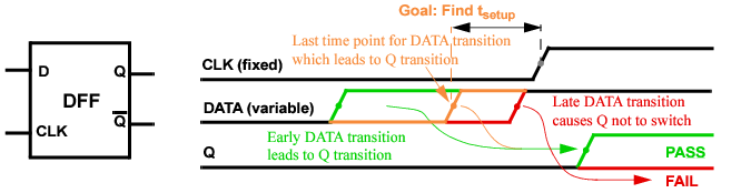
The D-FF has two input signals (DATA and CLK) and two output signals (Q and Q_). The assumption is that both input signals switch (0->1) at Td and Tclk, respectively. It is expected that the data will remain stable during setup time, until CLK switches.
The transition needs to satisfy the following condition,
In this case, a transition (0->1) at the output of the D-FF Q occurs. Otherwise, no transition is found by the simulator and output Q remains at 0. The transition at the output can be detected by measuring the max value at Q. If the measurement result is 1, there is a transition; if 0, no transition occurs.
The following is a sample top-level netlist file containing bisection timing optimization settings.
**** Search setup time for D-FF by bisection method ****
// PWL stimulus for CLK & data
// td=delay characterizes the setup time and is to be adjusted by bisection
Vclk CLK 0 pwl(0n 0 1n 0 1.5n vdd 3n vdd 3.5n 0 10n 0 10.5n vdd)
Vdata data 0 pwl(0n 0 5n 0 5.5n vdd td=delay)
// set delay to be the input variable, and its searching range
// set optimization method to be bisection
.model optmod opt method=bisection
// set measurement to find the transition of output and its goal value
.measure tran vout max v(Q) goal='0.9*vdd'
// set bisection transient simulation
.tran 0.1n 20n sweep optimize=opt1 results=vout model=optmod
.measure tran setup_time trig v(data) value='0.5*vdd' rise=1 td=5n
+ targ v(clk) value='0.5*vdd' rise=1 td=5n
The following sample output file shows the simulation results. The optimized value of delay is 5.083 ns. With this delay, the voltage at the Q output of the DFF is 2.504 v.
|
|
Netlist File Parameter Check checks whether the element size and simulation temperature are in the reasonable range or not. |
|
|
Print Parameters in Subcircuit prints the parameters located in a subcircuit. |
|
|
Resistor and Capacitor Statistical Checks determines whether resistor or capacitor values are within a specified range. |
|
|
Substrate Forward-Bias Check checks whether a MOSFET substrate becomes forward-biased. |
|
|
Static MOS Voltage Check monitors whether MOSFET bias voltage exceeds specified bounds or conditions. |
|
|
Static Diode Voltage Check checks the diode bias voltage after the netlist file is parsed and generates a report indicating whether the voltages exceeded the specified upper and lower bounds, or met the specified conditions. |
|
|
Static NMOS and PMOS Bulk Forward-Bias Checks determines whether bulk to drain/source junctions of NMOSFETs or PMOSFETs become forward-biased. |
|
|
Detect Conducting NMOSFETs and PMOSFETs compares the MOSFET gate voltage with the drain/source voltages to detect any transistors that cannot be turned off. |
|
|
Detect NMOS Connected to VDD detects NMOSFETs with terminal(s) that are directly connected to the constant or PWL voltage sources, which have a voltage value higher than vhth (without running transient simulation). |
|
|
Detect PMOS Connected to GND detects PMOSFETs with terminal(s) that are directly connected to the constant or PWL voltage sources, which have a voltage value lower than vlth (without running transient simulation). |
|
|
Static Maximum Leakage Path Check detects obvious DC leakage paths between all voltage sources through MOSFETs or other elements that are always on. |
|
|
Static High Impedance Check detects high impedance nodes without running DC or transient simulations. |
|
|
Static RC Delay Path Check analyzes the rise or fall time of any MOSFET gate nodes or output nodes without running transient simulation |
|
|
Static ERC Check detects electrical design rule violations without running DC or transient simulations. |
|
|
Static DC Path Check detects a DC path between voltage sources without running DC or transient simulation. |
|
|
info Analysis gives access to input/output values and operating-point parameters. |
|
|
Partition and Node Connectivity Analysis used for debugging (for example, checking the size of partitions and node connectivity). |
|
|
Warning Message Limit Categories customizes how warning messages are handled by the Virtuoso UltraSim simulator. |
The chk_param command checks whether or not the element sizes and simulation temperatures are within a reasonable range. This command is executed after the netlist file is parsed, and the Virtuoso UltraSim simulator generates a report file with a .rpt_chkpar suffix.
When the checked data exceeds specified or default soft upper/lower limits, warning messages are issued. If the data abnormality exceeds specified or default absolute limits, error messages are generated and the simulation stops. Multiple chk_param command lines are supported by the Virtuoso UltraSim simulator.
Note: All errors are collected and printed by chk_param, and then the simulation is stopped (that is, chk_param is always performed on all instance parameters). If optional arguments are specified, the related parameters are checked using the specified value and the remaining parameters are checked using the default values.
|
Note: The value needs to meet the following criteria: ermincap <= wamincap <= wamaxcap <= ermaxcap (otherwise a warning message is issued and the default value is used instead). |
|
|
Note: The value needs to meet the following criteria: erminres <= waminres <= wamaxres <= ermaxres (otherwise a warning message is issued and the default value is used instead). |
|
|
Note: The value needs to meet the following criteria: erminmosw <= waminmosw <= wamaxmosw <= ermaxmosw (otherwise a warning message is issued and the default value is used instead). |
|
|
Note: The value needs to meet the following criteria: erminmosl <= waminmosl <= wamaxmosl <= ermaxmosl (otherwise a warning message is issued and the default value is used instead). |
|
|
Note: The value needs to meet the following criteria: wamaxmosad <= ermaxmosad (otherwise a warning message is issued and the default value is used instead). |
|
|
Note: The value needs to meet the following criteria: wamaxmosas <= ermaxmosas (otherwise a warning message is issued and the default value is used instead). |
|
|
Note: The value needs to meet the following criteria: wamaxmospd <= ermaxmospd (otherwise a warning message is issued and the default value is used instead). |
|
|
Note: The value needs to meet the following criteria: wamaxmosps <= ermaxmosps (otherwise a warning message is issued and the default value is used instead). |
|
|
Note: The ermaxmostox and wamaxmostox arguments should be specified in the same line of .usim_report. |
|
|
Note: The wamaxmostox and ermaxmostox arguments should be specified in the same line of .usim_report. |
|
|
Note: The value needs to meet the following criteria: erminmostox <= waminmostox <= wamaxmostox <= ermaxmostox (otherwise a warning message is issued and the default value is used instead). |
|
|
Note: The value needs to meet the following criteria: ermindiodew <= wamindiodew <= wamaxdiodew <= ermaxdiodew (otherwise a warning message is issued and the default value is used instead). |
|
|
Note: The value needs to meet the following criteria: ermindiodel <= wamindiodel <= wamaxdiodel <= ermaxdiodel (otherwise a warning message is issued and the default value is used instead). |
|
|
Note: The value needs to meet the following criteria: ermindiodea <= wamindiodea <= wamaxdiodea <= ermaxdiodea (otherwise a warning message is issued and the default value is used instead). |
|
|
The simulator issues a warning message and continues the simulation if the circuit temperature, in degrees Celsius, exceeds the specified upper bound value (default value is 150) |
|
|
The simulator issues a warning message and continues the simulation if the circuit temperature, in degrees Celsius, is less than the specified lower bound value (default value is -100) Note: The value needs to meet the following criteria: ermintemp <= wamintemp <= wamaxtemp <= ermaxtemp (otherwise a warning message is issued and the default value is used instead). |
|
|
Default: 1.79769e308 |
|
|
Default: 1.79769e308 |
|
|
Default: -1.79769e308 |
|
|
Note: The value needs to meet the following criteria: erminfactor <= waminfactor <= wamaxfactor <= ermaxfactor (a warning message is issued if the criteria is not met). Default: -1.79769e308 |
|
|
Note: If the model argument is not specified, the check is applied to all instances. |
In the following Spectre example
In the following SPICE example
.usim_report chk_param ermaxmosl=2u wamaxmosl=1u erminmosl=0.09u waminmosl=0.1u
In the following Spectre example
usim_report chk_param ermaxmosl=2u wamaxmosl=1u erminmosl=0.09u waminmosl=0.1u
model=hvmos
The following is an example of a xxxx.rpt_chkpar report file.
****** Parameters Check Errors ******
Model Subckt Parameter Limits Instance
resistor --- r = -0.12 ( < 0.0 ) r23
mos1 por l = 1.0e-9 ( < 1.0e-8 ) xtop.xpor.m100
****** Parameters Check Warnings*******
Total of 2 warning(s) reported.
Model Subckt Parameter Limits Instance
diode1 bg w = 0.002 ( < 0.003 ) x0.x1.x2.x3.d4
capacitor --- c = 1.0e-7 ( > 1.0e-8 ) c1
****** End of Parameter Check. ******
.usim_report param param_name [depth=..]
This option enables you to print subcircuit parameters into a netlist.para_rpt file. The option also supports wildcards and allows use of the depth argument to limit the levels of hierarchy (default for depth is infinity). Matching is case insensitive.
For more information about wildcards, see "Wildcard Rules".
In the following Spectre example
tells the simulator to print out all of the parameters from the entire design hierarchy.
In the following SPICE example
tells the simulator to print out all of the top level parameters.
In the following Spectre example
tells the simulator to look for a parameter named a in instance x1. If no match is found, the simulator issues a warning message.
tells the simulator to print out all of the parameters in instance x1 and all the instances below x1.
usim_report param x1*.* depth=2
Examples of instance names starting with x1 include x1.aa, x1a.b, x1.x2.bb, and x1b.x3.bb (aa, b, and bb are the parameter names).
usim_report resistor type=warning rmax=value
usim_report resistor type=distr rmin=value rmax=value
usim_report resistor type=print rmin=value rmax=value nlimit=num sort=[dec|inc]
.usim_report resistor type=warning rmax=value
.usim_report resistor type=distr rmin=value rmax=value
.usim_report resistor type=print rmin=value rmax=value nlimit=num sort=[dec|inc]
|
|
type=warning prints a warning about small resistors and reports the number of resistors with values below rmax. |
|
|
type=distr prints resistor statistics into a xxxx.chk_resistor log file for resistors with values between rmin and rmax. |
|
|
type=print prints resistors with values between rmin and rmax into a xxxx.chk_resistor log file. |
|
Specifies upper bound of resistor value to be reported (default value is 0.1 ohms). |
|
|
Specifies lower bound of resistor value to be reported (default value is 0). |
|
|
Limits number of resistors printed in report (integer; default value is 10 resistors). |
|
|
Specifies sorting order printed resistors. If set to inc, resistors are sorted in increasing order of their values (default). If set to dec, resistors are sorted in decreasing order of their values. |
In the following Spectre example
usim_report resistor type=warning rmax=0.001
In the following SPICE example
.usim_report resistor type=distr rmin=0 rmax=0.02
The simulator generates statistics for resistors with values between 0 and 0.02 ohms in a xxxx.chk_resistor log file.
In the following Spectre example
usim_report resistor type=print rmin=0 rmax=0.02 nlimit=30 sort=dec
The simulator prints the resistors with values between 0 and 0.02 ohms in a xxxx.chk_resistor log file. The resistors are sorted in decreasing order of their value. A total of 30 resistors are printed because nlimit=30.
The following is a sample xxxx.chk_resistor log file (includes resistor names and values):
.TITLE 'This file is :./test.chk_resistor'
.Usim_report resistor type=distr rmin=0 rmax=0.02
.Usim_report resistor type=print rmin=0 rmax=0.02 nlimit=30 sort=dec
|
|
type=warning prints a warning about small capacitors and reports the number of capacitors with values below cmax. |
|
|
type=distr prints capacitor statistics into a xxxx.chk_capacitor log file for capacitors with values between cmin and cmax. |
|
|
type=print prints capacitors with values between cmin and cmax into a xxxx.chk_capacitor log file. |
|
Specifies upper bound of capacitor value to be reported (default value is 1e-16 F). |
|
|
Specifies lower bound of capacitor value to be reported (default value is 0). |
|
|
Limits number of capacitors printed in report (integer; default value is 10 capacitors). |
|
|
Specifies sorting order for printed capacitors. If set to inc, capacitors are sorted in increasing order of their values (default). If set to dec, capacitors are sorted in decreasing order of their values. |
In the following Spectre example
usim_report capacitor type=warning cmax=1e-17
In the following SPICE example
.usim_report capacitor type=distr cmin=0 cmax=1e-17
The simulator generates statistics for capacitors with values between 0 and 0.01f F in a xxxx.chk_capacitor log file.
In the following Spectre example
usim_report capacitor type=print cmin=0 cmax=1e-17 nlimit=30 sort=dec
The simulator prints the capacitors with values between 0 and 0.01f F in a xxxx.chk_capacitor log file. The capacitors are sorted in decreasing order of their value. A total of 30 capacitors are printed because nlimit=30.
The following is a sample xxxx.chk_capacitor log file (includes capacitor names and values):
.TITLE 'This file is :./pump.chk_capacitor'
.Usim_report capacitor type=print cmin=0 cmax=20p nlimit=10 sort=dec
The chk_substrate command is used to check if a MOSFET substrate becomes forward-biased. The Virtuoso UltraSim simulator generates a report file with a .rpt_chksubs suffix (for example, if the netlist file name is circuit.sp, the report is named circuit.rpt_chksubs).
Note: This command can only be used to check MOSFET substrates, not other PN junctions.
|
Note: The title argument only applies to transient simulations. |
|||||||
|
|||||||
|
Specifies maximum number of warning messages issued (default number is 1000 messages). |
|||||||
|
Specifies threshold voltage (default value is 0.5 v). Note: The vt argument only applies to transient simulations. |
|||||||
|
Specifies threshold current (default value is 0 A). Note: The ith argument only applies to transient simulations. |
|||||||
|
Duration time (default value is 5 ns). Note: The tth argument only applies to transient simulations. |
|||||||
|
Specifies checking start time (default value is 0). Note: The start argument only applies to transient simulations. |
|||||||
|
Specifies checking stop time (default value is transient stop time). Note: The stop argument only applies to transient simulations. |
|||||||
|
Specifies the MOSFET model names to be checked. When the model argument is used, the vt and ith values apply to MOSFETs for the specified model (all MOSFET instances of remaining models are checked using default values). |
In the following Spectre example
usim_report chk_substrate sub1 mode=0
The Virtuoso UltraSim simulator checks the substrates for all the MOSFET models to see if any are forward-biased (checks performed before DC initialization). All warnings issued by the simulator are labelled with sub1 in the .rpt_chksubs file.
In the following SPICE example
.usim_report chk_substrate sub2 mode=2 vt=0.15
The simulator checks the substrates for all the MOSFET models before DC initialization and during the transient simulation. If any MOSFET substrate PN junctions are forward-biased by an amount greater than 0.15 v, warnings labelled with sub2 are issued by the simulator.
In the following Spectre example
usim_report chk_substrate subscheck3 mode=1 vt=0.6
usim_report chk_substrate subscheck4 mode=1 vt=0.5 model=lvmos
The simulator checks the substrates for all the MOSFET models during the transient simulation. If any MOSFET substrate PN junctions are forward-biased by an amount greater than 0.6 v, subscheck3 warnings are issued by the simulator. If the LVMOS model MOSFETs are forward-biased more than 0.5 v, warnings labelled with subscheck4 are issued.
Here is an example of a .rpt_chksubs report file.
****** MOS Substrate Forward Biased Before DC ******
Model Subckt vb Source Instance
nmos1 or 3.0000e+00 vddh xtop.xor.m100
pmos2 or -2.0000e+00 vss xtop.xor.m101
****** MOS Substrate Forward Biased During Simulation *****
Title Model Subckt Time Vb Vs Vd Instance
sub1 n1 por 3.0e-9 1.8000e+00 1.9387e+00 1.9629e+00 xtop.xpor.m100
sub2 p1 amp 3.0e-6 1.8000e+00 1.9997e+00 1.9507e+00 xtop.xamp.m200
|
Specifies the model to be checked. The voltage check is applied to transistors with model card name model_name. |
|
|
Specifies the subcircuits to be checked. The voltage check is applied to transistors belonging to subcircuits. Wildcard (*) characters can be used. |
|
|
Specifies the subcircuits not to be checked (wildcard characters can be used). |
|
|
Specifies the instances not to be checked (wildcard characters can be used). |
|
|
Reports the condition if Vgd is less than the specified lower bound voltage value. |
|
|
Reports the condition if Vgd is greater than the specified upper bound voltage value. |
|
|
Reports the condition if Vgs is less than the specified lower bound voltage value. |
|
|
Reports the condition if Vgs is greater than the specified upper bound voltage value. |
|
|
Reports the condition if Vgb is less than the specified lower bound voltage value. |
|
|
Reports the condition if Vgb is greater than the specified upper bound voltage value. |
|
|
Reports the condition if Vds is less than the specified lower bound voltage value. |
|
|
Reports the condition if Vds is greater than the specified upper bound voltage value. |
|
|
Reports the condition if Vdb is less than the specified lower bound voltage value. |
|
|
Reports the condition if Vdb is greater than the specified upper bound voltage value. |
|
|
Reports the condition if Vsb is less than the specified lower bound voltage value. |
|
|
Reports the condition if Vsb is greater than the specified upper bound voltage value |
|
|
Defines the conditional expression as the checking criteria. When the condition is met, the simulator generates a report. The conditional expression supports the following operators: <, >, <=, >=, ==, ||, &&, and variables: vgs, vgd, vgb, vds, vdb, vsb, vg, vd, vb, vs, l, w. |
|
|
Specifies the conduction mode of MOSFETs. When set to 1 (default), the conduction state of MOSFETs is determined by the gate voltage. When set to 2, the MOSFETs are always in the conductive state disregarding the gate voltage. |
|
|
Specifies whether or not to report the conducting paths. If set to 0 (default) paths are not reported. If set to 1, the conducting paths from the MOSFET terminals to the voltage sources are reported. |
|
|
Specifies whether or not to report the node voltages propagated from voltage sources. If set to 0 (default), the node voltage is not reported. If set to 1, the minimum and maximum values of the node voltages propagated from voltage sources, and the depth of propagation paths, are reported. |
|
|
Specifies whether or not to propagate the node voltages through the capacitor. If set to 0 (default), the node voltages do not propagate through the capacitor. If set to 1, the AC voltage propagates through the capacitor. If set to 2, both DC and AC voltages propagate through the capacitor. |
|
|
When ppos_nneg is set to 1, positive voltage sources can only be propagated through PMOSFETs, and negative or zero voltage sources can only be propagated through NMOSFETs (default value is 0; no limitation on the type of MOSFETs during voltage propagation). |
|
|
When specified, voltage from the voltage source element <elem_name> is propagated with values vmin and vmax. If vhth is set, vmax needs to be greater than or equal to vhth for propagation to begin. If vlth is set, vmin needs to be lower than or equal to vlth for propagation to begin (by default, only voltage from constant voltage sources is propagated). Multiple vsources are supported by the simulator. |
|
|
When specified, voltage from the voltage source node <node_name> is propagated with values vmin and vmax. If vhth is set, vmax needs to be greater than or equal to vhth for propagation to begin. If vlth is set, vmin needs to be lower than or equal to vlth for propagation to begin (by default, only voltage from constant voltage sources is propagated). Multiple vsource nodes are supported by the simulator. |
|
|
When xt_vsrc is set to 1, voltage propagation starts only from highest and lowest constant voltage sources. When xt_vsrc is set to 0, voltage propagation starts from all constant voltage sources. In either case, the selection is subject to the rules set by vhth and vlth (default value is 0). |
In the following Spectre example
and the following SPICE example
The chk_mosv command reports only the maximum and minimum propagated voltages from VPWR to VGND.
In the following Spectre example
usim_report chk_mosv chk1 model=nch inst=[*] xinst=[x1.x2 x1.x3] vgsu=1.5 vdsl=0.1
rpt_path=1
The Virtuoso UltraSim simulator checks if the voltage for all of the nch MOSFETs Vgs and Vds are within the specified bounds. The transistors located in instances x1.x2 and x1.x3 are excluded from the voltage check. The MOSFETs with Vgs>1.5 or Vds<0.1 are reported in the xxxx.rpt_chkmosv log file. With rpt_path=1, the conducting path from the MOSFET terminals to voltage sources is reported.
In the following SPICE example
.usim_report chk_mosv chk2 model=nch inst=[x1.*] skipinst=[x1.x2] vhth=0.9
vgsu=1.5
The simulator checks if the voltage of nch MOSFETs located in instance x1 for Vgs is less than 1.5 v. The voltage propagation only starts from voltage sources with values equal to or greater than 0.9 v. Voltage is not propagated through instance x1.x2. The MOSFETs with Vgs>1.5 are reported.
In the following Spectre example
usim_report chk_mosv chk3 model=nch subckt=[nor2 nand2] maxmos=2 ppos_nneg=1
vgsu=1.5
The simulator checks the voltage of nch MOSFETs belonging to subcircuit nor2 or nand2. The MOSFET is reported if Vgs>1.5.
During voltage propagation, only the nodes that can be connected to a voltage source by going through a maximum of two MOSFETs are considered. With ppos_nneg=1, positive voltage sources can only be propagated through PMOSFETs, and negative or zero voltage sources can only be propagated through NMOSFETs.
In the following SPICE example
.usim_report chk_mosv chk4 model=pch cond='vgs<1 || vds>1.8'
The simulator checks the voltage of all nch MOSFETs. If a nch MOSFET has Vgs<1 or Vds>1.8, then the MOSFET is reported in the xxxx.chk_mosv log file.
The following is an example of a xxxx.chk_mosv log file.
Total of 4 Warnings reported in mosv2.
Total of 2 Warnings reported in chk2.
This command is used to check the diode bias voltage after the netlist file is parsed. In addition, it generates a report indicating whether the voltages exceeded the specified upper and lower bounds, or met the specified conditions. You can use the mode argument to specify the criteria that will be used to estimate the diode bias voltage (vpn):
When mode=0 (default), the following equation is used:
When mode=1, the following equation is used:
The report file name format for this check is xxxx.rpt_chkdiov.
|
Specifies the subcircuits to be checked. Wildcard characters can be used. |
|
|
Specifies the instances to be checked. Wildcard characters can be used. |
|
|
Specifies the subcircuits to be excluded from the check. Wildcard characters can be used. |
|
|
Specifies the instances to be excluded from the check. Wildcard characters can be used. |
|
|
Specifies the subcircuits removed from the netlist. Wildcard characters can be used. |
|
|
Specifies the instances removed from the netlist. Wildcard characters can be used. |
|
|
Starts voltage propagation only from constant voltage sources with value greater than or equal to vhth. |
|
|
Starts voltage propagation only from constant voltage sources with value lower than or equal to vlth. |
|
|
Reports the condition if vpn is less than the specified lower bound voltage value. |
|
|
Reports the condition if vpn is greater than the specified upper bound voltage value. |
|
|
Specifies whether to report only definite violations or all possible violations. When set to 0 (default), only the definite violations will be reported. When set to 1, all possible violations will be reported. |
|
|
Defines the conditional expression as the checking criteria. When the condition is met, the simulator generates a report. The conditional expression supports the following operators: <, >, <=, >=, ==, ||, &&, and variables: vpn, vp, vn, l, w. Note: The conditional check can be combined with the checks based on the lower and upper bounds. |
|
|
Specifies the conduction mode of MOSFETs. When set to 1 (default), the conduction state of MOSFETs is determined by the gate voltage. When set to 2, the MOSFETs are always in the conductive state disregarding the gate voltage. |
|
|
Specifies whether or not to report the node voltages propagated from voltage sources. If set to 0 (default), the node voltage is not reported. If set to 1, the minimum and maximum values of the node voltages propagated from voltage sources, and the depth of propagation paths, are reported. |
|
|
Specifies whether to report the conductive paths from the MOSFET terminals to the voltage sources. When set to 1, the software reports the conductive paths. The default value is 0. |
|
|
When set to 1, propagates positive voltage sources only through PMOSFETs, and negative or zero voltage sources only through NMOSFETs. The default value is 0. |
|
|
Propagates the voltage from the voltage source element elem_name with the vmin and vmax values. If vhth is set, vmax must be greater than or equal to vhth to start propagation. If vlth is set, vmin must be lower than or equal to vlth to start propagation. By default, only voltage from constant voltage sources are propagated. |
|
|
Propagates voltage from the voltage source node node_name with the vmin and vmax values. If vhth is set, vmax must be greater than or equal to vhth to start propagation. If vlth is set, vmin must be lower than or equal to vlth to start propagation. By default, only voltage from constant voltage sources will be propagated. |
|
|
When set to 1, voltage propagation starts from highest and lowest constant voltage sources only. When set to 0, voltage propagation starts from all the constant voltage sources. In either case, the selection is determined by the rules set by vhth and vlth. The default value is 0. |
|
In the following Spectre example:
usim_report chk_diov chk1 vpnu=0.5 vpnl=-5 rpt_path=1
the Virtuoso UltraSim simulator checks if the bias voltage for all of the diodes are within the specified bounds. With rpt_path=1, the conducting path from the diode terminals to voltage sources is reported.
The following is an example of a xxxx.chk_diov log file:
Total of 1 Warnings reported in title.
Index Title Model Subckt Vp Vn Instance
1 chk1 ndiode -- 1.0000e+00 0.0000e+00 d0
Through element mp (bsim3v3) propagate 1 v
From element vdd (vsource): 1 v
Through element m1 (bsim3v3) propagate 0 v
This command is used to check the voltage on a resistor.
|
Specifies the subcircuits to be checked. Wildcard (*) characters can be used. |
|
|
Specifies the instances to be checked. Wildcard characters can be used. |
|
|
Specifies the subcircuits not to be checked (wildcard characters can be used). |
|
|
Specifies the instances not to be checked (wildcard characters can be used). |
|
|
Upper threshold for vp-vn, where vp is the voltage for the first terminal and vn is the voltage for the second terminal. |
|
|
Lower threshold for vp-vn, where vp is the voltage for the first terminal and vn is the voltage for the second terminal. |
|
|
Voltage propagation starts only from constant voltage sources with values greater than or equal to vhth. |
|
|
Voltage propagation starts only from constant voltage sources with values less than or equal to vlth. |
|
|
When xt_vsrc is set to 1, voltage propagation starts only from highest and lowest constant voltage sources. When xt_vsrc is set to 0 (default), voltage propagation starts from all of the constant voltage sources. In either case, the selection is subject to the rules set by vhth and vlth. |
|
|
Specifies whether or not to report the node voltages propagated from voltage sources. If set to 0 (default), the node voltage is not reported. If set to 1, the minimum and maximum values of the node voltages propagated from voltage sources, and the depth of propagation paths, are reported. |
|
|
When specified, voltage from the voltage source element <elem_name> is propagated with values vmin and vmax. If vhth is set, vmax needs to be greater than or equal to vhth to start propagation. If vlth is set, vmin has to be less than or equal to vlth to start propagation (by default, only voltage from constant voltage sources is propagated). Multiple vsources are supported. |
|
|
When specified, voltage from the voltage source node <node_name> is propagated with values vmin and vmax. If vhth is set, vmax needs to be greater than or equal to vhth to start propagation. If vlth is set, vmin has to be less than or equal to vlth to start propagation (by default, only voltage from constant voltage sources is propagated). Multiple vsource nodes are supported. |
This command is used to check the voltage on a capacitor.
|
Specifies the subcircuits to be checked. Wildcard (*) characters can be used. |
|
|
Specifies the instances to be checked. Wildcard characters can be used. |
|
|
Specifies the subcircuits not to be checked (wildcard characters can be used). |
|
|
Specifies the instances not to be checked (wildcard characters can be used). |
|
|
Upper threshold for vp-vn, where vp is the voltage for the first terminal and vn is the voltage for the second terminal. |
|
|
Lower threshold for vp-vn, where vp is the voltage for the first terminal and vn is the voltage for the second terminal. |
|
|
Voltage propagation starts only from constant voltage sources with values greater than or equal to vhth. |
|
|
Voltage propagation starts only from constant voltage sources with values less than or equal to vlth. |
|
|
When xt_vsrc is set to 1, voltage propagation starts only from highest and lowest constant voltage sources. When xt_vsrc is set to 0 (default), voltage propagation starts from all of the constant voltage sources. In either case, the selection is subject to the rules set by vhth and vlth. |
|
|
Specifies whether or not to report the node voltages propagated from voltage sources. If set to 0 (default), the node voltage is not reported. If set to 1, the minimum and maximum values of the node voltages propagated from voltage sources, and the depth of propagation paths, are reported. |
|
|
When specified, voltage from the voltage source element <elem_name> is propagated with values vmin and vmax. If vhth is set, vmax needs to be greater than or equal to vhth to start propagation. If vlth is set, vmin has to be less than or equal to vlth to start propagation (by default, only voltage from constant voltage sources is propagated). Multiple vsources are supported. |
|
|
When specified, voltage from the voltage source node <node_name> is propagated with values vmin and vmax. If vhth is set, vmax needs to be greater than or equal to vhth to start propagation. If vlth is set, vmin has to be less than or equal to vlth to start propagation (by default, only voltage from constant voltage sources is propagated). Multiple vsource nodes are supported. |
Note: Check is performed after the netlist file is parsed.
A warning message is generated when the bulk bias voltage meets following conditions:
|
|
When mode=0: |
min(Vb)>=min (Vd, Vs) + <vt>
|
|
When mode=1: |
max(Vb)>=min (Vd, Vs) + <vt>
where vt is the p-n junction threshold voltage of the NMOSFETs being checked. The report file format is xxxx.rpt_chknmosb.
|
Specifies the model to be checked. The voltage check is applied to transistors with model card name model_name. |
|
|
Specifies the subcircuits to be checked. The voltage check is applied to transistors belonging to subcircuits. Wildcard (*) characters can be used. |
|
|
Specifies the subcircuits not to be checked (wildcard characters can be used). |
|
|
Specifies the instances not to be checked (wildcard characters can be used). |
|
|
Threshold voltage for p-n junction of NMOSFETs being checked (default value of vt for NMOSFET is 0.3 v). |
|
|
Voltage propagation starts only from constant voltage sources with values less than or equal to vlth (default value is 0.4 v) |
|
|
Specifies whether to report only definite violations or all possible violations. When set to 0 (default), only the definite violations will be reported. When set to 1, all possible violations will be reported. |
|
|
Specifies the conduction mode of MOSFETs. When set to 1 (default), the conduction state of MOSFETs is determined by the gate voltage. When set to 2, the MOSFETs are always in the conductive state disregarding the gate voltage. |
|
|
Specifies whether or not to report the node voltages propagated from voltage sources. If set to 0 (default), the node voltage is not reported. If set to 1, both the minimum and maximum values of the node voltages propagated from voltage sources, and the depth of propagation paths are reported. If set to 2, only the maximum and minimum values of the top-level node voltages propagated from the voltage sources are reported. If set to 3, all nodes at the top level and sub level are reported. If set to 4, nodes specified using the rpt_node_list or rpt_node_file arguments are reported. If both rpt_node_list and rpt_node_file arguments are set, only the rpt_node_file argument is considered. |
|
|
Specifies the list of nodes for which propagated voltage values are reported. |
|
|
Specifies the file that contains the list of nodes for which propagated voltage values are reported. |
|
|
When specified, voltage from the voltage source element <elem_name> is propagated with values vmin and vmax. If vhth is set, vmax needs to be greater than or equal to vhth to start propagation. If vlth is set, vmin has to be less than or equal to vlth to start propagation (by default, only voltage from constant voltage sources is propagated). Multiple vsources are supported. |
|
|
When specified, voltage from the voltage source node <node_name> is propagated with values vmin and vmax. If vhth is set, vmax needs to be greater than or equal to vhth to start propagation. If vlth is set, vmin has to be less than or equal to vlth to start propagation (by default, only voltage from constant voltage sources is propagated). Multiple vsource nodes are supported. |
|
|
When xt_vsrc is set to 1, voltage propagation starts only from highest and lowest constant voltage sources. When xt_vsrc is set to 0, voltage propagation starts from all of the constant voltage sources. In either case, the selection is subject to the rules set by vhth and vlth (default value is 0). |
|
|
Specifies the vsource nodes that should be considered for the specified subckt instances. The files that contain the information can be created for each individual subckt instances or for the top level using the rpt_node_to_file=1 option. If the file is applied to the top level, then no instance needs to be specified. <file_name> specifies the node files that are generated by UltraSim using the option rpt_node_to_file = 1. The file must contain the top-level nodes. <inst_name> specifies the instance names of the subcircuits that contain the nodes specified in <file_name>. For top-level nodes, the instance name can be skipped. The full hierarchical node names are formed by combining the instance name and the node name in the report node file. |
In the following Spectre example
usim_report chk_nmosb chk1 model=nch inst=[*] xinst=[x1.x2 x1.x3] vt=0.5
rpt_path=1
The Virtuoso UltraSim simulator checks if all of the nch NMOSFETs bulk to drain/source junctions become forward-biased. The threshold voltage is 0.5 v. The transistors located in instances x1.x2 and x1.x3 are excluded from the bulk forward-bias check. The NMOSFETs with bulk forward-bias are reported. With rpt_path=1, the conducting path from the MOSFET terminals to voltage sources is also reported.
In the following SPICE example
.usim_report chk_nmosb chk2 model=nch inst=[x1.*] skipinst=[x1.x2] vhth=0.9
maxmos=2
The simulator checks if nch NMOSFETs located in instance x1 for bulk to drain/source junctions become forward-biased. The voltage propagation starts only from voltage sources with values equal to or greater than 0.9 v. Voltage is not propagated through instance x1.x2. Only the nodes that can be connected to a voltage source by going through a maximum of two MOSFETs are considered. After the check is complete, NMOSFETs with bulk forward-bias are reported.
Note: Check is performed after the netlist file is parsed.
A warning message is generated when the bulk bias voltage meets the following conditions:
|
|
When mode=0: |
max(Vb)<=max (Vd, Vs) + <vt>
|
|
When mode=1: |
min(Vb)<=max (Vd, Vs) + <vt>
where vt is the p-n junction threshold voltage of the PMOSFETs being checked. The report file format is xxxx.rpt_chkpmosb.
|
Specifies the model to be checked. The bias check is applied to transistors with model card name model_name. |
|
|
Specifies the subcircuits to be checked. The voltage check is applied to transistors belonging to subcircuits. Wildcard (*) characters can be used. |
|
|
Specifies the subcircuits not to be checked (wildcard characters can be used). |
|
|
Specifies the instances not to be checked (wildcard characters can be used). |
|
|
Threshold voltage for p-n junction of PMOSFETs being checked (default value of vt for PMOSFET is -0.3 v). |
|
|
Voltage propagation starts only from constant voltage sources with values greater than or equal to vhth (default value is 0.7 v). |
|
|
Specifies whether to report only definite violations or all possible violations. When set to 0 (default), only the definite violations will be reported. When set to 1, all possible violations will be reported. |
|
|
Specifies the conduction mode of MOSFETs. When set to 1 (default), the conduction state of MOSFETs is determined by the gate voltage. When set to 2, the MOSFETs are always in the conductive state disregarding the gate voltage. |
|
|
Specifies whether or not to report the conducting paths. If set to 0, no paths are reported (default). If set to 1, the conducting paths from the MOSFET terminals to the voltage sources are reported. |
|
|
Specifies whether or not to report the node voltages propagated from voltage sources. If set to 0 (default), the node voltage is not reported. If set to 1, both the minimum and maximum values of the node voltages propagated from voltage sources, and the depth of propagation paths, are reported. If set to 2, only the maximum and minimum values of the top-level node voltages propagated from the voltage sources are reported. If set to 3, all nodes at the top level and sub level are reported. If set to 4, nodes specified using the rpt_node_list or rpt_node_file arguments are reported. If both rpt_node_list and rpt_node_file arguments are set, only the rpt_node_file argument is considered. |
|
|
Specifies the list of nodes for which propagated voltage values are reported. |
|
|
Specifies the file that contains the list of nodes for which propagated voltage values are reported. |
|
|
When specified, voltage from the voltage source element <elem_name> is propagated with values vmin and vmax. If vhth is set, vmax needs to be greater than or equal to vhth to start propagation. If vlth is set, vmin needs to be less than or equal to vlth to start propagation (by default, only voltage from constant voltage sources is propagated). Multiple vsources are supported. |
|
|
When specified, voltage from the voltage source node <node_name> is propagated with values vmin and vmax. If vhth is set, vmax needs to be greater than or equal to vhth to start propagation. If vlth is set, vmin needs to be less than or equal to vlth to start propagation (by default, only voltage from constant voltage sources is propagated). Multiple vsource nodes are supported. |
|
|
When xt_vsrc is set to 1, voltage propagation starts only from highest and lowest constant voltage sources. When xt_vsrc is set to 0, voltage propagation starts from all of the constant voltage sources. In either case, the selection is subject to the rules set by vhth and vlth (default value is 0). |
|
|
Specifies the vsource nodes that should be considered for the specified subckt instances. The files that contain the information can be created for each individual subckt instances or for the top level using the rpt_node_to_file=1 option. If the file is applied to the top level, then no instance needs to be specified. <file_name> specifies the node files that are generated by UltraSim using the option rpt_node_to_file = 1. The file must contain the top-level nodes. <inst_name> specifies the instance names of the subcircuits that contain the nodes specified in <file_name>. For top-level nodes, the instance name can be skipped. The full hierarchical node names are formed by combining the instance name and the node name in the report node file. |
In the following Spectre example
usim_report chk_pmosb chk1 model=pch inst=[*] xinst=[x1.x2 x1.x3] vt=-0.5
rpt_path=1
The Virtuoso UltraSim simulator checks if all of the pch PMOSFETs bulk to drain/source junctions become forward-biased. The threshold voltage is -0.5 v. The transistors located in instances x1.x2 and x1.x3 are excluded from the bulk forward-bias check. The PMOSFETs with bulk forward-bias are reported. With rpt_path=1, the conducting path from the MOSFET terminals to voltage sources is also reported.
In the following SPICE example
.usim_report chk_pmosb chk2 model=pch inst=[x1.*] skipinst=[x1.x2] vhth=0.9
maxmos=2
The simulator checks if pch PMOSFETs located in instance x1 for bulk to drain/source junctions become forward-biased. The voltage propagation starts only from voltage sources with values equal to or greater than 0.9 v. Voltage is not propagated through instance x1.x2. Only the nodes that can be connected to a voltage source by going through a maximum of two MOSFETs are considered. After checking, PMOSFETs with bulk forward-bias are reported.
Note: Check is performed after the netlist file is parsed.
A warning message is generated when the gate voltage meets the following condition:
min(Vg) >= min(Vd) + <vt> or min(Vg)>= min(Vs) + <vt>
where vt is the threshold voltage of the NMOSFETs being checked. The report format is xxxx.rpt_chknmosvgs.
|
Specifies the model to be checked. The bias check is applied to transistors with model card name model_name. |
|
|
Specifies the subcircuits to be checked. The voltage check is applied to transistors belonging to subcircuits. Wildcard (*) characters can be used. |
|
|
Specifies the subcircuits not to be checked (wildcard characters can be used). |
|
|
Specifies the instances not to be checked (wildcard characters can be used). |
|
|
Threshold voltage for the NMOSFETs being checked (default value of vt for NMOSFET is 0.3 v). |
|
|
Voltage propagation starts only from constant voltage sources with values less than or equal to vlth (default value is 0.4 v). |
|
|
Specifies the conduction mode of MOSFETs. When set to 1 (default), the conduction state of MOSFETs is determined by the gate voltage. When set to 2, the MOSFETs are always in the conductive state disregarding the gate voltage. |
|
|
Specifies whether or not to report the node voltages propagated from voltage sources. If set to 0 (default), the node voltage is not reported. If set to 1, both the minimum and maximum values of the node voltages propagated from voltage sources, and the depth of propagation paths, are reported. If set to 2, only the maximum and minimum values of the top-level node voltages propagated from the voltage sources are reported. If set to 3, all nodes at the top level and sub level are reported. If set to 4, nodes specified using the rpt_node_list or rpt_node_file arguments are reported. If both rpt_node_list and rpt_node_file arguments are set, only the rpt_node_file argument is considered. |
|
|
Specifies the list of nodes for which propagated voltage values are reported. |
|
|
Specifies the file that contains the list of nodes for which propagated voltage values are reported. |
|
|
When specified, voltage from the voltage source element <elem_name> is propagated with values vmin and vmax. If vhth is set, vmax needs to be greater than or equal to vhth to start propagation. If vlth is set, vmin needs to be less than or equal to vlth to start propagation (by default, only voltage from constant voltage sources is propagated). Multiple vsources are supported. |
|
|
When specified, voltage from the voltage source node <node_name> is propagated with values vmin and vmax. If vhth is set, vmax needs to be greater than or equal to vhth to start propagation. If vlth is set, vmin needs to be less than or equal to vlth to start propagation (by default, only voltage from constant voltage sources is propagated). Multiple vsource nodes are supported. |
|
|
When xt_vsrc is set to 1, voltage propagation starts only from highest and lowest constant voltage sources. When xt_vsrc is set to 0, voltage propagation starts from all of the constant voltage sources. In either case, the selection is subject to the rules set by vhth and vlth (default value is 0). |
|
|
Specifies the vsource nodes that should be considered for the specified subckt instances. The files that contain the information can be created for each individual subckt instances or for the top level using the rpt_node_to_file=1 option. If the file is applied to the top level, then no instance needs to be specified. <file_name> specifies the node files that are generated by UltraSim using the option rpt_node_to_file = 1. The file must contain the top-level nodes. <inst_name> specifies the instance names of the subcircuits that contain the nodes specified in <file_name>. For top-level nodes, the instance name can be skipped. The full hierarchical node names are formed by combining the instance name and the node name in the report node file. |
In the following Spectre example
usim_report chk_nmosvgs chk1 model=nch inst=[*] xinst=[x1.x2 x1.x3] vt=0.5
rpt_path=1
The Virtuoso UltraSim simulator checks NMOSFETs to determine if they are conducting. The threshold voltage is 0.5 v. The transistors located in instances x1.x2 and x1.x3 are excluded from the check. NMOSFETs with a minimum gate voltage greater than the maximum drain/source voltages are reported. With rpt_path=1, the conducting path from the MOSFET terminals to voltage sources is also reported.
In the following SPICE example
.usim_report chk_nmosvgs chk2 model=nch inst=[x1.*] skipinst=[x1.x2] vhth=0.9
maxmos=2
The simulator checks the NMOSFETs located in instance x1 to determine if they are conducting. The voltage propagation starts only from voltage sources with values equal to or greater than 0.9 v. Voltage is not propagated through instance x1.x2. Only the nodes that can be connected to a voltage source by going through a maximum of two MOSFETs are considered. After checking, NMOSFETs with a minimum gate voltage greater than the maximum drain/source voltages are reported.
Note: Check is performed after the netlist file is parsed.
You can use the mode argument to specify the criteria to estimate the maximum or minimum gate voltage.
When mode=1, the following equation is used:
min(Vg) <= max(Vd) - <vt> or min(Vg) <= max(Vs) - <vt>
When mode=0 (default), the following equation is used:
max(Vg) <= min(Vd) - <vt> or max(Vg) <= min(Vs) - <vt>
Here, vt is the threshold voltage of the PMOSFETs being checked.
Setting the ignore_low_vg option affects the check conditions. The simulator generates a warning when the gate voltage meets the following conditions:
|
|
When mode=0 and ignore_low_vg=0 |
max(Vg) <= min(Vd) - <vt> or max(Vg) <= min(Vs) - <vt>
|
|
When mode=1 and ignore_low_vg=0 |
min(Vg) <= max(Vd) - <vt> or min(Vg) <= max(Vs) - <vt>
|
|
When mode=0 and ignore_low_vg=1 |
max(Vg) <= min(Vd) - <vt> or max(Vg) <= min(Vs) - <vt> and vhth<=max(vg)
|
|
When mode=1 and ignore_low_vg=1 |
min(Vg) <= max(Vd) - <vt> or min(Vg) <= max(Vs) - <vt> and vhth<=min(vg)
The report format is xxxx.rpt_chkpmosvgs.
|
Specifies the model to be checked.The bias check is applied to transistors with model card name model_name. |
|
|
Specifies the subcircuits to be checked. The voltage check is applied to transistors belonging to subcircuits. Wildcard (*) characters can be used. |
|
|
Specifies the subcircuits not to be checked (wildcard characters can be used). |
|
|
Specifies the instances not to be checked (wildcard characters can be used). |
|
|
Threshold voltage for p-n junction of PMOSFETs being checked (default value of vt for PMOSFET is -0.3 v). |
|
|
Voltage propagation starts only from constant voltage sources with values greater than or equal to vhth (default value is 0.7 v) |
|
|
Specifies the conduction mode of MOSFETs. When set to 1 (default), the conduction state of MOSFETs is determined by the gate voltage. When set to 2, the MOSFETs are always in the conductive state disregarding the gate voltage. |
|
|
Specifies whether or not to report the node voltages propagated from voltage sources. If set to 0 (default), the node voltage is not reported. If set to 1, both the minimum and maximum values of the node voltages propagated from voltage sources, and the depth of propagation paths, are reported. If set to 2, only the maximum and minimum values of the top-level node voltages propagated from the voltage sources are reported. If set to 3, all nodes at the top level and sub level are reported. If set to 4, nodes specified using the rpt_node_list or rpt_node_file arguments are reported. If both rpt_node_list and rpt_node_file arguments are set, only the rpt_node_file argument is considered. |
|
|
Specifies the list of nodes for which propagated voltage values are reported. |
|
|
Specifies the file that contains the list of nodes for which propagated voltage values are reported. |
|
|
When specified, voltage from the voltage source element <elem_name> is propagated with values vmin and vmax. If vhth is set, vmax needs to be greater than or equal to vhth to start propagation. If vlth is set, vmin needs to be less than or equal to vlth to start propagation (by default, only voltage from constant voltage sources is propagated). Multiple vsources are supported. |
|
|
When specified, voltage from the voltage source node <node_name> is propagated with values vmin and vmax. If vhth is set, vmax needs to be greater than or equal to vhth to start propagation. If vlth is set, vmin needs to be less than or equal to vlth to start propagation (by default, only voltage from constant voltage sources is propagated). Multiple vsource nodes are supported. |
|
|
When xt_vsrc is set to 1, voltage propagation starts only from highest and lowest constant voltage sources. When xt_vsrc is set to 0, voltage propagation starts from all of the constant voltage sources. In either case, the selection is subject to the rules set by vhth and vlth (default value is 0). |
|
|
Specifies the vsource nodes that should be considered for the specified subckt instances. The files that contain the information can be created for each individual subckt instances or for the top level using the rpt_node_to_file=1 option. If the file is applied to the top level, then no instance needs to be specified. <file_name> specifies the node files that are generated by UltraSim using the option rpt_node_to_file = 1. The file must contain the top-level nodes. <inst_name> specifies the instance names of the subcircuits that contain the nodes specified in <file_name>. For top-level nodes, the instance name can be skipped. The full hierarchical node names are formed by combining the instance name and the node name in the report node file. |
|
|
Specifies the Vgs check criteria. The default value is 0. Set ignore_low_vg =1 to detect the missing low-to-high level shifters. |
In the following Spectre example
usim_report chk_pmosvgs chk1 model=pch inst=[*] xinst=[x1.x2 x1.x3] vt=0.5
rpt_path=1
The Virtuoso UltraSim simulator checks all PMOSFETs to determine if they are conducting. The threshold voltage is 0.5 v. The transistors located in instances x1.x2 and x1.x3 are excluded from the check. PMOSFETs with a maximum gate voltage less than the minimum drain/source voltages are reported. With rpt_path=1, the conducting path from the MOSFET terminals to voltage sources is also reported.
In the following SPICE example
.usim_report chk_pmosb chk2 model=pch inst=[x1.*] skipinst=[x1.x2] vhth=0.9
maxmos=2
The simulator checks the PMOSFETs located in instance x1 to determine if they are conducting. The voltage propagation starts only from voltage sources with values equal to or greater than 0.9 v. Voltage is not propagated through instance x1.x2. Only the nodes that can be connected to a voltage source by going through a maximum of two MOSFETs are considered. After checking, PMOSFETs with a maximum gate voltage less than the minimum drain/source voltages are reported.
This command allows you to detect NMOSFETs with terminal(s) that are directly connected to the constant or PWL voltage sources, which have a voltage value higher than vhth. When you run this command, the software generates a report file named as xxxx.rpt_chknmos2vdd.
|
Specifies the subcircuits to be checked. Wildcard (*) characters can be used. |
|
|
Specifies the instances to be checked. Wildcard (*) characters can be used. |
|
|
Specifies the subcircuits that should not be checked. Wildcard (*) characters can be used. |
|
|
Specifies the instances that should not be checked. Wildcard (*) characters can be used. |
|
|
Specifies the threshold value of constant voltage source to be checked. |
|
|
Specifies the terminal names to be checked for connection to voltage sources. The terminal names can be all or a combination of drain, source, gate, and bulk. When all is specified, all the terminals except gate will be checked. The default value is all. |
|
|
Specifies the maximum number of warnings generated by the command. The default value is 300. |
|
In the following Spectre example
usim_report chk_nmos2vdd chk1 model=n2 node = [drain source]
The Virtuoso UltraSim simulator checks if any NMOSFETs of model n2 have the drain and/or source terminal connected to a voltage source with value higher than 0.7V.
In the following SPICE example
.usim_report chk_nmos2vdd chk2 vhth=1
This command allows you to detect PMOSFETs with terminal(s) that are directly connected to the constant or PWL voltage sources, which have a voltage value lower than vlth. When you run this command, the software generates a report file named as xxxx.rpt_chkpmos2gnd.
|
Specifies the subcircuits to be checked. Wildcard (*) characters can be used. |
|
|
Specifies the instances to be checked. Wildcard (*) characters can be used. |
|
|
Specifies the subcircuits that should not be checked. Wildcard (*) characters can be used. |
|
|
Specifies the instances that should not be checked. Wildcard (*) characters can be used. |
|
|
Specifies the threshold value of constant voltage source to be checked. |
|
|
Specifies the terminal names to be checked for connection to voltage sources. The terminal names can be all or a combination of drain, source, gate, and bulk. When all is specified, all the terminals except gate will be checked. The default value is all. |
|
|
Specifies the maximum number of warnings generated by the command. |
In the following Spectre example
usim_report chk_pmos2gnd chk3 model=p2 node = [drain source]
The Virtuoso UltraSim simulator checks if any PMOSFETs of model p2 have the drain and/or source terminal connected to voltage source with value lower than 0.4V.
In the following SPICE example
.usim_report chk_pmos2vdd chk24 inst=[x1 x2]
The chk_maxleak command is used to detect static DC leakage paths between all voltage sources. NMOSFET is considered as ON when the gate is connected to a DC source higher than 0V. PMOSFET is considered as ON when the gate is connected to a DC source equal to or less than 0V. All reported maximum leakage paths are written into a file with the extension .rpt_maxleak.
|
Starts voltage propagation only from constant voltage sources with values greater than or equal to vhth. |
|
|
Starts voltage propagation only from constant voltage sources with values lower than or equal to vlth. |
.usim_report chk_maxleak checkleak
.TITLE 'This file is :./test.rpt_maxleak'
Static Leakage Path Report For checkleak
Leakage Path From vdd! (1.80V) to 0 (0.00V)
This command allows you to detect high impedance nodes without running DC or transient simulations, and generates a .rpt_hznode report (the entire circuit is checked). A node is in high impedance state if there is no possible conducting path between the node and any voltage source or ground.
The following rules apply in the connectivity evaluation:
|
|
NMOSFET is considered on if Vg-Vs >= Vnth |
|
|
PMOSFET is considered on if Vs-Vg >= -Vpth |
|
|
Resistor larger than Rth (See the Notes section for the definition of Rth) is considered as open. |
|
Defines the type of nodes to be reported:
|
|||||||||||||
.usim_report chk_hznode title vnth=0.4 vpth=-0.4 fanout=4
.usim_opt res_open = value
The default value of Rth is 100 Mohm.
Note: The static RC delay path check does not work for designs using DSPF or SPEF stitching.
|
Specifies the subcircuits to be checked. Wildcard characters can be used. |
|
|
Specifies the instances to be checked. Wildcard characters can be used. |
|
|
Specifies the nodes to be checked. Wildcard characters can be used. |
|
|
Excludes the specified subcircuits from the check. Wildcard characters can be used. |
|
|
Excludes the specified instances from the check. Wildcard characters can be used. |
|
|
Excludes the specified nodes from the check. Wildcard characters can be used. |
|
|
Reports only those node names for which the rise time is lower than the specified value. |
|
|
Reports only those node names for which the fall time is lower than the specified value. |
|
|
Specifies whether to check all nodes or only MOSFET gate nodes. If fanout is set to 0, all nodes are checked and if fanout is set to 1, only MOSFET gate nodes are checked. |
|
|
When set to 1, PMOSFETs are considered only in tracing the rising path and NMOSFETs are considered only in tracing the falling path. When set to 0, both PMOSFET and NMOSFET are considered. Note: For transmission gates in the path, PMOSFETs and NMOSFETs are always considered. |
|
|
Considers nodes with voltage greater than the specified value as VDD for rise path. |
|
|
Considers nodes with voltage less than the specified value as GND for fall path. |
|
|
Specifies the maximum number of paths to print in the report file. |
|
|
Enables you to perform the check even if the design uses PWL sources for power supplies. In this case, the power supply voltage level for the charging and discharging paths is taken from the PWL source at the time specified by pwl_time. By default, only constant voltage sources are adopted as power sources for charging and discharging paths. |
|
.usim_report chk_rcdelay example1 fanout=0 num=1000
In this example, the rise and fall times of all the nodes will be estimated, and the longest path for each node will be reported. In addition, only the first 1000 paths will be reported.
The following is a sample of the report:
========= Maximum Rise Time =========
Total of 1 Rise delay node(s).
Node: algo Capacitance 4.124e-14F Receiver: x1.xu2.mxp5
This node has 2 Rise path(s) over threshold.
========= Minimum Rise Time =========
Total of 1 Rise delay node(s).
========= Maximum Fall Time =========
Total of 1 Fall delay node(s).
Node: algo Capacitance 4.124e-14F Receiver: x1.xu2.mxp5
This node has 1 Fall path(s) over threshold.
========= Minimum FAll Time =========
Total of 1 Fall delay node(s).
The static ERC check can be invoked without running DC or transient simulation, and it generates a report file (netlistName.rpt_erc) listing the details of the violations based on the specified arguments.
|
Reports unconnected MOSFET bulk (1 = check all nodes, 2 = exclude top level nodes) |
|
|
Reports dangling nodes (1 = check all nodes, 2 = exclude top level nodes). |
|
|
Reports MOSFETs in high VDD domain driven by MOSFETs in low VDD domain. |
|
|
Reports MOSFETs in low VDD domain driven by MOSFETs in high VDD domain. |
|
|
Reports MOSFETs with channel connected directly between VDD and GND. |
|
|
Reports MOSFETs with a gate that is connected directly to power supply. |
|
|
Reports top-level input nodes that are not protected by diodes. When set to 1, flags MOSFET gates that are not protected by a diode connected to GND. The cathode of the diode must be connected to the gate, and the anode must be connected to GND. When set to 2, flags MOSFET gates that are not protected by two diodes connected to VDD and GND. For the first diode, the cathode of the diode must be connected to the gate and the anode must be connected to GND. For the second diode, the anode of the diode must be connected to the gate and the cathode must be connected to VDD. |
|
|
Any voltages above vhth are considered as VDD (default = 0.5v). |
|
|
Any voltages below vlth are considered as GND (default = 0.5v) |
|
|
If specified, pwl sources are considered same as dc source. The voltage level at time=t is used. |
|
|
Specifies the number of violations to be printed in the report file. |
.usim_report erc check_pwrgate powergatebulk=1
Reports all powergates whose bulks are not connected to VDD or GND.
.usim_report erc check_pershort powershort =1 vhth=2.0
Reports any MOSFET shorting VDD or GND. VDD is any source with voltage level higher than 2V.
.usim_report erc check_floatgate floatgate=4
Reports all MOSFET floating gates but excludes top-level nodes and MOS capacitors.
This command allows you to detect a DC path between voltage sources without running DC or transient simulation, and generates a report named netlistName.rpt_dcpath. The DC path can consist of MOSFETs, BJTs, diodes, inductors, and resistors with value less than 1G ohm. All other elements are treated as open.
Note: The entire circuit is checked.
|
Specifies the NMOSFET threshold voltage. The default value is 0.5 V. |
|
|
Specifies the PMOSFET threshold voltage. The default value is -0.5 V. |
|
|
Specifies the maximum number of warnings generated by the command. |
|
|
Specifies whether to report the conducting paths. If set to 0, no paths are reported (default). If set to 1, the conducting paths from the MOSFET terminals to the voltage sources are reported. |
In the following SPICE example
.usim_report chk_dcpath checkdcpath rpt_path=1
This statement is similar to the Spectre® info statement and allows you to access input/output values and operating-point parameters. The parameter types include:
Input parameters are those you specify in the netlist file, such as the given length of a MOSFET or the saturation current of a bipolar resistor.
Output parameters are those the simulator computes, such as temperature-dependent parameters and the effective length of a MOSFET after scaling.
Operating-point parameters are those that depend on the operating point.
Note: You need to specify the info analysis within the Spectre section of the netlist file.
|
Supports the following values: inst, input, output, all, oppoint, models |
|
|
Supports the following values: screen, nowhere, file, logfile, and rawfile |
|
|
Supports the following values: yes, no, and only |
You specify parameters you want to save with the info statement what parameter. You can assign the following settings to this parameter:
|
Lists input parameters for instances and models of all components |
|
You can also generate a summary of maximum and minimum parameter values with the extremes option.
You can choose among several output destination options for the parameters you list with the info statement. With the info statement where parameter, you can
Note: The Virtuoso UltraSim simulator only supports psf format.
When the info analysis is called from a transient analysis or used inside of a sweep, the name of the info analysis is appended by the parent analysis.
TranAnalysis tran stop=30n infotimes=[1n 10n] infoname=opinfo
opinfo info what=oppoint where=rawfile
produces operating-point information for times 1 ns and 10 ns in the raw data file.
Inparams info what=models where=screen extremes=only
tells the simulator to send the maximum and minimum input parameters for all models to a screen (the section for the info report is InParams).
The Virtuoso UltraSim simulator lets you perform partition and node connectivity analysis using usim_report commands. The information is reported in a .part_rpt file. For example, if the netlist filename is circuit.sp, then the report is named circuit.part_rpt.
The usim_report commands are useful for debugging simulations. For example, checking the size of partitions and their activities, as well as checking node activity to verify bus nodes.
Reports the partition information for the 10 largest partitions and includes:
In the following Spectre syntax example
usim_report partition type=size
tells the Virtuoso UltraSim simulator to report the partition information for the 10 largest partitions in a .part_rpt file.
In the following SPICE syntax example
.usim_report partition type=act
tells the UltraSim Virtuoso simulator to report the partition information for the 10 most active partitions in a .part_rpt file.
Reports the partitions connected to the specified node (same format as the partition size report).
In the following Spectre example
usim_report partition type=conn node=d0<15>
tells the UltraSim Virtuoso simulator to report all partitions connected to node d0<15>.
Reports nodes with an element connection larger than elem_threshold (default value for elem_threshold is 10). The report includes the following information for each node:
|
full_hiername=yes|no |
Flag used to print the full hierarchical name for the reported nodes.
For some types of circuits with complex hierarchies, the Virtuoso UltraSim simulator will print a limited hierarchy (starting from a specified subcircuit) to avoid generating a large report file. You can use full_hiername=yes to force the simulator to print the full hierarchical name. |
usim_report node elem_threshold=100
.usim_report node elem_threshold=100
tells the Virtuoso UltraSim simulator to report all nodes connected to more than 100 elements.
The Virtuoso UltraSim simulator allows you to customize how warning messages are handled by the simulator. The number of messages per warning category can be limited globally for all warnings (usim_opt warning_limit) or individually for each category (usim_report warning_limit). When the specified category limit is reached, the simulator notifies you that the warning messages are no longer being displayed. Dangling and floating node warnings are controlled by the number of reported nodes.
Defines the maximum number of warning messages printed for category IDs id1 and id2. This option needs to be defined at the beginning of the netlist file in order to have an effect on all of the warning messages for the specified categories.
For more information about the key Virtuoso UltraSim simulator warning messages, refer to Table 8-1.
|
warning_limit=value |
|
|
id1, id2 |
Warning limit applies to these warning message category IDs. Note: The prefix (component name) needs to be specified for the category ID. |
usim_report warning_limit = 20 warning_id=[USIM-1223 USIM-4003]
.usim_report warning_limit=20 warning_id=[USIM-1223 USIM-4003]
tells the simulator to print out 20 warning messages for WARNING USIM-1223 and USIM-4003.

