


|
|
|||||||||
|
|
|
|
|
|
|
|
|
|
|
This chapter describes how to detect and analyze power networks using the Virtuoso® UltraSim™ power network solver (UPS).
The methods of detection include:

|
Automatic - simulator automatically detects the power network according to its connectivity. Use the pn_level and pn_max_res methods to get finer grid control for automatic detection. |
|
|
Manual - you can manually specify a substring for a power net name (known as string or name mapping). Only the elements, primarily resistors and capacitors with terminal names that contain the specified substring, are kept in the power networks. Use the usim_pn command to specify the pattern and pn_max_res to further control partitioning. |
Note: A period (.) is required when using SPICE language syntax (for example, .usim_pn).
The usim_pn command is used to specify how power network nodes are detected and handled by the Virtuoso UltraSim simulator.
|
Name of the power network node (wildcards are not supported). |
|||||||
|
pattern1, pattern2 |
Strings for pattern matching. Only nodes with names containing pattern1 or pattern2 are partitioned into power networks. |
||||||
|
Method applied to the nodes previously specified - determines how parser networks are handled.
|
|||||||
|
Auto-detection mode for the power network nodes.
|
.usim_pn node=gnd method=short
tells the Virtuoso UltraSim simulator to keep the vdd power network, simulates the network, removes the gnd power network, and uses auto-detection to find all of the other power networks to which the simulator applies UPS.
The Virtuoso UltraSim simulator uses a detection algorithm to automatically detect power networks. The pn_level method is used to control the aggressiveness of the power network detection algorithm. The higher pn_level is set (range of 0 to 4), the more aggressive the detection algorithm, which results in more nets being classified as power nets. The default is pn_level=0.
Note: This method only applies to automatic detection of power networks.
tells the simulator to use the most aggressive simulation setting (pn_level=4) to automatically detect power networks.
Controls partitioning between signal and power nets via resistor values. Use pn_max_res to specify the resistor values. Resistors with a value less than the specified value are considered part of the power network, whereas resistors with a value equal to or larger than the specified value are part of the signal net.
The pn=0 command is used to exclude resistors and capacitors from power network detection.
|
res1, res2 |
|
|
cap1, cap2 |
|
|
filename1, filename2... |
|
|
model1, model2 |
usim_opt pn=0 inst=[x1.r1 x1.c2]
tells the simulator to exclude the x1.r1 and x1.c2 resistors from any power networks, even if the resistors share connectivity.
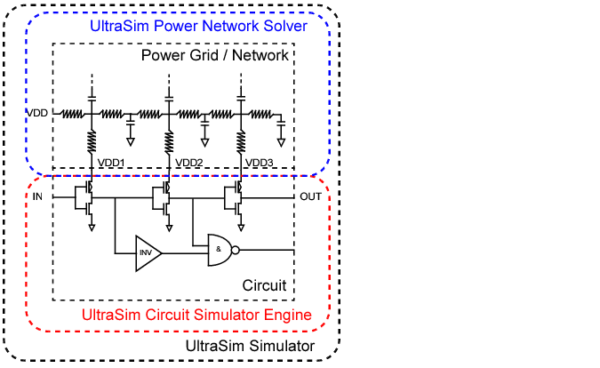
The UPS is an optimized solver designed to analyze linear power networks. The solver is integrated into the Virtuoso UltraSim simulator, and together with the Virtuoso UltraSim engine, lets you calculate the IR drop in power networks and analyze its effect on circuit behavior. Figure 6-1 shows an overview of the power network simulation methodology recommended by Cadence.
Figure 6-1 Overview of Power Network Simulation Methodology
The method=ups argument in the usim_pn command is used to enable UPS. Additional power network solver options can be set using the usim_ups keyword (see the table of "Arguments" for a list of usim_ups arguments).
|
Number of iterations between UPS and the Virtuoso UltraSim engine. The higher the iteration number, the greater the accuracy (default is iteration=1). The iteration argument only provides IR drop and does not calculate its influence on circuit behavior. To achieve higher accuracy for a large IR drop, Cadence recommends using iteration=2 or greater. |
|||||||
|
|||||||
|
Threshold peak for IR drop reporting (default print out is 20 nodes with highest peak IR drop). |
|||||||
|
Threshold RMS for IR drop reporting (default print out is 20 nodes with highest average RMS drop). |
|||||||
|
Prints out all power network node voltages (true) or the tap point connected to active devices (false). Default is false. Note: You first need to define waveform_file before all_waveform is enabled. |
|||||||
|
Filename that contains the nodes from the waveform file. Allows you to choose the nodes of interest. |
|||||||
Note: The UltraSim simulator only accepts one usim_ups statement at a time. If multiple usim_ups statements are specified in the netlist file, the simulator uses the last statement and ignores the rest.
usim_pn node=VSS_D pattern=[VSS_D] method=ups
usim_pn node=VSS_A pattern=[vss_a] method=ups
usim_ups iteration=1 speed=2 waveform_file=wave all_waveform=true
.usim_pn node=VSS_D pattern=[VSS_D] method=ups
.usim_pn node=VSS_A pattern=[vss_a] method=ups
.usim_ups iteration=1 speed=2 waveform_file=wave all_waveform=true
tells the Virtuoso UltraSim simulator:
For nodes associated with power net VSS_D, the simulator only partitions elements with terminal names containing VSS_D to be solved by UPS. For nodes associated with VSS_A, the simulator only partitions elements with terminal names containing vss_a to be solved by UPS. For nodes associated with VSS_D, the simulator only partitions elements with terminal names containing VSS_D to be solved by UPS.
|
|
The iteration number between the simulator engine and UPS is 1 (default), and speed is 2 (moderate speed and accuracy). |
|
|
All waveform files start with wave and they contain all of the power network nodes. |