The treats nets as Verilog-AMS wires from a discipline resolution point of view. The elaborator resolves wreal nets to either the digital or the analog domain based on how they are connected in the design and how the discipline resolution process propagates domain and disciplines up and down the design hierarchy.
Like Verilog-AMS wires, wreal nets can have any discipline (discrete or continuous) based on how they are declared, used, or resolved. To keep wreal signals in the discrete domain, use the ‑ams_dig_wreal option
Using default discipline resolution with a default discipline of logic, discrete nets that connect to wreal nets can become wreal nets. Consider the following example:
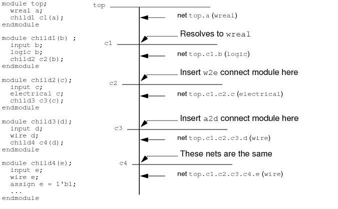
module top;
  wreal a;
  child1 c1(a);
endmodule

module child1(b) ;
  input b;
  logic b;
  child2 c2(b);
endmodule

module child2(c);
  input c;
  electrical c;
  child3 c3(c);
endmodule

module child3(d);
  input d;
  wire d;
  child4 c4(d);
endmodule

module child4(e);
  input e;
  wire e;
  assign e = 1'b1;
  ...
endmodule
According to the default discipline resolution where the default discipline is logic, nets top.a (a wreal) and top.c1.b (discrete net with discipline logic) are equivalent and top.c1.b resolves to a wreal (discipline logic).
Nets top.c1.b (discrete) and top.c1.c2.c (continuous) have incompatible disciplines (logic/wreal versus electrical) as do nets top.c1.c2.c and top.c1.c2.c3.d (electrical versus logic/wire) so the software needs to insert connect modules where these nets connect. The software determines which connect module to insert using connect rules. For example:
connectrules myrules;
  connect w2e input logic, output electrical;
  connect a2d input electrical, output logic;
endconnectrules
The port value type (wreal, electrical, logic) defines the selection of a connect module. The first connect rule above says to use the w2e connect module when connecting wreal (defaults to logic discipline) to electrical nets. The second connect rule above says to use the a2d connect module when connecting electrical to logic nets.
Nets top.c1.c2.c3.d and top.c1.c1.c3.c4.e are both discrete wires so the software does not need to insert connect modules here.
In the absence of unidirectional ports, the number of drivers on the wreal net determines the behavior of the connect module. For example, when an inout wreal connects to an inout electrical, you can use the function in the connect module definition to determine the number of drivers on the wreal net. If there are no drivers on the wreal net, the connect module does the conversion from electrical to wreal. (See Verilog-AMS wreal and Analog Signal Connections)
VHDL Blocks with Real Signal Ports on a Schematic
When you instantiate a VHDL block containing real signal ports on a schematic, you create a connection of VHDL real signals to Verilog-AMS wires from above. In such a situation, the simulator coerces the Verilog-AMS wire to become a digital wreal to integrate such VHDL blocks into the AMS flow.
AMS Designer resolves Verilog-AMS nets to the analog or digital domain during the discipline resolution process. AMS Designer does something similar with Verilog-AMS wires. When AMS Designer resolves to the digital domain, it is the digital simulator that handles the computations for that net.