In mixed-signal designs, you can connect nets to electrical nets, with either one on top, provided that appropriate connect modules are available to translate between signal types. For example, you can specify the following connection (wreal connected to electrical) when you have appropriate connect rules and modules available.
module top;
    wreal w;
    child c1(w); // wreal connected to electrical
endmodule

module child(e);
    input e;
    electrical e;
endmodule
When the wreal and electrical nets are connected, the port can be input, output, or inout.
The elaborator uses the signal type (wreal or electrical) to identify appropriate connect rules. For example, if myrule is defined as
connectrules myrule;
    connect a2d input electrical output logic;
    connect wreal_a2d input electrical output logic;
endconnectrules;
the domains and directions are insufficient to distinguish between the a2d rule and the wreal_a2d rule. If you add the information that the logic domain signal is actually wreal , the elaborator can select the connect module that has a wreal port of the appropriate direction.
You can find the E2R and R2E connect modules in the Cadence hierarchy:
your_install_dir/tools/affirma_ams/etc/connect_lib/E2R.vams
and
your_install_dir/tools/affirma_ams/etc/connect_lib/R2E.vams
These connect modules have appropriate port types and directions for use in connecting wreal nets to electrical nets. For example,
connectrules ConnRules_full_fast;
  connect L2E_2;
  connect E2L_2;
  connect Bidir_2;
  connect E2R;
  connect R2E;
  connect ER_bidir;
endconnectrules
In addition to connecting Verilog-AMS wreals to electrical nets, you can connect the SystemVerilog real ports to electrical nets.
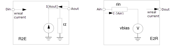
The basic, full, and full_fast R2E connect modules have been enhanced to support the current mode, in which electrical current is converted between wreal and electrical connection.
Following new parameters have been added to these connect modules to support wreal current. You can specify all the parameters in the ie card.
|
Parameter Name |
Default Value |
Description |
|---|---|---|
|
currentmode |
0 |
1 for wreal current |
|
clamp |
0 |
When set to 1, enables voltage clamp. It limits the signal voltage level to be within the supply voltage range, regardless of the value of the wreal current.
|
|
rin |
200 |
Current load resistance |
|
idelta |
10u |
Current delta of absdelta |
|
itoldelta |
|
Current tolerance of absdelta |
|
ix |
0 |
Current of wreal x |
|
vbias |
|
Bias voltage of current load |
|
vcclamp |
|
Voltage clamp zone |
You can create a customized connect rule CR_full_fast_current with discipline wreal_current and define wreal_current on applicable wreal ports of Verilog-AMS modules.
The current polarity of wreal port for wreal current modeling should be defined such that:
- For wreal input port, positive current means current flowing into the module.
- For wreal output port, positive current means current flowing out of the module.
Note that this wreal port current definition is different than the port current definition of Verilog-A/SPICE, in which positive current means current flowing into the module/subckt (regardless the port direction declaration if any).
With this wreal port current definition and the Verilog-A port current definition, the Electrical-Wreal connect modules in current mode are basically modeled as:
- R2E (input wreal Din, electrical Aout):
I(Aout) <- -Din; - E2R (electrical Ain, output wreal Dout):
Dout = I(Ain);
The following figures show the equivalent circuits for current-based connect modules: