- Software Requirements
- Technology Data Preparation
- Library and Technology Requirements
- Preparing the Technology Library
- Determining Whether Your MSOA PDK Is Traditional or Rapid
- Preparing the IP Library
- Creating a Rapid MSOA PDK with Multiple foundry_innovus Constraint Groups
- Preparing a Technology Library with Multiple LDRSs
- Rapid PDK ASCII Techfile Structure
3.1 Software Requirements
The following installations are required to build the flow. There are older versions of Innovus and Virtuoso which have also been qualified for the mixed-signal flow.
- Innovus Implementation System 17.1 or later with IC 6.1.6 ISR6 or later
3.2 Technology Data Preparation
This section contains the following:
- Library and Technology Requirements
- Preparing the Technology Library
- Preparing the IP Library
- Preparing a Technology Library with Multiple LDRSs
3.2.1 Library and Technology Requirements
- Technology and IP data on OpenAccess 2.2 Data Model 4 format
- A common (interoperable) Process Design Kit (PDK), which will have all the necessary technology information for Innovus and Virtuoso. For instruction on how to create a common PDK, please refer to the Preparing the Technology Library section.
- Liberty timing library for standard cells and IP blocks and chip-level SDC file. If you do not have Liberty files and the chip-level SDC file, it will not be possible to perform static timing analysis of the top-level design.
- Extended FE capacitance table and QRC technology file to support extraction in Innovus.
- Power analysis libraries for enabling VoltageStorm analysis in Innovus.
3.2.2 Preparing the Technology Library
Historically, most digital designs have relied on the use of a LEF file to specify the required technology information for the complete implementation of the design. These LEF technology files typically contain a complete set of rules for the metal and cut layers, and a very small subset of rules on the masterslice layers: poly, well, and diffusion.
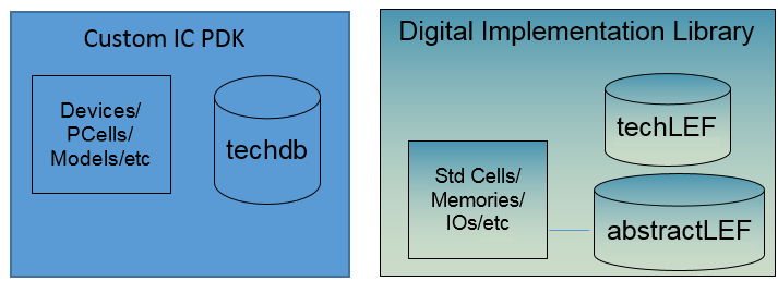
The use of the OpenAccess-based interoperable mixed-signal flow requires the implementation of a common OpenAccess Process Design Kit (MSOA PDK). The MSOA PDK contains the information typically found in a base PDK in addition to that found in the technology LEF. The base PDK, which is the PDK used for Virtuoso, is expected to have at least the foundry rules for the masterslice layers and will typically include the foundry rules for all the metal and cut layers. The LEF would have unique information not present in the PDK: Routing-specific information, such as default routing rules for most nets and non-default rules for selected nets. Default and non-default rules must include the list of valid routing layers and vias. The LEF language requires that routing pitch and width should be included. The LEF file also has antenna checking rules and current density limits, which could be defined in the PDK but is typically not found in a base PDK.
The following diagram shows the desired structure that must be built using the custom IC PDK and the digital implementation library shown above.
3.2.2.1 Implementing an Interoperable/MSOA PDK
As previously mentioned, interoperable PDKs are required to take advantage of OpenAccess-based interoperability for mixed signal designs. Starting from the 18.1 release of Innovus, you now have multiple options for creating an MSOA PDK:
- Rapid MSOA PDK (Available in 18.1 and later releases)
- Traditional MSOA PDK (Available prior to 18.1 and described above, these MSOA PDKs are supported only for 28nm and older nodes. If you are implementing a new MSOA PDK, Cadence recommends the implementation of a Rapid MSOA PDK.)
- Innovus-only MSOA PDK (Useful for experimenting with Innovus in the OpenAccess mode)
As discussed earlier, the process of creating an MSOA PDK involves populating the tech file used by Virtuoso (base tech) with specific information that is typically only found in a tech LEF (used for the P&R environment).
Implementing a Rapid MSOA PDK
This is the easiest method for creating an MSOA PDK that could be used by Innovus and Virtuoso to implement mixed signal designs. The Rapid MSOA infrastructure removes the necessity for all DRC rules to be consistent between tech LEF and Virtuoso tech for a certain process. In other words, there is no need to change the Virtuoso tech file to align the DRC rules in it with those found in the tech LEF. Virtuoso obtains all the DRC rules from the base tech (the same tech used by Virtuoso in the past), while Innovus gets DRC rules from an ITDB layer that contains all the rules found in the tech LEF.
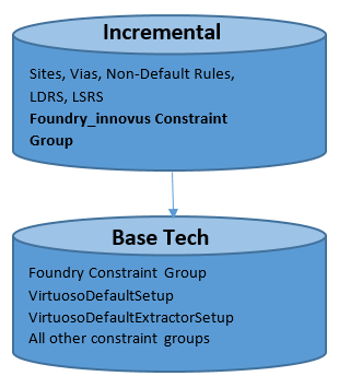
The main difference between the traditional MSOA PDK and the rapid MSOA PDK is the presence of a new foundry group in the incremental tech file, which will be used exclusively by Innovus for DRC rules.
The table below provide guidelines on the use of rapid MSOA PDKs:
|
Rapid |
Traditional** | |
|---|---|---|
|
Same as LEF from an Innovus point of view? |
Yes |
Yes |
|
Cellviews are interoperable with Virtuoso? |
Yes |
Yes |
|
OpenAccess tech supports Design Rule Driven (DRD) design and |
No |
Yes |
|
Target processes? |
New process nodes that are often changing |
Process nodes that are stable |
|
User who is expected to create the PDK? |
End users who receive frequent LEF updates |
Library vendors |
**Traditional MSOA PDKs are covered in detail in the next section.
You can follow the steps outlined below to implement a rapid MSOA PDK:
If Step 2 was not required, you can use the following command: Use Compare the LEF files from Step 5 against the ones from Step 1 or 2. The only differences should be that additional layers from the base PDK that were not in the original LEF will be present: If Step 2 was required, compare to the files from that step instead of Step 1. Use: Except the additional layers from the base PDK, there should be no differences, which indicates that Innovus should be able to produce identical results as compared to the flows using the the original LEFs.init_design:write_lef_library -tech_only and -macro_onlyTECH.lef and MACRO.lefset init_lef_file { <list_of_lef_files> }set init_verilog {list_of_verilog_files_or_dummy}
set init_top_cell <top_cell_name>init_designwrite_lef_library -tech_only TECH.lefwrite_lef_library -macro_only MACRO.lefLAYER/CUTCLASS/NDR names in the LEF are consistent with those in the base PDK. If not, use sed to create temp LEF file(s) that align to the LAYER/CUTCLASS/NDR names in the base PDK.
Note: Details and examples for this step are provided later in this document.lef2oa -useFoundryInnovus to process the TECH.lef (or the version created through the optional sed step).
lef2oa -useFoundryInnovus -lef TECH.lef -lib RapidPDK -techRefs BasePDK
If you had to use sed to rename certain items in Step 2, use the following command (here, the TECH_OA_NAMES.lef has been created using sed):lef2oa -useFoundryInnovus -lef TECH_OA_NAMES.lef -lib RapidPDK -techRefs BasePDKlef2oa to process the MACRO.lef:lef2oa -lef MACRO.lef -lib RapidPDK (If sed was not used) lef2oa -lef MACRO_OA_NAMES.lef -lib RapidPDK (If sed was used)
While importing the standard cell LEFs, ensure that the standard cells library does not have any existing cells with the same names. lef2oa cannot override physical data in the standard cell abstract views by default, so you might see the following message:WARNING: (OALEFDEF-50057): stdcell.lef (107464-107522) : MACRO XXXXXX: The macro attempts to redefine obstructions, but updating physical data is not supported. The new obstructions were ignored. Use the -overwrite option to create the designs from scratch.
If you want to recreate the abstracts for these cells, you need use either the -overwrite option of lef2oa or delete the cellview for these cells. However, note that it is possible to import the antenna information for an existing cell from a different LEF file by using lef2oa.
In some process nodes, the standard cells that are electrically equivalent (EEQ) come in multiple macro LEF files. For example, the macroB.lef file has a OR_SIZE1A_H100 standard cell that has the following EEQ statement:EQ OR_SIZE1_H100 ;while the cell OR_SIZE1_H100 is in the macroA.lef file.
To convert these macro LEFs into abstract, concatenate the two macro LEF files and then use lef2oa to read the concatenated file:cat macroA.lef macroB.lef > macroAB.leflef2oa -lef macroAB.lef -lib RapidPDK (If sed was not used)
Otherwise, if you use lef2oa to convert the macroB.lef file directly (lef2oa -lef macroB.lef -lib RapidPDK), lef2oa will fail and issue the following message when reading macroB.lef:ERROR: (OALEFDEF-50055): macroB(74-75) : MACRO OR_SIZE1A_H100: The macro requires that the EEQ master cell OR_SIZE1_H100 be defined before macro use. This attribute was ignored.init_design:write_lef_library -tech_only and -macro_onlyTECH_RapidPDK.lef and MACRO_RapidPDK.lefset init_oa_ref_lib { RapidPDK }set init_verilog { <list_of_verilog_files_or_dummy> }
set init_top_cell <top_cell_name>init_designwrite_lef_library -tech_only TECH_RapidPDK.lefwrite_lef_library -macro_only MACRO_RapidPDK.lefdiff TECH.lef TECH_RapidPDK.lef > TECH_RapidPDK.diffdiff MACRO.lef MACRO_RapidPDK.lef > MACRO_RapidPDK.diffdiff TECH_OA_NAMES.lef TECH_RapidPDK.lef > TECH_RapidPDK.diffdiff MACRO_OA_NAMES.lef MACRO_RapidPDK.lef > MACRO_RapidPDK.diff
As you can see, Steps 1-4 are for creating the rapid PDK, and Steps 5 and 6 are for checking the rapid PDK.
Details of Step 2 (using sed to create temp LEF file(s) that align to the LAYER/CUTCLASS/NDR names in the base PDK):
Simple sed syntax is used to make sure that only complete names are mapped. For example, M1 should be mapped to METAL1, but CM1 should not be affected by that mapping. The sed approach relies on the white space separated style that is used by the LEF/DEF syntax. It maps any complete name, so it will affect the names inside the property string values as well.
There are some limitation to the use of sed:
- If the LEF file contains names that need to be mapped that are also keywords, then extra processing is required.
Example: Mapping a layer calledPWELLtoPWwould affect theTYPE PWELLas well. - If the LEF and OpenAccess names are overlapping in some way:
Example 1: LEF hasM0,M1,M2, ...,M8and OpenAccess has layersM1,M2,M3...,M9To handle this case, the order of statements in thesedfile is important to prevent the layerM0from becomingM1, thenM2, thenM3, and so on, as thesedfile is processed (which happens sequentially). This is an unlikely perverse case, but is still easy to handle.
Example 2: LEF has CUTCLASS namesSQandRE, while the respective names in OpenAccess areVSINGLECUTandVDOUBLECUT. In addition, LEF has layersM1andVIA1, while the respective OpenAccess layers are calledMETAL1andVIA12as shown in the example below.
Example:
s/\<M1\>/METAL1/gs/\<VIA1\>/VIA12/gs/\<RE\>/VDOUBLECUT/gs/\<SQ\>/VSINGLECUT/g
In this case, the following syntax shoud be used:
s/\<lef_name\>/oa_name/g
The \< and \> are used to prevent partial matching.
To additionally handle the case where layer PWELL needs to be mapped to PW, the following syntax is required:
(lef_names_to_oa_names.sed)
s/\<TYPE PWELL\>/TYPE PWELL_temp/g
s/\<PWELL\>/PW/g
s/\<M1\>/METAL1/g
s/\<VIA1\>/VIA12/g
s/\<RE\>/VDOUBLECUT/g
s/\<SQ\>/VSINGLECUT/g
s/\<TYPE PWELL_temp\>/TYPE PWELL/g
Using sed to map OpenAccess names to LEF names:
To additionally handle the case where layer PW OR needs to be mapped to PWELL in LEF, the following syntax is required:
(oa_names_to_lef_names.sed)
s/\<TYPE PWELL_temp\>/TYPE PWELL/g
s/\<PW\>/PWELL/g
s/\<METAL1\>/M1/g
s/\<VIA12\>/VIA1/g
s/\<VDOUBLECUT\>/RE/G
s/\<VSINGLECUT\>/SQ/g
s/\<TYPE PWELL_temp\>/TYPE PWELL/g
The lines in Italic font are not actually required because the reverse mapping does not have the collision in this specific case.
The following are not covered by sed-based mapping:
- Special case mapping for LEF and OpenAccess semantic differences, such as:
- LEF
CM1 MASK1becomingCM1Ain OpenAccess R1(region layer) handling*_P48marker layer support
- LEF
- There is no scriptable workaround for the case where the same
CUTCLASSname is used for different layers, but the OpenAccess side has different names for each layer. The names need to be manually synced up in this case.
Creating a Traditional MSOA PDK
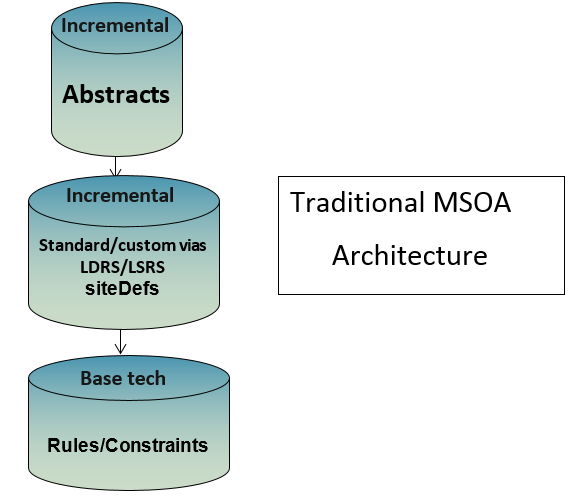
In the traditional MSOA architecture, the base library contains all the rules and constraints required to run the Virtuoso implementation environment. The same DRC rules will be used by Innovus, when it uses this technology library. An incremental technology library is created, which contains only the information needed to run the place and route (P&R) environment, such as any custom vias, the LefDefaultRouteSpec (LDRS) and the LefSpecialRouteSpec(LSRS), and the site definition for standard cells in the library. In order to run the P&R environment, Innovus uses abstracts of the standard cells. The standard cell OpenAccess abstracts are the additional incremental technology layer in the library.
Given that Innovus and Virtuoso will obtain technology information from the "Base tech" in the above diagram, there might be a need to reconcile any difference between the tech LEF and the tech DB prior to building the library illustrated above. The resulting MSOA PDK is referred to as a “Traditional MSOA PDK”.
It is recommended that you seek assistance from Cadence when creating MSOA PDKs for use in the Mixed Signal flow. The PDK factory team at Cadence is available to provide assistance and answer any questions you might have in creating and testing such PDKs. The process for creating traditional MSOA PDKs differs slightly based on the technology node for which the MSOA PDK is being implemented.
Creating a traditional MSOA PDK for process nodes 40nm or older
The process of creating a traditional MSOA PDK involves transferring data from the tech LEF and the Virtuoso tech to the MSOA PDK by following the arrows in the diagram below:
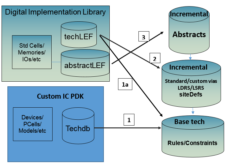
The numbers in the above diagram represent the sequence of actions needed to implement the traditional MSOA PDK.
For the above process to work well, you might be required to make updates to the following items in the Virtuoso technology file to reconcile any differences between the tech LEF and the Virtuoso tech file: Layer name and purposes, LPPs, capacitance and resistance information, current density information (if existing in Virtuoso tech), and advanced routing constraints. This is denoted as Step 1 and Step 1a in the above diagram.
Note that many foundries have started delivering Virtuoso tech files that are ready to go through Steps 2 and 3. You should contact the particular foundry to ask for an Innovus-ready Virtuoso tech file.
This method uses the lef2oa command in the Innovus hierarchy, and is targeted only at process nodes 40nm or older. Following is an example of how this command can be used to create an MSOA PDK:
lef2oa -lef <name_of_the_LEF_technology_file> -lib <the_MSOA_PDK_to_be_created> -techRefs <the_base_PDK> -pnrLibDataOnly
The above step extracts routing information, such as metal pitch, site definition, NDRs, vias, and so on, from the tech LEF and populates the information in the resulting MSOA PDK. In the diagram above, it is represented as Step 2.
Now you need to create an Incremental Technology Database (ITDB) structure for the standard cells and any macro libraries to be used with the MSOA PDK. This is also done using the lef2oa command as shown below:
lef2oa -lib <the_OA_stdcell_lib_to_be_created> -lef stdcell.lef -techRefs <the_MSOA_PDK_created_from_the_previous_step>
lef2oa -lib <the_marco_library_to_be_created> -lef macro/lef -techRefs <the_MSOA_PDK_created_from_the_previous_step>
Creating a traditional MSOA PDK for process nodes 28nm and below
The second method is to be used for 28nm and below. It involves the use of the write_oa_techfile command in Innovus to dump out an equivalent OpenAccess representation of the technology information found in the LEF technology file:
write_oa_techfile <filename>
After that is done, you can manually add the LEF information to the existing base PDK.
It is common to see a particular foundry update their existing 40nm or older LEF technology files to include rules that are typically found in newer processes. Pay special attention to warning and error messages when using the lef2oa command. If messages such as the one below are reported, you are advised to use the write_oa_techfile method to implement your interoperable MSOA PDK.
INFO: (OALEFDEF-XXXX): <path to the LEF file>(<line numbers in the LEF file>): A LEF58 property named 'XXXXXX' with value 'yyyy ;' was found in this line range. This property syntax is not supported by the LEF parser. This property string is kept, but is not converted into an OA rule constraint.
As can be seen from the above message, there will be a loss in the translation process to bring in the particular LEF information into the OpenAccess PDK.
Creating an Innovus-only MSOA PDK
Very often, users who have previously used Innovus in the LEF/DEF mode wish to try running the tool in the OpenAccess mode to better understand how the data is stored when Innovus is run in the OpenAccess mode. When Innovus is run in OpenAccess, the difference in the flow is basically in the initialization steps of the flow; the actual flow scripts that go through all the steps in the flow are identical to the LEF/DEF flow. In the OpenAccess mode, Innovus saves the data for the design into the same lib/cell/view structure that is used by Virtuoso to save the design data. This provides the end user with a unique interoperable environment, where a particular cell view could be opened in either Virtuoso or Innovus, edited, and the edits made available to the other tool.
If the end user is not interested in interoperating the design data between Innovus and Virtuoso and would only like to run Innovus in the OpenAccess mode, the MSOA interoperable PDK could be created using only the tech LEF data.
The detailed process for implementing an MSOA PDK for use only by Innovus is as follows:
-
Invoke EDI or Innovus with any design that uses the LEF technology information in which you are interested. Then, invoke
write_oa_techfile. This command writes out a DFII style ASCII technology file that can later be given to thetechLoadDumpexecutable to create an equivalent OpenAccess technology database. -
In the same EDI/Innovus session, run the following command:
write_lef_library -tech_only
This command creates a LEF file that contains only the LEF technology information. This file will be used in later tasks in this process. - In the same EDI/Innovus session, run the following command:
write_lef_library -macro_only
This command will write out the LEF information for macros in the LEF library. This information will get used by later tasks in this process. -
The next command is available in the Virtuoso hierarchy. Ensure that you have access to the installation you want to use for this step. Invoke the following command with the file created from Step 1:
techLoadDump -l -createLib <library_name> <tech_file_from_Step1>.
This command will create an OA library with LEF layers and foundry rules, from the ASCII technology file that was created by thewrite_oa_techfilecommand.
Note: For advanced node processes (14nm and below), thetechLoadDumputility from a Virtuoso Advanced Node (ICADV*) Release must be used.You can use the
techLoadDumpcommand from the UNIX prompt for both loading or dumping a technology library.$ which techLoadDump/INSTALL/IC618ISR/tools/dfII/bin/techLoadDump$ techLoadDumpVirtuoso Framework License (111) was checked out successfully. Total checkout time was 0.09s.Usage: techLoadDump [ -l | -d ] [-createLib [-libPath libPath]] techLibName techFileNameFor creating a technology library, use the
-lparameter.For dumping a techlib, use the
-dparameter.You can also load or dump a tech file for a given library by using the Tools -> Technology File Manager command from CIW in Virtuoso. This opens the Techology File Manager form, which provides options to load or dump a technology file.
- The next command is available in the EDI/Innovus installation hierarchy. You will be using the output of Step 2 as input for this command. Invoke:
lef2oa -pnrLibDataOnly -lef <file_from_Step2> -techRefs <library_created_from_Step4> -lib <library_name>.
This command maps only library-specific place and route information to an incremental tech, ignoring foundry rules. The incremental technology database references a technology database that has complete foundry information. LEF constructs DIRECTION and PITCH, along with WIDTH, OFFSET, and WIREEXTENSION (if specified) are mapped to constraints in theLEFDefaultRouteSpec(LDRS) type constraint group. VIAS and VIARULES defined are added to the validRoutingVias constraint in theLEFDefaultRouteSpec. NONDEFAULTRULES are mapped to OpenAccess constraint groups, SITES are mapped to oaSiteDefs, and MACROS are mapped to abstract oaDesigns. For more information on this command, refer to the Innovus Text Command Reference manual. - Now that the library has all the rules, the abstracts need to be added to the library to complete the process. In EDI/Innovus, invoke the following command:
lef2oa -lef <file_from_step3> -lib <library_created_in_Step5>
3.2.2.2 Recommended Method for Checking the Integrity of the Common/Interoperable PDK for Innovus
After you have implemented an interoperable PDK, it is recommended that you perform the following steps to ensure that the LEF technology related information contained in the PDK is the same as the information contained in the initial LEF file that was used to create the interoperable PDK. The verification method involves writing the LEF related information out of the PDK and comparing it to the initial LEF. The steps are as follows:
- Start Innovus with the interoperable OA PDK, which contains the LEF technology information.
- Use the Innovus command
write_lef_libraryto output a LEF file from the interoperable OA PDK. Note that this command outputs a LEF directly from the Innovus DB, and is an exact representation of how the LEF technology data is seen by Innovus. - Start Innovus again with the original LEF that was used to make the interoperable PDK.
- Use the Innovus command
write_lef_libraryto output a LEF file. - As the output of
write_lef_libraryis in a canonical format, you can now use the Unix commandtkdiffto compare the two.
You can also dump out the PDK technology into an ASCII file from Virtuoso to check if all the rules names and values are defined correctly in the appropriate sections. This will enable you to check the mapping of the rules from the LEF file to their corresponding OpenAccess structure. To do so:
- In the Virtuoso Command Interpreter Window (CIW), choose Tools -> Technology File Manager -> Dump.
- From the Technology Library drop-down list, select the interoperable PDK and then select the Select All check box to indicate you want to dump out all rules.
- Specify a name for the file in the ASCII Technology File text box and click OK.
For more information on the ASCII techfile syntax and the Rapid PDK ASCII syntax in particular, refer to the Rapid PDK ASCII Techfile Structure section.
3.2.3 Determining Whether Your MSOA PDK Is Traditional or Rapid
The Innovus command report_oa_lib can be used to determine the type of MSOA PDK technology library being used in the Innovus session.
innovus> report_oa_lib <libName>
The output of this command will be similar to the following:
Library Name        : FEOAreflib

cdsinto.tag exists     : No

Compression Level      : 0

Rapid PDK : Yes

Constraint Groups      : 6
 Library Name: FEOAreflib
  LEFDefaultRouteSpec (LEFDefaultRouteSpec, default)
   validLayers: M1 M2 M3 M4 M5 M6 AP
   validVias: VIAGEN12 VIAGEN23 VIAGEN34 VIAGEN45

  minSpacing
  minNumCut
  minProtrusionNumCut
  oaMinViaSpacing_FEOAreflib
  LEFSpecialRouteSpec

Technology Graph:
 FEOAreflib
If the MSOA PDK is a Rapid MSOA PDK, the report will contain the following line:
Rapid PDK : Yes
On the other hand, if the MSOA PDK you are using is traditional, the report will contain the following line:
Rapid PDK : No
3.2.4 Preparing the IP Library
-
For opening a design in Innovus, ensure that the IP library contains the abstract views of all IP blocks used at the top level in the design.
While opening an existing OpenAccess design database, Innovus uses the
init_oa_ref_liblist and theinit_abstract_viewvariable values given in the configuration file to read the existing abstract view. - If the
SYMMETRYattribute is not set, you can set the symmetry of a cell using the following SKILL commands in the CIW window of Virtuoso XL:cv = geGetWindowCellView(hiGetCurrentWindow())dbSetCellViewSymmetry(cv "XYR90")dbGetCellViewSymmetry(cv)
- If you require the analog property, add the analog property
oacSigTypeAnalogon analog nets so that Innovus maintains such nets asdbIsAnalog true. This is an optional step.
To add the analog property (signal type) in Virtuoso, follow these steps:- Right-click the top-most toolbar to invoke the Navigator and the Property Editor.
- Expand Navigator Nets to view all the nets.
- Select the net for which you want to change the signal type.
- Save the design.
- To generate abstracts for analog IPs that are finally used by Innovus, use Virtuoso Abstract Generator. Virtuoso Abstract Generator preserves the
oacSigTypeAnalogon terminal nets in the OpenAccess database. - Save the OpenAccess database of IP abstracts to be used by the digital toolsets. Use verilogAnnotate, a stand-alone UNIX utility, to annotate the bus terminal list and order the distributed terms in the physical abstract. The verilogAnnotate utility can be found in the Virtuoso installation hierarchy.
Run the following command:verilogAnnotate -refLibs <> -verilog <>
If using Virtuoso Layout XL, use the following settings instead of theverilogAnnotatecommand:envSetVal("layoutXL" "createImplicitBusTerminals" 'boolen t)
When you create abstracts in Virtuoso Abstract Generator, use:absSetOption( "AnnotateBusInAbstract" "true")
UseverilogAnnotateonly if you have some legacy IPs that cannot not be modified by any other way. - Unset the environment variable
OA_HOME. Ensure that theOA_HOMEenvironment variable is not set before running Virtuoso XL/GXL or Innovus. Source the Virtuoso path setting file so that you can get Virtuoso XL/GXL in yourPATHenvironment variable. - Follow these steps to open the design with parameterized cell (PCell) in Virtuoso XL/GXL, and regenerate the PCell cache:
- Choose Tools-Express Pcell Manager.
- Enter the details and enable caching of Pcell check box using the Auto Save option.
- Click Save Copy to save the PCell layout cache.
This step enables interoperation of data between Innovus and Virtuoso platforms. Close the layout window and purge your data from Virtuoso so that the Virtuoso file lock is released. For more information, see the Virtuoso XL/GXL User Guide.
3.2.5 Creating a Rapid MSOA PDK with Multiple foundry_innovus Constraint Groups
A foundry may release multiple tech LEF files corresponding to the same Virtuoso PDK. In the past, you had to create a Rapid MSOA PDK for each tech LEF. The MSOA PDK creation process has been enhanced in 21.13 release of Innovus to allow for the creation of a single Rapid MSOA PDK, containing multiple foundry_innovus constraint groups, each corresponding to a tech LEF.
This process is not recommended if the tech LEF files have any of the following conditions:
- Different siteDefs with the same name exist in the tech LEF files.
- Vias with the same name, but different geometries, exist in the tech LEFs.
- LEF NDRs with the same name, but different width, spacing, or other attributes, exist in the tech LEFs.
- Cut classes with the same name, but different sizes, exist in the tech LEFs.
The process for creating such a Rapid MSOA PDK is as follows:
- Create the base technology library, if it does not already exist, from the base ASCII tech file using either the Technology File Manager in Virtuoso or the
techLoadDumpexecutable. Refer to the Creating an Innovus-only MSOA PDK section for details of this process. - Run the following
lef2oacommands to create a multi-tech Rapid PDK fromtechLEF_6andtechLEF_9. This step can be extended to any number of LEF files.lef2oa -lef techLEF_6.lef -lib myfoundry_innovus -techRefs myfoundry -logFile lef2oa_run1.log -useFoundryInnovus -suffix _6
This firstlef2oacommand uses-techRefsto reference the base PDK; any subsequentlef2oaruns do not need the-techRefsoption. The abovelef2oacommand creates the firstfoundry_innovusconstraint group with the namefoundry_innovus_6.lef2oa -lef techLEF_9.lef -lib myfoundry_innovus -logFile lef2oa_run2.log -useFoundryInnovus -suffix _9The abovelef2oacommand creates a secondfoundry_innovusconstraint group with the namefoundry_innovus_9. This constraint group corresponds totechLEF_9.
The previous two steps create a Rapid PDKmyfoundry_innovus, which has the respective constraint groups named with the specified suffixfoundry_innovus_6,foundry_innovus_9,LEFDefaultRouteSpec_6and so on.
-
Convert the standard-cell and macro LEFs to OpenAccess while referencing to the Rapid PDK created in the above step. For more details on this step, see the Implementing a Rapid MSOA PDK section.
- Set the following commands in Innovus to read the corresponding tech from the multi-tech Rapid PDK. For example, to read
foundry_innovus_6from the Rapid MSOA PDK, set the following commands while importing the design into Innovus. Similarly, forfoundry_innovus_9, replace_6with the_9.set init_oa_default_rule LEFDefaultRouteSpec_6set init_oa_foundry_rule foundry_innovus_6set init_oa_special_rule LEFSpecialRouteSpec_6
- Check the library with
report_oa_libto make sure that you can see all thefoundry_innovusconstraint groups that needed to be created. - Validate using the
write_lef_libraryoutput to check if the corresponding technology information is read correctly.
While creating a multi-tech Rapid MSOA PDK, the ITDB may have multiple cut classes, not all of which will be required for a single tech set. Starting from the 21.17 release, a new constraint cutClassNames is added in each foundry_innovus_<suffix> to store the sizes of the cutClasses needed for a specific layer. Only the cutClasses specified in this constraint will be read into Innovus.
3.2.6 Preparing a Technology Library with Multiple LDRSs
This process will work only for a traditional MSOA PDK. You should not follow these instructions if the MSOA PDK being created is a Rapid MSOA PDK.
As previously discussed in this document, a LEFDefaultRouteSpec (LDRS) is a constraint group that gets added to the Virtuoso tech file for use by Place and Route tools, such as the Virtuoso Space Based Router, the Innovus Placement Engine, and the Innovus Router NanoRoute. The LDRS contains the same information as that can be found in a tech LEF file. The LDRS can contain information on routing layers, default vias, pitch, routing direction and width, layer offset, and wire extension rule. The rest of the rules are read from the foundry constraint group in the tech.
In some cases, you may wish to have one tech file with multiple LDRSs. For example, you may want certain designs to use different widths or routing directions for optimal results while all other designs follow the regular LDRS. In this case, the original LDRS and the modified LDRS could both exist in the tech file. When the tech file is used with Innovus, you can instruct Innovus to pick the correct LDRS by using the following setting:
init_oa_default_rule ruleName
Note that the second LDRS should be given a unique name because that is what tells Innovus which LDRS to choose for a particular Innovus session. The tech file needs to be edited to add the second LDRS. If the contents of the tech file is dumped to ASCII, the LDRS will look similar to this example:
;********************************; CONSTRAINT GROUPS;********************************constraintGroups(
;( group [override] [definition] [operator] ) ;( ----- ---------- ------------ ---------- ) ( "LEFSpecialRouteSpec" nil "LEFSpecialRouteSpec"
interconnect( ( validVias (M2_M1 M3_M2 M4_M3 M5_M4 M6_M5 M7_M6 M8_M7 M9_M8 M10_M9 M11_M10 ) ) ) ;interconnect ) ;LEFSpecialRouteSpec
;( group [override] [definition] [operator] ) ;( ----- ---------- ------------ ---------- ) ( "LEFDefaultRouteSpec" nil "LEFDefaultRouteSpec"
routingDirections( ( Poly "none" ) ( Metal1 "horizontal" ) ( Metal2 "vertical" ) ( Metal3 "horizontal" ) ( Metal4 "vertical" ) ( Metal5 "horizontal" ) ( Metal6 "vertical" ) ( Metal7 "horizontal" ) ( Metal8 "vertical" ) ( Metal9 "horizontal" ) ( Metal10 "vertical" ) ( Metal11 "horizontal" ) ) ;routingDirections
spacings( ( minWidth "Cont" 0.06 ) ) ;spacings
routingGrids( ( horizontalPitch "Metal1" 0.2 ) ( verticalPitch "Metal1" 0.19 ) ( horizontalOffset "Metal1" 0.1 ) ( verticalOffset "Metal1" 0.095 ) ) ;routingGrids
spacings( ( minWidth "Metal1" 0.06 ) ( minWidth "Via1" 0.07 ) ) ;spacings
routingGrids( ( horizontalPitch "Metal2" 0.2 ) ( verticalPitch "Metal2" 0.19 ) ( horizontalOffset "Metal2" 0.1 ) ( verticalOffset "Metal2" 0.095 ) ) ;routingGrids
spacings( ( minWidth "Metal2" 0.08 ) ( minWidth "Via2" 0.07 ) ) ;spacings
routingGrids( ( horizontalPitch "Metal3" 0.2 ) ( verticalPitch "Metal3" 0.19 ) ( horizontalOffset "Metal3" 0.1 ) ( verticalOffset "Metal3" 0.095 ) ) ;routingGrids
spacings( ( minWidth "Metal3" 0.08 ) ( minWidth "Via3" 0.07 ) ) ;spacings
routingGrids( ( horizontalPitch "Metal4" 0.2 ) ( verticalPitch "Metal4" 0.19 ) ( horizontalOffset "Metal4" 0.1 ) ( verticalOffset "Metal4" 0.095 ) ) ;routingGrids
spacings( ( minWidth "Metal4" 0.08 ) ( minWidth "Via4" 0.07 ) ) ;spacings
routingGrids( ( horizontalPitch "Metal5" 0.2 ) ( verticalPitch "Metal5" 0.19 ) ( horizontalOffset "Metal5" 0.1 ) ( verticalOffset "Metal5" 0.095 ) ) ;routingGrids
spacings( ( minWidth "Metal5" 0.08 ) ( minWidth "Via5" 0.07 ) ) ;spacings
routingGrids( ( horizontalPitch "Metal6" 0.2 ) ( verticalPitch "Metal6" 0.19 ) ( horizontalOffset "Metal6" 0.1 ) ( verticalOffset "Metal6" 0.095 ) ) ;routingGrids
spacings( ( minWidth "Metal6" 0.08 ) ( minWidth "Via6" 0.07 ) ) ;spacings
routingGrids( ( horizontalPitch "Metal7" 0.2 ) ( verticalPitch "Metal7" 0.19 ) ( horizontalOffset "Metal7" 0.1 ) ( verticalOffset "Metal7" 0.095 ) ) ;routingGrids
spacings( ( minWidth "Metal7" 0.08 ) ( minWidth "Via7" 0.07 ) ) ;spacings
routingGrids( ( horizontalPitch "Metal8" 0.2 ) ( verticalPitch "Metal8" 0.19 ) ( horizontalOffset "Metal8" 0.1 ) ( verticalOffset "Metal8" 0.095 ) ) ;routingGrids
spacings( ( minWidth "Metal8" 0.08 ) ( minWidth "Via8" 0.07 ) ) ;spacings
routingGrids( ( horizontalPitch "Metal9" 0.2 ) ( verticalPitch "Metal9" 0.19 ) ( horizontalOffset "Metal9" 0.1 ) ( verticalOffset "Metal9" 0.095 ) ) ;routingGrids
spacings( ( minWidth "Metal9" 0.08 ) ( minWidth "Via9" 0.18 ) ) ;spacings
routingGrids( ( horizontalPitch "Metal10" 0.5 ) ( verticalPitch "Metal10" 0.19 ) ( horizontalOffset "Metal10" 0.6 ) ( verticalOffset "Metal10" 0.095 ) ) ;routingGrids
spacings( ( minWidth "Metal10" 0.22 ) ( minWidth "Via10" 0.18 ) ) ;spacings
routingGrids( ( horizontalPitch "Metal11" 0.5 ) ( verticalPitch "Metal11" 0.475 ) ( horizontalOffset "Metal11" 0.6 ) ( verticalOffset "Metal11" 0.57 ) ) ;routingGrids
spacings( ( minWidth "Metal11" 0.22 ) ) ;spacings
interconnect( ( validLayers (Metal1 Metal2 Metal3 Metal4 Metal5 Metal6 Metal7 Metal8 Metal9 Metal10 Metal11 ) ) ( validVias (M2_M1_HV M2_M1_VV M2_M1_VH M2_M1_HH M2_M1_2x1_HV_E M2_M1_2x1_HV_W M2_M1_1x2_HV_N M2_M1_1x2_HV_S M3_M2_VH M3_M2_HH M3_M2_HV M3_M2_VV M3_M2_M_NH M3_M2_M_SH M3_M2_2x1_VH_E M3_M2_2x1_VH_W M3_M2_1x2_VH_N M3_M2_1x2_VH_S M4_M3_HV ) ) ) ;interconnect ) ;LEFDefaultRouteSpec) ;constraintGroups
If the user wishes to add a second LDRS, the ASCII tech file needs to be edited to include the name of the additional LDRS and any specific data that is typically found in the LDRS. In the example below, LEFDefaultRouteSpec_3H is a new LDRS added to an existing tech that already contains a default LDRS.
;********************************; CONSTRAINT GROUPS;********************************constraintGroups(
;( group [override] [definition] [operator] ) ;( ----- ---------- ------------ ---------- ) ( "LEFSpecialRouteSpec" nil "LEFSpecialRouteSpec"
interconnect( ( validVias (M2_M1 M3_M2 M4_M3 M5_M4 M6_M5 M7_M6 M8_M7 M9_M8 M10_M9 M11_M10 ) ) ) ;interconnect ) ;LEFSpecialRouteSpec
;( group [override] [definition] [operator] ) ;( ----- ---------- ------------ ---------- ) ( "LEFDefaultRouteSpec" nil "LEFDefaultRouteSpec"
.
.
.
..
) ;LEFDefaultRouteSpec
( "LEFDefaultRouteSpec_3H" nil
.
.
.
) ;LEFDefaultRouteSpec_3H
Note that the second LDRS (LEFDefaultRouteSpec_3H) did not need to be defined as a LEFDefaultRouteSpec, as Innovus will search the tech for the name specified using the following command:
init_oa_default_rule LEFDefaultRouteSpec_3H
3.2.7 Rapid PDK ASCII Techfile Structure
The basic sections of the ASCII technology file are mentioned below. The Rapid PDK will not have all the sections defined fully as it will create only the technology data from the LEF and use basic data, such as layer names, from the base PDK.
controls: This section has the general information for the PDK, such as the grid and technology reference libraries, along with the parameters that can be used across the technology library.layerDefinitions: This section has the user-defined layer and purpose definitions along with the display setup. Most of the layer definitions are part of the base PDK.layerRules: This section contains the layers function, the routing direction, the cutClasses and so on among other attributes for user-defined layers. The layer function is defined in the base PDK, but the cutClasses are defined in both the base and the Rapid PDK.viaDefs: This section contains all the standard and custom via definitions. Both the base and the Rapid PDK can have their own via definitions.constraintGroups: This section stores most of the technology rules for the layers. While Virtuoso reads in most of the technology rules from thefoundrysection in the base PDK, the Rapid PDK creates thefoundry_innovussection, which has most of the LEF technology rules to be read in by Innovus.siteDefs: This section has the site definitions for the PDK. The sites can be defined in either the base or Rapid PDK.
Click here to view a sample of an ASCII techfile skeleton.
3.2.7.1 Key Subsections in the Rapid PDK ASCII Technology file
The primary sections mentioned above have various subsections to manage the information easily. Let's look at some of the key subsections in the Rapid PDK ASCII technology file in more detail.
-
The
refTechLibssubsection in thecontrolssection: The name of the reference technology library of the Rapid PDK is seen in therefTechLibssubsection of thecontrolssection. This subsection contains the name of the base PDK that is being referred by the Rapid PDK. All the layer names, layer functions, and display patterns for the layer purpose pairs are picked up from this base PDK. Example:
refTechLibs(; techLibName; --------- "basePDKName") ;refTechLibs
-
The
LEFDefaultRouteSpecconstraint group in theconstraintGroupssection: This constraint group captures the plance-and-route (PnR) information, such as specific information on the valid routing layers and the default via definitions needed by Innovus. The valid vias can also have the standard via definitions which can be used by Innouvs to create the required variants. This section also has the following technology rules specific to these PnR layers:-
Layer direction for the routing layers. The routing direction can also be pre-defined in the base PDK in the
routingDirectionssubsection of thelayerRulessection. -
The minWidth for the routing layers
-
The routing pitch for the routing layers
-
The routing offset for the routing layers
-
The wire extension for the routing layers
-
The width and pitch for the 45-degree angle style routing
Here's an example of the
LEFDefaultRouteSpecconstraint group in theconstraintGroupssection:constraintGroups(
;( group [override] [definition] [operator] )
;( ----- ---------- ------------ ---------- )
( "LEFDefaultRouteSpec" nil "LEFDefaultRouteSpec"
routingDirections(
( M1 "horizontal" )
( M2 "vertical" )
...
) ;routingDirections
routingGrids(
( horizontalPitch "M1" 0.2 )
( verticalPitch "M1" 0.19 )
( horizontalOffset "M1" 0.1 )
( verticalOffset "M1" 0.095 )
) ;routingGrids
spacings(
( minWidth "M1" 0.06 )
) ;spacings
...
...
interconnect(
( validLayers ( M1 M2 M3 M4 M5 M6 ) )
( validVias ( M2_M1 M3_M2 M4_M3 M5_M4 M6_M5 ))
) ; interconnect
) ;LEFDefaultRouteSpecYou can have multiple
LEFDefaultRouteSpecconstraint groups in the tech graph and specify the one from which rules are to be read. Use the following variable to control the name of theLEFDefaultRouteSpecto be read:set init_oa_default_rule <LDRS_CG_name> -
-
The
foundry_innovusconstraint group in theconstraintGroupssection: Thefoundry_innovusconstraint group captures all the technology rules for all the layers defined in the LEF file apart from the rules that are defined in theLEFDefaultRouteSpec. This section basically recreates all the LEF technology rules in the ITDB for use of Innovus without any dependency on the foundry section of the base PDK. All the LEF58 layer and library properties from the LEF file are also stored within this section.
Innovus reads this section to populate the technology rules in its database. Thelef2oaprocess might create several other constraint groups, such asminSpacing,minDualExtension, and so on and add them as member constraint groups within thefoundry_innovusgroup.
On the other hand, Virtuoso, by default, reads the technology rules from thefoundryconstraint group of the tech graph for all its applications.
You can have multiplefoundry_innovusconstraint groups in the tech graph and specify the one from which rules are to be read. Use the following variable to control the name of thefoundry_innovusconstraint group to be read:set init_oa_foundry_rule <foundry_CG_name>Here's an example of the
foundry_innovusconstraint group in theconstraintGroupssection:;( group [override] [definition] [operator] )
;( ----- ---------- ------------ ---------- )
 ( "foundry_innovus" nil "foundry_innovus"
...
spacings(
...
   ( layerProp    "M1" 'propName "LEF58_ANTENNAGATEPLUSDIFF" "ANTENNAGATEPLUSDIFF OXIDE1 0.350 ; ANTENNAGATEPLUSDIFF OXIDE2 0.350 ;" )
   ( layerProp    "M1" 'propName "LEF58_MINSTEP" "MINSTEP 0.10 MAXEDGES 1 MINADJACENTLENGTH 0.10 ;" )
   ( layerProp    "M1" 'propName "LEF58_RECTONLY" "RECTONLY ;" )
   ( layerProp    "M1" 'propName "LEF58_RIGHTWAYONGRIDONLY" "RIGHTWAYONGRIDONLY ;" )
   ( minWidth     "M1"    0.024 )
   ( maxWidth     "M1"    0.25 )
   ( minArea      "M2"    0.00288 )
   ( minEndOfLineSpacing    "M2"   (0.0405 0.0135 0.06) )
  ) ;spacings
memberConstraintGroups(
...
"minSpacing"
...
); memberConstraintGroups
spacingTables(
;( constraint layer1 [layer2]
; (( index1Definitions [index2Defintions]) [defaultValue] )
; ( table) )
;( --------------------------------------------)
( minDensity "M1"
...
( maxDensity "M1"
)
) ;spacingTables -
The
LEFSpecialRouteSpecconstraint group in theconstraintGroupssection: TheLEFSpecialRouteSpec(LSRS) is used primarily for power routing. It is used to list the viaDefs that should be used at a particular width intersection. It is equivalent to the list of LEF VIARULE statements in LEF.
However, Innovus can use any standardViaDef, even the ones not listed in the LSRS for routing.
Earlier, the via generator used to determine the viaDef to be used on the basis of the order in the LSRS but now priority is given to the cut area and the viaDef that creates the largest cutArea is used.
To restrict the via choice,setViaGenMode -viarule_preference <list of valid vias>should be used.
Here's an example of theLEFDefaultRouteSpecconstraint group in theconstraintGroupssection:;( group [override] [definition] [operator] )
;( ----- ---------- ------------ ---------- )
( "LEFSpecialRouteSpec" nil "LEFSpecialRouteSpec"interconnect(
( validVias (
(( "layer1Width" nil nil "layer2Width" nil nil )
'viaLayerDirection
(
...
...
) ;LEFSpecialRouteSpecYou can have multiple
LEFSpecialRouteSpecconstraint groups in the tech graph and specify the one from which rules are to be read. Use the following variable to control the name of theLEFSpecialRouteSpecto be read:set init_oa_special_rule <LSRS_CG_name> - The non-default rules (NDRs) in the
constraintGroupssection: Separate constraint groups are created for all the NDRs defined in the LEF files and these NDRs are available for use in Innovus. Example:;( group [override] )
;( ----- ---------- )
( "CTS_Rule" nil
spacings(
...
( minSpacing "M2" 0.13 'soft )
( minSpacing "M1" 0.13 'soft )
( minWidth "M1" 0.13 )
( minWidth "M2" 0.14 )
...
) ;spacings
interconnect(
( validLayers (M1 M2 M3 M4 M5 ) )
( validVias (VIA12_HV VIA23_VH VIA34_VH VIA45_VH ) )
) ;interconnect
spacingTables(
;( constraint layer1 [layer2]
; (( index1Definitions [index2Defintions]) [defaultValue] )
; ( table) )
;( --------------------------------------------)
( minNumCut "V1"
(( "minNumCut" nil nil ) 1)
...
)
...
) ;spacingTables
) ;CTS_Rule -
The cutClass definitions in the
layerRulessection: All the cutClasses defined in the LEF file are added to the ITDB structure. The difference in name with the cutClasses in the base PDK does not matter as long as the width, length and numCuts parameters are in sync with the base PDK. Example:cutClasses(
Note: Even if the name or number of the cutClasses is different in the base PDK and the Rapid PDK, Innovus would always be reading the cutClasses defined in the Rapid PDK. Therefore, a LEF dump from Innovus with the Rapid PDK would show up the same cutClasses as in the technology lef file. However, to avoid any complications, it is recommended that you should keep the names and definitions of the cutClasses in the technology LEF file the same as those in the base PDK while creating the Rapid PDK.
;( layerName )
;( (cutClassName (width length)) )
;( ------------------------------------------------ )
(V1
(VSQ 'numCuts 1 (0.016 0.016))
(VREC 'numCuts 2 (0.016 0.03))
)
(V2
(VSQ 'numCuts 1 (0.016 0.016))
(VREC 'numCuts 2 (0.016 0.03))
)
...
...
) ;cutClasses -
The via definitions in the
viaDefssection: The via definitions from the LEF file, both custom and standard, are also created in the ITDB structure. However, the standard vias from both the base PDK and the Rapid PDK are available to be used in Innovus. Example:viaDefs(
standardViaDefs(
;( viaDefName layer1 layer2 (cutLayer cutWidth cutHeight [resistancePerCut])
; (cutRows cutCol (cutSpace) [(l_cutPattern)])
; (layer1Enc) (layer2Enc) (layer1Offset) (layer2Offset) (origOffset)
; [implant1 (implant1Enc) [implant2 (implant2Enc) [well/substrate]]])
;( ----------------------------------------------------------- )
( M2_M1 M1 M2 ("V1" 0.07 0.07 5.0)(1 1 (0.07 0.07))
(0.005 0.03) (0.005 0.03) (0.0 0.0) (0.0 0.0) (0.0 0.0)
)
( M3_M2 M2 M3 ("V2" 0.07 0.07 5.0)(1 1 (0.07 0.07))
(0.005 0.03) (0.005 0.03) (0.0 0.0) (0.0 0.0) (0.0 0.0)
)
...
) ;standardViaDefs
customViaDefs(
;( viaDefName libName  cellName viewName layer1 layer2 resistancePerCut)
;( ---------- -------  -------- -------- ------ ------ ----------------)
 ( M2_M1     RapidPDK  M2_M1      via      M1     M2    0.0)
 ( M3_M2     RapidPDK  M3_M2      via      M1     M2    0.0)
...
...
) ;customViaDefs - The site definitions in the
siteDefssection: The site definitions for the standard cells are also saved in thesiteDefssection of the ITDB techfile. Example:siteDefs(
Note: The site definitions are read in from all the libraries specified in the reference library list during the
scalarSiteDefs(
;( siteDefName type width height symInX symInY symInR90)
;( ----------- ---- ----- ------ ------ ------ -------)
( CoreSite core 0.2 1.71 nil t nil)
( PadSite pad 240.0 240.0 nil nil nil)
) ;scalarSiteDefs
) ;siteDefsinit_designstep in Innovus. So, if some of the sites are not defined in the technology graph (ITDB structure) but are read from any reference library, they would be saved in the design library. However, duringrestoreDesign, it is expected that the site definitions are part of the technology graph and are not read from the reference libraries. - The
FIXEDMASKstatement in thefoundry_innovusconstraint group in theconstraintGroupssection: TheFIXEDMASKstatement from the LEF file is mapped to thecolorControlsection of the ASCII tech file in the foundry group. It is set in thefoundry_innovusconstraint group in case the base PDK foundry constraint group does not have this set.( "foundry_innovus" nil
...
colorControl(
( integrationColorModel "locked" )
) ;colorControl
...
) ;foundry_innovus
3.2.7.2 Mapping for Other Key Rapid PDK Constructs
Mapping for the LEF Library Properties
The LIBRARY PROPERTYDEFINITIONS from the LEF file are mapped to libProp in the foundry_innouvs subsection of the ASCII techfile. They are also set as properties on the Rapid PDK library.
Note: If any libProp definitions are found in the Rapid PDK while reading the OpenAccess data to Innovus, the properties set on the library are ignored.
Here's a sample mapping of the LIBRARY PROPERTYDEFINITIONS in the LEF file to the ASCII techfile:
| LEF File Section | ASCII Techfile Syntax |
|---|---|
PROPERTYDEFINITIONS LIBRARY LEF58_FINFET STRING " FINFET PITCH 0.056 OFFSET 0.0 HORIZONTAL NOCORECELL ; " ; END PROPERTYDEFINITIONS |
( "foundry_innovus" nil "foundry_innovus" ... ( libProp 'propName "LEF58_FINFET" " FINFET PITCH 0.056 OFFSET 0.0 HORIZONTAL NOCORECELL ; " ) ... ) ;foundry_innovus |
You can check the LIBRARY PROPERTYDEFINITIONS from the Library Manager in Virtuoso. To do so:
- Choose CIW -> Library Manager.
- In the listing of the libraries, right-click the name of the Rapid PDK tech library and select Properties from the context menu.
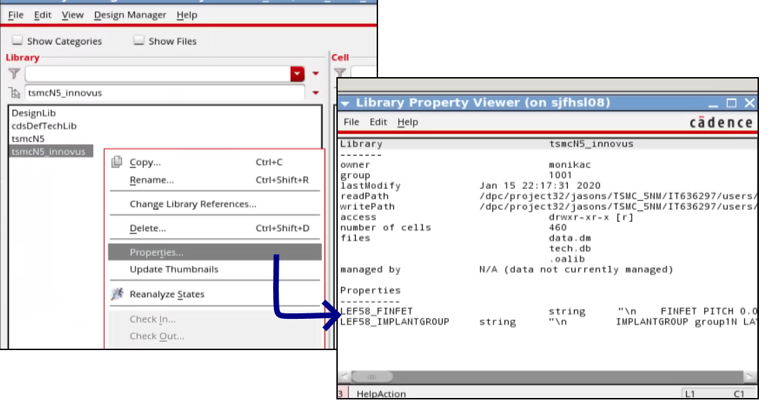
Note: All the properties in the base and Rapid PDKs are read into Innovus. However, if a property with the same name exists in both the base and Rapid PDKs, only the version from the Rapid PDK is read into Innovus.
Checking for Layer Names, Definitions, and Number of Masks
- The layer names between the base PDK and the technology LEF file must match. In case of any mismatches, fix the technology LEF using a sed script or the vi editor to match the names with the base PDK before creating the Rapid PDK structure.
- This layer name change would also be needed for the standard cell and NDR LEF files.
- All the layer definitions must exist in the base PDK; any new layers defined in the LEF file will be dropped during the
lef2oaprocess. - If a layer has multiple masks, ensure that the mask number has the same value defined in both the base PDK and the technology LEF file. In case of a mismatch, the number of masks defined in the base PDK will be kept and the LEF mask number will be ignored.
Here is a sample section from the base PDK with the layer definitions and number of masks per layer values:
layerDefinitions(

techLayers(
;( techLayer number abbreviation [#Masks] )
;( --------- ------ ------------ -------- )
...
 (  M1        31      M1          2 )
 (  M2        32      M2          2 )
...
) ;techLayers
...
) ;layerDefinitions
Note: Pseudo-material layers, such as routing, cut, and trimmetal, for the region-based rules (Example: M1_FB1) do not need to be defined in the base PDK; these are created in the rapidPDK_techLibName.
Checking for Routing Layer Usage and Routing Direction
- Ensure that there is no mismatch between the LEF file and the base PDK in the layer type definition or usage (for example, whether a layer is used as metal, cut, masterslice and so on).
lef2oawill give an error if the type in the LEF file does not match the type specified in the base PDK.
Note: However, if the base PDK has a particular type set, the LEF can be used to update the subclasses of the same type. For example, if the base PDK has a layer with type CUT, the LEF can have the TYPE as IMPLANT and that will be updated. Similarly, for a type routing in the base PDK, the type can be overridden in the tech LEF file. - Ensure that the routing direction for the metal layers is also the same between the LEF file and the base PDK.
Here is a sample section from the base PDK with the layer functions:
layerRules(
  functions(
;( layer  function  [maskNumber] )
;( -----  --------  ------------ )
...
 ( M1    "metal"    104 )
 ( VIA1  "cut"      107 )
 ( M2    "metal"    108 )
...
  ) ;functions

  routingDirections(
  ;( layer    direction )
  ;( -----    --------- )
...
   ( M1       "vertical" )
   ( M2       "horizontal" )
...
  ) ;routingDirections
...
) ;layerRules
Checking for the OALAYERMAP Definition for Layers with Multiple Masks
The LEF58_OALAYERMAP construct defined in the techfile can be used to map a layer with multiple masks to different layer names. This is supported only for trim metal layers. You need to make sure that the layermap definition is not repeated in the technology LEF file in case it is already defined in the base PDK.
Consider an example in which the MASK 1 shapes on LEF layer CL1 would go to the OpenAccess layer CL1A while the MASK 2 shapes on CL1 would go to the OpenAccess layer CL1B. In this case:
- Ensure that the layer
CL1is not defined in the base PDK as that can cause issues with the tool since the shapes will be created on different layers based on the mask number. - The layer
CL1needs to be defined in the technology LEF file, whereas the layersCL1AandCL1Bneed to be defined in the base PDK, as shown below.
| LayerMap in the Base Virtuoso techfile | controls( |
|---|---|
| LEF File Definition | LAYER CL1 |
3.2.7.3 ASCII Techfile Skeleton
; Technology File myTechLib
; Generated on MM DD HR:MIN:SEC YYYY
; with @(#)$CDS: techLoadDump version BUILDVERSION MM/DD/YYYY HH:MM (machineName) $
controls(
         ...
techParams(
...
         ) ; techParams
         ...
) ; controls
layerDefinitions(
...
                 techLayers(
                 ...
) ;techLayers
...
) ;layerDefinitions
layerRules(
...
functions(
...
) ;functions
...
cutClasses(
...
) ; cutClasses
...
) ; layerRules
viaDefs(
...
standardViaDefs(
...
) ; standardViaDefs
...
customViaDefs(
...
) ; customViaDefs
) ;viaDefs
constraintGroups(
...
( "foundry"
...
) ;foundry
...
) ; constraintGroups
siteDefs(
...
scalarSiteDefs(
...
) ; scalarSiteDefs
) ;siteDefs