Create Stranded Wire Form
The Create Stranded Wire command is used to create a wire comprising multiple strands in a single direction on a single net.
|
Field
|
Description
|
|
Net Name
|
Specifies a net name for the current stranded wire. The stranded wire is added to the specified net. A new net is created if the one specified does not exist.
Environment variable: netName
|
|
Probe Nets
|
Creates probes for the selected or specified net (Layout XL and higher tiers).
|
|
Parameters
|
This section lets you specify the width, direction, and style for the wire that you want to create.
|
|
Strand Width
|
Specifies the width of each strand in the stranded wire.
|
|
Strand Number
|
Specifies the number of strands in each stranded wire.
|
|
Strand Spacing
|
Specifies the spacing between the individual strands of the stranded wire.
|
|
Begin Style
|
Controls how the stranded wire segment begins.
-
auto: Automatically sets the begin style of the stranded wire.
-
When the stranded wire is Manhattan in shape, its Begin Style is set to truncate.
-
Two orthogonal Manhattan wires will have their Begin Style and End Style set to extend in order to avoid notches.
-
When the stranded wire is diagonal in shape, its Begin Style is set to custom.
-
Two diagonal orthogonal stranded wires will have their Begin Style and End Style set to custom in order to avoid notches.
-
truncate: Creates a stranded wire with no begin extension.
-
extend: Creates a stranded wire with the default beginning extension value.
-
variable: Lets you override the value specified in the Begin field for the begin extension of a stranded wire.
-
custom: Creates a stranded wire in which the vertices are constrained to the current grid.
The default value is auto.
Environment variable: pathSegBeginStyle
|
|
Begin
|
Specifies the value for the begin extension of the stranded wire. This field is enabled when Begin Style is set to variable.
Environment variable: pathSegBeginExt
|
|
End Style
|
Controls how the beginning wire segment ends are created.
-
auto: Automatically sets the end style of the wire.
-
When the stranded wire is manhattan in shape, its Begin Style is set to truncate.
-
Two orthogonal manhattan stranded wires will have their Begin Style and End Style set to extend in order to avoid notches.
-
When the stranded wire is diagonal in shape, its End Style is set to custom.
-
Two diagonal orthogonal stranded wires will have their Begin Style and End Style set to custom to avoid notches.
-
truncate: Creates a stranded wire with no begin extension.
-
extend: Creates a stranded wire with the default begin extension value.
-
variable: Lets you override the value specified in the Begin field for the begin extension of a wire.
-
custom: Constraints the vertices of the created wire to the current grid.
The default value is auto.
Environment variable: pathSegEndStyle
|
|
End
|
Specifies the value for the end extension of the stranded wire. This field is enabled when End Style is set to variable.
Environment variable: pathSegEndExt
|
|
Creation Mode
|
The following options let you specify the snapping behavior for the stranded wire that you want to create.
|
|
Snap Mode
|
Controls how the cursor snaps when you create the stranded wire.
-
orthogonal: Creates wires parallel to the X or Y axis. This is the default option.
-
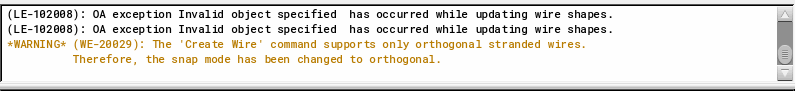
diagonal: Generates a warning message informing the user that only orthogonal stranded wires are supported. The mode is automatically changed to orthogonal.
Environment variable: snapMode
|
|
Auto Terminate
|
Finishes the Create Stranded Wire command as soon as a point is digitized on a flightline target object (pin or existing wire or via). When creating a stranded wire and Auto Terminate is on, all stranded wires snap to its target pin. This option is selected by default.
|
Related Topics
Working with Stranded Wires
Return to top