Some analog operations can be directly implemented in wreal and others need a real translation. The following are a few standard tasks that are needed during wreal modeling:
Wreal Value Sources
How can we generate sources with values varying over time? The following example is a source for an analog amplifier that we discuss later on. It creates a differential signal on the output ports P and N.
A real value (Vin) is used to assign different values to it after certain delays. Discrete events are created on the real value, for example, at 150 ps the value is changing from 0.108 to 0.15. At 300 ps, a sinusoidal signal is generated. The loop is updated every 20 ps with a new value generated by the sin function. Note that we need to define the sampling time for these types of continuous signals. Wreal is changing at discrete events, thus, a continuous signal needs to be approximated by a given sampling rate. The appropriate sampling rate and the decision on using a fixed or a flexible time step depend on the sampled signal and the accuracy requirements for the following blocks.
The real value is assigned to the wreal outputs P and N is a symmetrical way.
`include "constants.vams"`include "disciplines.vams"`timescale 1ps/1ps
module wrealAmp_stim (P,N);output P,N;wreal P,N;
real Vin; // input voltagereal Freq=600M,Phase=0; // sinusoid params
initial begin // drive input, comment on expected result: Vin=0.1; // out=1 for DC op point #50 Vin=0.108; // out=1.08 in <20ps #100 Vin=0.15; // out=1.5 in 100ps #150 Vin=0.5; // out sat=3.0 in 300ps #400 Vin=0; // out=0 in 600ps #700 Vin=0.2; // out=2.0 after 400ps, but: #300 Vin=0.1; // prior to full change, ramp down to out=1 #300 while ($abstime<6000p) begin // generate ramped sine input#20 Freq=Freq*1.007; // gradual freq increasePhase=Phase+20p*Freq; // integrate freq to get phaseif (Phase>1) Phase=Phase-1; // wraparound per cycleVin=0.1*(1+sin(`M_TWO_PI*Phase)); // sinusoidal waveform shapeend#200 $finish; // done with testend
assign P = Vin/2; // drive symmetric diffl signal to inputsassign N = -Vin/2;endmodule
Integration and Differentiation
The following example shows an analog integration and differentiation on a given sinusoid input function.
`include "disciplines.vams"`timescale 1ns/1ns
module top (); electrical x, idt_x, ddt_x;
w_idt I_w_idt (x); w_ddt I_w_ddt (x);
analog begin V(x) <+ sin($abstime*1E7); V(ddt_x) <+ ddt(V(x)); V(idt_x) <+ idt(V(x),0); endendmodule // top
The same input waveform is converted into a wreal signal using the E2R connect rules with a 0.1 V accuracy.
connectrules e2r_only; connect E2R #( .vdelta(0.1), .vtol(0.001), .ttol(1n));endconnectrules
The two sub modules implement the integration and differentiation function in the discrete domain. The only information needed in addition to the input signal is the time point of the last event (lasttime) and the value at this time (lastval). The time difference between the last event and the current time determines the integration interval for this particular step. A simple multiplication with the last wreal input increments the integral values. The initial condition for the integral is set to 0.0.
module w_idt(w_x); input w_x; wreal w_x, w_idt_x; real r_idt_x = 0; real lasttime = 1; real lastval = 0;
always begin if (lasttime < $abstime) begin r_idt_x = r_idt_x + lastval * ($abstime - lasttime); end lasttime = $abstime; lastval = w_x; @(w_x); end assign w_idt_x = r_idt_x;endmodule
The differentiation operator is implemented very similarly. Dividing value by the time difference gives the derivative of the last step. Note that this is the linear interpolated derivative over the given time period.
module w_ddt(w_x); input w_x; wreal w_x, w_ddt_x; real r_ddt_x = 0; real lasttime = 1; real lastval = 0;
always begin if (lasttime < $abstime) begin r_ddt_x = (w_x - lastval) / ($abstime - lasttime); end lasttime = $abstime; lastval = w_x; @(w_x); end assign w_ddt_x = r_ddt_x;endmodule
It should be considered that the step size of the wreal events highly influences the derivative calculation. Large steps can lead to inaccurate values. Moreover, the differentiation and integration function will update only when a wreal event occurs. For example, if you were calculating the integral of a constant value you would not get any results because there is only one event on the wreal signal at time point zero. In such cases, you need to sample the input signal appropriately, for example, by the fix rate sampling shown above.
The w_idt function implements the integral of the wreal signals sample and hold behavior while the w_ddt assumes a linear interpolation. It is a matter of which definition concept you follow. Generally, the sample and hold behavior is more digital-like while the linear interpolation is closer to the analog signal nature. If you want to integrate wreal as linear interpolated signal, a trapezoidal integration of the values would be more appropriate. This would result in:
r_idt_x = r_idt_x + 0.5 * (w_x + lastval) * ($abstime - lasttime);
The differentiation of the sample and hold interpretation of the signal results in a Dirac pulse, which is not useful for most models.
Value Sampling
Wreal signals are event-based. They can have a fixed sampling rate or the step size from one event to another can vary from step to step. During the conversion from a continuous domain into the discrete wreal domain, events are created based on the amount of value change. Even inside the event-based simulation, it is often necessary to change the sampling rate from one block to another.
The following example shows a triangular step wave input signal that should be sampled at a lower rate. We implemented two different sample modules to show the different behavior.
//xrun sampler.vams -gui -access r`include "constants.vams"`include "disciplines.vams"`timescale 1ns / 1psmodule top ( s_out ); output s_out; wreal s_out, s_sample, s_sample_simple; real r_out;
fix_rate_sampler #(.sr(200M)) I_frs (s_out, s_sample); fix_rate_sampler_simple #(.sr(200M)) I_frss (s_out, s_sample_simple);
always begin repeat (5) begin r_out = 0.0; #1 r_out = 1.0; #1 r_out = 2.0; #1 r_out = 3.0; #1 r_out = 4.0; #1; end $finish; end assign s_out = r_out;endmodule
The first module is a very simple sampling module that is triggered at the given sampling rate. At this point in time, it takes the wreal input signal, samples it and holds the value until the next sample time.
A limitation of this simple mechanism is that every event on the real input signal between the sampling times is completely ignored. If you simulate the example, you see that the outcome of the sampler is always 4.0 because it happens to sample the input wave on the 4.0 step. This obviously does not reflect the real behavior very well.
module fix_rate_sampler_simple (s_in, s_out ); input s_in; wreal s_in; output s_out; wreal s_out; real r_out, ts;
parameter sr = 1M; // sampling rate in Hz
initial begin ts= 1.0E+9/sr; // in ns end
always #ts begin r_out = s_in; end assign s_out = r_out;endmodule
The following sampling block is a bit more advanced. It integrates the input signal over the period between the sampling steps. Thus, all events of the real signal are taken into account. The simulation shows that the output values results in 2.0, which is the time average of the input signal. The block also considers wrealXState and wrealZState input values. Whenever one of these values occur the output value follows this assignment.
module fix_rate_sampler (s_in, s_out );input s_in;wreal s_in;output s_out;wreal s_out;
parameter sr = 1M; // sampling rate in Hz
// Input signal averageing based on sampling timereal T_begin, s_integ;real T_last, s_last;real ts;real avg_out;
// initialize all values to zeroinitial begin s_integ = 0; s_last = 0; T_begin = 0; T_last = 0; ts= 1.0E+9/sr; // in nsend
always @(s_in) begin if (s_last === `wrealXState)begin s_integ = `wrealXState;end else if ((s_last === `wrealZState) && (s_integ !== `wrealXState))begin s_integ = `wrealZState;end else begin // if s_in is a normal value // collecting the value*time integral s_integ = s_integ + s_last*($abstime-T_last);end T_last=$abstime; // save the time of the current event s_last=s_in; // save the value end // always @ (s_in)
always #ts begin // add the last missing time periode to the integral if (s_last === `wrealXState)begin s_integ = `wrealXState; avg_out = `wrealXState;end else if ((s_last === `wrealZState) && (s_integ !== `wrealXState))begin s_integ = `wrealZState; avg_out = `wrealZState;end else if ((s_integ !== `wrealZState) || (s_integ !== `wrealXState))begin // if s_in is a normal value // collecting the value*time integral s_integ = s_integ + s_last*($abstime-T_last); avg_out = s_integ/($abstime-T_begin); // calc averageend T_last=$abstime; // same the current time s_last=s_in; // and value T_begin = $abstime; // reset time interval s_integ = 0; // reset integral end assign s_out = avg_out;endmodule
Slew Limiting
Digital systems mostly react instantaneously on input changes or they might have some delay until the output response is visible. However, analog systems mostly have a limited rise and fall time, which means when a signal changes from 0.0 V to 3.3 V it takes a certain amount of time for this change. During this period, the signal – more or less – linearly rises to the final value. This effect is called slew limit. The maximal rise value per time is called slew rate.
Describing this fundamental analog behavior in the discrete domain is not trivial. A single event causes a series of other events to mimic the linear ramp. We need to control the number of steps that are created for the ramp carefully. Too many events will slow down the simulation unnecessarily while fewer events will be not accurate enough.
The following example is an amplifier that limits the output values and the output slope. The testbench provides a set of different input signals.
`include "constants.vams"`include "disciplines.vams"`timescale 1ps/1psmodule top(); wrealAmp_stim stim (P,N); wrealAmp amp (P,N, OUT);
endmodule // top
module wrealAmp_stim (P,N);output P,N;wreal P,N;
real Vin; // input voltagereal Freq=600M,Phase=0; // sinusoid params
initial begin // drive input, comment on expected result: Vin=0.1; // out=1 for DC op point #50 Vin=0.108; // out=1.08 in <20ps #100 Vin=0.15; // out=1.5 in 100ps #150 Vin=0.5; // out sat=3.0 in 300ps #400 Vin=0; // out=0 in 600ps #700 Vin=0.2; // out=2.0 after 400ps, but: #300 Vin=0.1; // prior to full change, ramp down to out=1 #300 while ($abstime<6000p) begin // generate ramped sine input#20 Freq=Freq*1.007; // gradual freq increasePhase=Phase+20p*Freq; // integrate freq to get phaseif (Phase>1) Phase=Phase-1; // wraparound per cycleVin=0.1*(1+sin(`M_TWO_PI*Phase)); // sinusoidal waveform shapeend#200 $finish; // done with testend
assign P = Vin/2; // drive symmetric diffl signal to inputsassign N = -Vin/2;endmodule
The amplifier calculates the nominal output value first based on the input and the given limit values. The second always block is responsible to apply the slew limit to the output. The maximum change in value that can be performed depends on the step size since the last event. If the nominal output value change is smaller than this value (dvlast) the change can be applied directly to the output.
Larger changes are limited to the given maximum change value and new events are being created with the given step size of tstep. The output is stepping up/down until the nominal output value is reached.
// Wreal amplifier with added slew limiting of output signal.// Input does not require equally spaced timepoints.// The output waveform will add timepoints at the specified// tstep spacing when needed to simulate slewing behavior. `include "constants.vams"`include "disciplines.vams"`timescale 1ps/1psmodule wrealAmp (P,N,OUT); input P,N; output OUT; wreal P,N,OUT; parameter real vio=0, gain=10; // input offset voltage (V), // gain (V/V) parameter real voh=3, vol=0; // output voltage range (V) parameter real slewrate=5G; // max output slew rate (V/sec) parameter real tstep=20p; // timestep for slew ramp (sec) real Vnom,Vslew; // nominal output, and slew real dtstep,dvstep; // time & voltage max step size real tlast=0,dvlast; // last timepoint, and // max dV of last step always begin // compute nominal output value Vnom <= min(voh,max(vol,gain*(P-N-vio))); // linear gain with hard clip @(P,N); // repeat when input changes end
always begin // slew limit the output signal if ($abstime==0) dvlast = voh-vol; // no step limit at DC else dvlast = slewrate*min($abstime-tlast,tstep); // max prev step tlast = $abstime; // save event time if (abs(Vnom-Vslew) <= dvlast) begin // If change within +-dV range: Vslew = Vnom; // step to new value @(Vnom); // and wait for Vnom to change end
else if (Vnom>Vslew) begin // Perform slew limit, rising: Vslew = Vslew+dvlast; // limit max change. #(tstep/1p); // and wait for timestep end
else begin // Perform slew limit, falling: Vslew = Vslew-dvlast; // limit change per step. #(tstep/1p); // and wait for timestep end
end assign OUT = Vslew; // drive wreal output valueendmodule
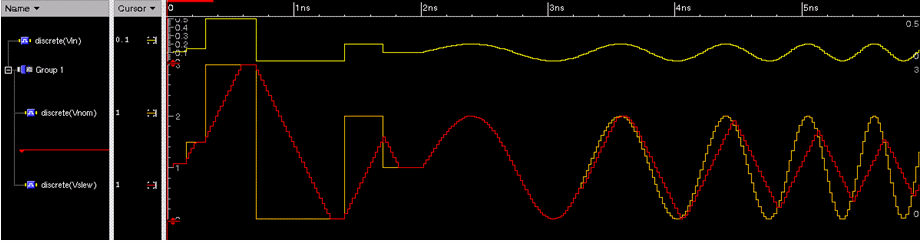
The following figure shows the input and output waveform of the slew limited filter. It is shows how the red output signal is not able to follow the input signal. It is ramping up or down linearly with the given slew rate.