5
Specifying Label Information
- Interpreted Labels Information
- The Annotation Setup Form
- Creating Labels with SKILL
- Complex Pole Example
- NFET Example
Interpreted Labels Information
You can use interpreted labels to display parameter values, evaluated parameter values, net connectivity information, backannotated simulation information, and more.
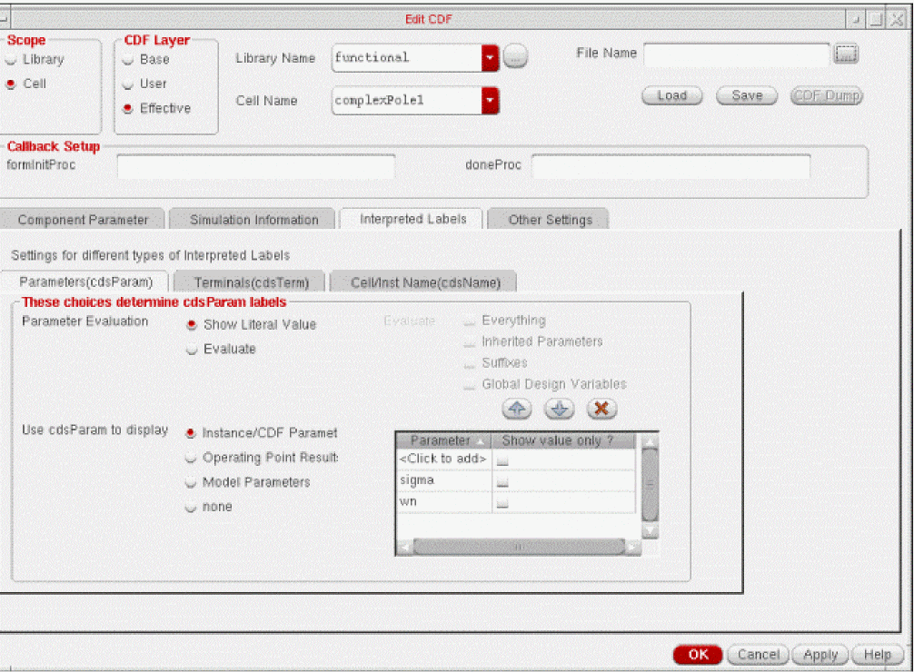
You can set the default label display options in the Interpreted Labels tab of the Edit CDF form. The Interpreted Labels tab has the following three tabs that are described below:
Library label information differs from cell label information. So the display that you see in Parameters(cdsParam), Terminals(cdsTerm) and Cell/Inst Name(cdsName) tabs depends on whether you are viewing the CDF for a library or a cell. For more information about the tabs, see the following sections.
Parameters(cdsParam)
The cdsParam( ) labels (usually placed on the layer annotate drawing) display information about parameter values or backannotated parameter values. You can set the default display options for cdsParam labels in the Parameters(cdsParam) tab.
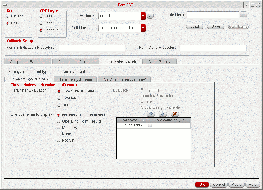
The fields in the Parameters(cdsParam) tab are described below:
-
Parameter Evaluation
selects a method for displaying parameter values. (These different methods of display are necessary because a parameter value can be a constant, a design variable, an expression using constants or design variables, or a value or expression inherited from the hierarchy.)
- Show Literal Value displays the literal parameter value as entered.
- Evaluate evaluates the parameter value as specified in the Evaluate field.
- Not Set enables you to specify a value of not set for any field. This means that the parameter is deleted from or not added to the base-level library CDF. The corresponding value of the parameter is picked from the library level for any field on the Interpreted Labels tab.
-
Evaluate
selects the parameter evaluation method if Parameter Evaluation is set to Evaluate. Select the check box next to one of the following options:
- Everything performs complete numeric evaluation of the expression and displays the result. For example, if the value is Rin*10 and Rin is 5, it displays 50. If the value is pPar(Rin)*100 and the parent instance has a parameter Rin set to 10, it displays 1000.
- Inherited Parameters evaluates inherited parameters in expressions. For example, if the value is pPar(Rin)*100 and the parent instance has a parameter Rin set to 10, the label displays 10 * 100.
- Suffixes converts suffixes in the parameter value to numerical values. For example, 1K becomes 1000.
- Global Design Variables evaluates global design variables in expressions. For example, if the value is Rin*100 and Rin is 5, the label displays 5 * 100.
-
Use cdsParam to display
allows you to select the kind of parameters to display for cells.
- Instance/CDF Parameter displays the instance or CDF parameters listed in the table. For information about selecting the parameters to be displayed, see Specifying cdsParam Parameters to Display.
- Operating Point Result displays the DC or transient operating point results from simulation for the parameters listed in the table. For information about selecting the parameters to be displayed, see Specifying cdsParam Parameters to Display.
- Model Parameters displays the simulation values for the model parameters listed in the table. For information about selecting the parameters to be displayed, see Specifying cdsParam Parameters to Display.
- None displays no parameters
-
Not Set
specifies that you made no selection for this field
- Operating Point Results Type selects the simulation type for the operating point result that you want to annotate. The choices are DC or Transient. This field is for operating point parameters only.
Terminals(cdsTerm)
The cdsTerm( ) labels (usually placed on the layer annotate drawing8) display information about the pin or about the nets attached to the pin. You can set the default display options for cdsTerm labels in the Terminals(cdsTerm) tab.
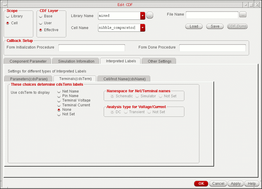
The fields in the Terminals(cdsTerm) tab are described below:
- Use cdsTerm to display selects what is displayed next to the component terminals.
- Namespace for Net/Terminal names selects the type of net name to display if Use cdsTerm to display is set to Net Name or Pin Name. The choices are Schematic, Simulator, or Not Set.
- Analysis type for Voltage/Current selects the simulation type for the result that you want to annotate.The choices are DC, Transient, or Not Set. This field is used only when Use cdsTerm to display is either Terminal Voltage or Terminal Current.
Cell/Inst Name(cdsName)
The cdsName( ) labels (usually placed on the layer annotate drawing7) display information about the cell name or the instance name. You can set the default display options for cdsName labels in the Cell/Inst Name(cdsName) tab.
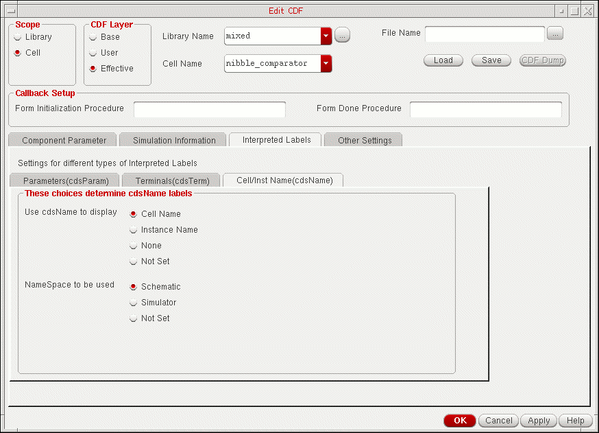
The fields in the Cell/Inst Name(cdsName) tab are described below:
- Use cdsName to display selects what is displayed next to the component symbol.
- NameSpace to be used selects the type of instance name. The choices are Schematic, Simulator, or Not Set. This field is used only when the Use cdsName to display is Instance Name.
Creating Labels Using the Edit CDF Form
You can make selections for label information for both library and cell CDFs. You can use the following procedure to create labels for a library CDF.
- Click the Interpreted Labels tab of the Edit CDF form.
- Make edits for library or cell CDF label specifications.
- Click Apply to apply these specifications to the current CDF.
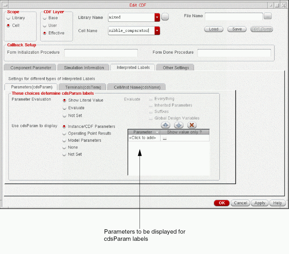
Specifying cdsParam Parameters to Display
The Parameters(cdsParam) tab on the Interpreted Labels tab of the Edit CDF form allows you to specify the parameters to be displayed for cdsParam labels.
To specify the cdsParam parameters to display, do the following:
-
Select the radio button corresponding to the parameters you want to display—Instance/CDF Parameter, Operating Point Result or Model Parameters.
The table on the right lists the parameters to be displayed. For example, the table in the following figure lists the parameters to be displayed if the Instance/CDF Parameter radio button is selected.
-
Specify the parameters you want to display:
-
To add a parameter, click where it says <Click to add> in the Parameter column and type the name of the parameter.
-
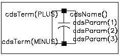
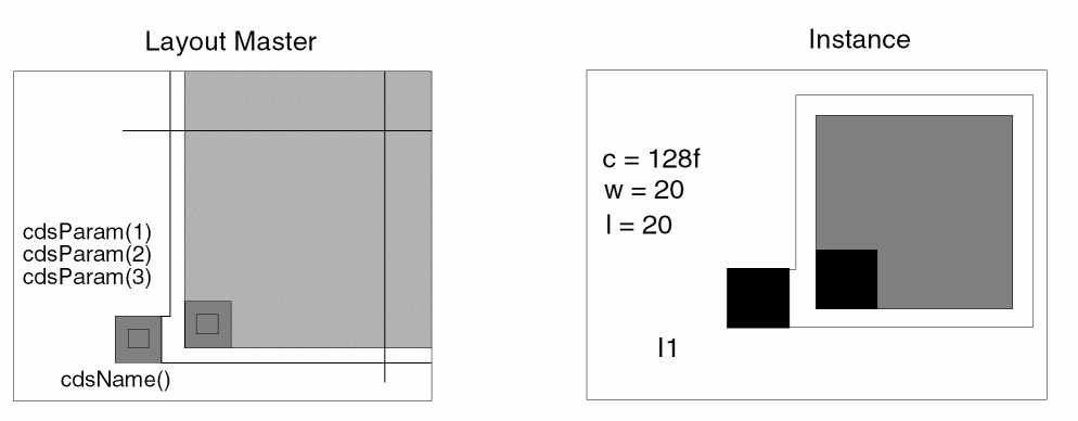
The parameters are displayed in the order in which they are listed in the table. The number of parameters that are displayed is also limited to the number of cdsParam labels on the cell. For example, the following figure shows the symbol for a capacitor that has three cdsParam labels. For this cell, only the first three parameters listed in the table are displayed.To change the order in which the parameters are listed in the table, select a parameter and click the
 or
or  buttons.
 -
By default, a parameter name and its value are displayed in the format:
parameter name
:value
To display only the value of a parameter, select the check box next to the parameter in the Show Value Only ? column. -
To delete a parameter, select the parameter and click the
 button.
-
To add a parameter, click where it says <Click to add> in the Parameter column and type the name of the parameter.
- Click Apply.
The Annotation Setup Form
You can control the creation of CDF labels by using the View – Annotations – Setup command in the Schematic to open the Annotation Setup form.
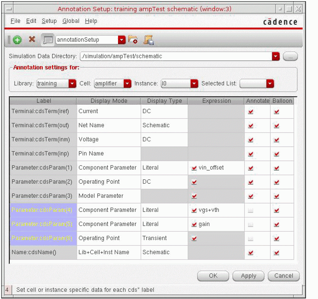
When you change the display of information in the Annotation Setup form, the display of ilLabels (labels generated automatically during automatic symbol generation) and interpreted labels is affected. ilLabels are usually defined on symbols and are displayed when you place the symbol in a schematic. For example, the following figure shows the symbol for a capacitor from analogLib:
The cdsTerm( ) labels (usually placed on the layer annotate drawing8) display information about the pin or about the nets attached to the pin. These labels must follow the syntax cdsTerm(pinName). In the Annotation Setup form, you can use the Terminal:cdsTerm() label settings to control the cdsTerm labels.
The cdsName( ) labels (usually placed on the layer annotate drawing7) display information about the cell name, the instance name, the library name, or a combination of any two. In the Annotation Setup form, you can use the Instance:cdsName() label settings to control the cdsName label.
The cdsParam( ) labels (usually placed on the layer annotate drawing) display information about parameter values or backannotated parameter values. These labels are usually generated during automatic symbol generation, but you can define additional labels. The only requirement for the parameter labels is that they should be sequential, starting with 1 if they are numbers. In the Annotation Setup form, you can use the Parameter:cdsParam() label settings to control the cdsParam labels.
In the Annotation Setup form, individual rows are displayed for each parameter name label. If you add another parameter label to the selected cell or instance, a row appears on the Annotation Setup form. The added row is colored to distinguish from the other parameter labels of the design.
When the design is open, the default annotation settings for the design are retrieved from the CDF. If you select a library, and select * in the Cell and Instance drop-down lists, and click Apply, then the library-level annotation settings are applied to all the instances in the selected library. Similarly, if you select a library and a cell, and select * in the Instance drop-down list, and click Apply, then the cell-level annotation settings are applied to all the instances in the selected cell. Select the Apply * Settings to All option from the Edit menu to apply the library or cell-level annotation settings to all the instances. If this option is not selected, then the library or cell-level annotation settings are not applied to those instances on which the custom annotation settings are applied.
Any changes (at library, cell or instance level) in the Annotation Setup form does not affect the CDF or instance properties. However, you can save the annotation settings to the user cell level CDF (It is not written to the database or saved when you exit the Cadence software.) To keep this library and cell CDF information, copy it into a library or base CDF description that is permanently saved.
Creating Labels in the Schematic Editor
You can set up label display with the Annotation Setup form and the Edit CDF form as follows:
- Set up your component and place it in a schematic.
- Choose View – Annotations– Setup to set up the labels you want placed with the component and click Apply.
-
On the Edit CDF form, look at the effective-level CDF description for the labeled component.
The effective-level cell CDF is the combination of the base-level CDF (with all the parameter and simulation information defined) and the user-level CDF that you created with the Annotation Setup form. - Type in a filename and click Save to save the contents of the form in a file.
- Change the CDF type to base.
-
Enter the same filename and click Load.
The effective-level CDF is copied to a base-level CDF with all the interpreted label information set up as you saw it. - Click OK to save this new base CDF description.
- Repeat this procedure to create a library CDF description.
When you place a component in the schematic editor, the Add Instance form shows the parameters associated with this component. No CDF properties (labels) appear unless you assign parameter values other than the default values. If you want to see the value of any parameter displayed in the design window, you can toggle the display setting for that parameter to make it visible.
Creating Labels with SKILL
You can use the following Cadence SKILL language functions with the right arrow operator (->) to select label specifications. You enter the specifications as properties of either the library or cell CDF. Not all properties need to be set. Enter only those properties that you want set.
For details, see CDF SKILL Summary in Virtuoso ADE SKILL Reference.
The following SKILL expressions set label CDF specifications at the library level:
-
paramDisplayMode (equivalent to Use cdsParam to display setting in the Parameters(cdsParam) tab)
libId = ddGetObj("analogLib")
cdfId = cdfCreateBaseLibCDF(libId)
cdfId->paramDisplayMode = “parameter”
-
paramEvaluate (equivalent to Evaluate setting in the Parameters(cdsParam) tab)
cdfId->paramEvaluate = "t nil nil nil nil"
For the paramEvaluate option list, the first entry applies to literal, the second to suffixes, the third to globals, the fourth to inheritance, and the fifth to full. -
paramSimType (equivalent to Operating Point Results Type setting in the Parameters(cdsParam) tab)
cdfId->paramSimType = "DC"
-
termDisplayMode (equivalent to Use cdsTerm to display setting in the Terminals(cdsTerm) tab)
cdfId->termDisplayMode = "netName"
-
termSimType (equivalent to Analysis type for Voltage/Current setting in the Terminals(cdsTerm) tab)
cdfId->termSimType = "DC"
-
netNameType (equivalent to Namespace for Net/Terminal names setting in the Terminals(cdsTerm) tab)
cdfId->netNameType = "schematic"
-
instDisplayMode (equivalent to Use cdsName to display setting in the Cell/Inst Name(cdsName) tab)
cdfId->instDisplayMode = "instName"
-
instNameType (equivalent to Namespace to be used setting in the Cell/Inst Name(cdsName) tab)
cdfId->instNameType = "schematic"
The following expressions set label CDF specifications at the cell level:
-
paramLabelSet (equivalent to Instance/CDF Parameters setting in the Parameters(cdsParam) tab)
cell = ddGetObj(libId->name "NFET")
cdfId = cdfCreateBaseCellCDF(cell)
cdfId->paramLabelSet = "-model l w"
-
opPointLabelSet equivalent to Operating Point Results setting in the Parameters(cdsParam) tab)
cdfId->opPointLabelSet = "id vgs vds"
-
modelLabelSet (equivalent to Model Parameters setting in the Parameters(cdsParam) tab)
cdfId->modelLabelSet = "vfb phi eta"
Complex Pole Example
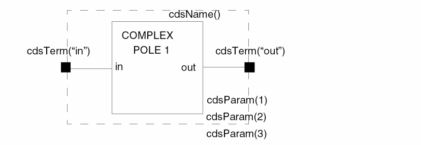
In previous chapters, you used the Edit CDF form on the complexPole1 component to look at the Component Parameter and Simulation Information sections of the CDF description. Now you look at the Interpreted Labels information in the complex pole CDF description and see how it affects the display of the component’s symbol.
The following figure shows the Interpreted Labels tab of the Edit CDF form for complexPole1.
-
Look at the complexPole1 symbol in the Symbol Editor. (Open the complexPole1 design, specifying the symbol cellview.)
You see a generic version of the component, with no values displayed.
- Open an empty schematic editor window by creating a new design.
-
Use the Add Instance command to add a complexPole1 component to the schematic.
Its symbol looks like this:
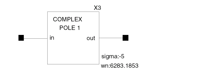
The two default parameter values from the Component Parameters tab and the instance name are set to be displayed (with the Use cdsParam to display setting in the Parameters(cdsParam) tab and the Use cdsName to display setting in the Cell/Inst Name(cdsName) tab). However, the Use cdsTerm to display setting in the Terminals(cdsTerm) tab is set to Net Name, and the component is by itself, not connected to any nets. There are no net names to display on the terminals (in and out).
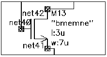
NFET Example
The NFET symbol in the following figure shows the effect of setting Use cdsParam to display setting in the Parameters(cdsParam) tab to Instance/CDF Parameters with the model, l and w parameters. Three parameters, model, l, and w, are displayed. There is no parameter name displayed with bmemne (the model name) because the Show Value Only check box next to the model parameter is selected in the Parameters(cdsParam) tab.
The default values from the CDF description are displayed for the l and w parameters, as shown by the format of parameter name : value (l:3u and w:7u). In addition, the Use cdsTerm to display setting in the Terminals(cdsTerm) tab is set to Net Name and the Use cdsName to display setting in the Cell/Inst Name(cdsName) tab is set to Instance Name. Unlike the complex pole example, this transistor is connected to nets in a schematic, so the net and instance names are all displayed.
Try changing the fields to different settings and then view the results.
You can use labels in any view. For example, you can set up a layout with labels so that you can
instance and parameter information when you place an instance:
This can be especially useful when you build the ivpcell used in layout extraction. In this way, when you look at the extracted layout, you see the instance found and the parameters measured.
Return to top