12
Checking Electrical Rules (ERC)
Introduction
The Electrical Rules Check (ERC) program verifies the structure and integrity of a network without doing a full Layout Versus Schematic (LVS) comparison. Because its primary processing is based on the circuit netlist, you can use it on extracted views or schematics.
ERC does not provide the accuracy that the LVS does, but it does provide valuable information that helps you to remove many errors from your circuit prior to LVS checking.
- Generates a netlist for the circuit
- Verifies the circuit using the verification rules in your ERC rules file and the run options you specify in the ERC form when you select the ERC command from the Verify menu
- Verifies device parameters using an internal feature that combines parameters during series and parallel reduction
- Outputs error files that can be used to view and probe errors
- Displays and explains the errors it found
The ERC program is controlled by the system simulation environment (se). The simulation environment is normally set up by your system administrator. See
You can run ERC using the ERC command from the Verify menu or using the ivERC SKILL command.
You control ERC processing by entering verification rules in the ERC rules file and by choosing options in the ERC form. The verification rules commands define the type of verification checks you want to run. The form options define requirements for a specific run.
Prerequisites
- You must define ERC verification rules in a text file.
-
You must extract a network so that ERC can generate the netlist it needs.
To create the layout network, run an extraction on the layout using the Extract command from the Verify menu to get an extracted view.
To create the schematic network, run a check on the schematic using Edit – Check – Current Cellview. - You must initiate ERC from a window containing either a schematic cellview or an extracted layout cellview.
Program Functionality
These sections describe the verification rules commands available in ERC and their overall function.
Defining External Connections
The following commands define the circuit connections. Many other commands use this information. In some cases, the circuit connection definition is essential to the functioning of the command and in other cases, it eliminates spurious errors. For example, the pull-up and pull-down commands cannot function without power and ground definition. The commands can produce spurious errors if inputs are not defined. The commands are as follows:
setPower
setGround
setInput
setOutput
Tracing Paths
The following commands define the flow characteristics of devices. The pull-up and pull-down commands use these characteristics to determine how the tracing of the circuit proceeds through devices. For example, a MOS transistor has its source and drain defined in a twoWayPath command so that the pull-up and pull-down processing can trace every net through the source and drain to power and ground.
By selectively defining which nets are power and ground, and what the device paths are, you can use these commands for generalized path tracing.
oneWayPath
twoWayPath
Pull-Up and Pull-Down Tracing
Pull-up and pull-down tracing starts at every net and goes through each device path looking for power and ground. By selectively defining which nets are power and ground, you can use these commands for generalized path tracing instead of conventional pull-up and pull-down tracing.
checkPullUp
checkPullDown
checkPullUpAndDown
Counting Connectivity
The following commands select devices and nets based on the number of connections to them. The first commands check for nonfunctional devices and nets because they have one or no connections. The other commands look for specific counts of connections.
Because input and output nets connect externally to the circuit, those nets are treated as if they have at least one connection to a device terminal.
checkFloatingDevices
checkFloatingNets
checkOneNetDevices
checkOneTerminalNets
checkDeviceNetCount
checkFanOut
Checking Connectivity
The following commands select devices by their direct connections, or lack of direct connections, to specific nets.
checkConnected
checkNotConnected
Forming Gates
The following commands let you combine MOS transistors into gates and test the circuit result for feedback loops. In addition, a simple gate-level netlist is created. The program recognizes a preset number of gate configurations. Any devices not forming gates can be seen as gate errors.
During the formation of gates, the program can consolidate individual device parameters into gate parameters using procedures you define.
reduceDevice
displayGateErrors
displayFeedBackLoops
Testing Properties
The following commands let you test the parameters of individual devices and gates:
testDeviceProperty
testGateProperty
Program Output
All the errors found by the ERC check are placed in error output files, which the program uses to display and explain errors.
The output files are stored in subdirectories of the run directory. When you use the ERC form, you must specify the run directory where you want to put your results. The program then creates the run directory (if one does not already exist). When you run an ERC check, the resulting error output files are put in the appropriate directories.
The outputs from ERC fit into these categories:
- The probe.err error file that you can read to find the name of the net or device causing an error
- Working and information files that you can display by using menu commands
- Control and cross-reference files that you cannot access
- A copy of the rules file under the name divaERC.rul
probe.err Files
This text file contains the error output of the ERC program. It is stored in the layout or schematic subdirectories of the run directory. Diva highlights the nets and devices referenced in this file when you select Display Errors in the ERC form.
You can also display the contents of this file by selecting Show Run Info in the ERC form.
Working and Information Files
The following files contain information that you can display using the Show Run Info form, which you access from the ERC form.
Text file containing the netlist of the circuit. You can view this file by selecting the Netlist option in the Show Run Info form.
Text file containing all messages and warnings output from the program. You can view this file by selecting the Output option in the Show Run Info form.
Text file containing information pertaining to the program execution and its environment. It also includes summary information of the results of the operations you requested. You can view it by selecting the Log option in the Show Run Info form.
ERC Functions
To make its checking process easier, ERC lets you simplify your circuit by reducing devices and forming gates. It also combines the parameters of the reduced devices so that you can compare them. This section gives a detailed explanation of network reduction and parameter consolidation.
Reducing Networks
ERC gives you three options for reducing (simplifying) your network:
-
Series
Reduces all series devices of the same type to a single device. It takes into account the polarity of devices where this is appropriate. Consolidates parameters if requested. -
Parallel
Reduces all parallel devices of the same type to a single device. It considers the polarity of devices where this is appropriate. Consolidates parameters if requested. -
MOS
Recognizes and builds logic gates from groups of MOS transistors. It builds the logic by iteratively combining transistors in logical AND and OR configurations, followed by the combining of pull-up and pull-down logic functions. Consolidates parameters if requested. Any devices not consolidated into logic gates are left as discrete devices.
Reducing Series Devices
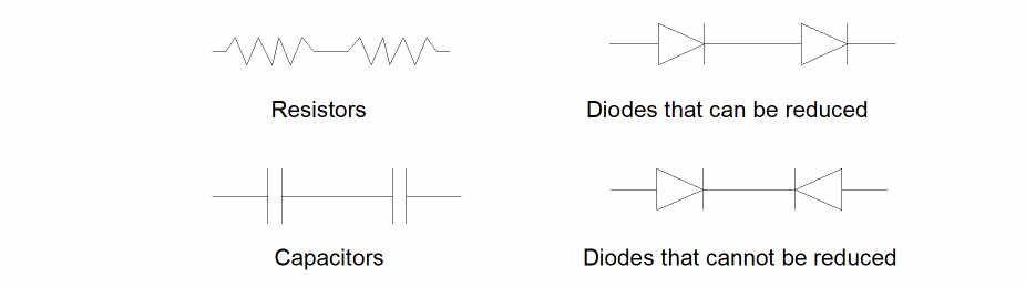
You can combine devices of the same type that are connected in series by “series reduction.”
To be combined in series, the device type must have two terminals. Two devices must be connected by a single net. That net must not be connected to any other device and must connect one of the terminals from each of the devices being combined. If the two terminals of the device type are permutable, it doesn’t matter which two are connected. If the two terminals of the device type are not permutable, then the connection must be between unlike terminals.
The following figure illustrates typical series configurations.
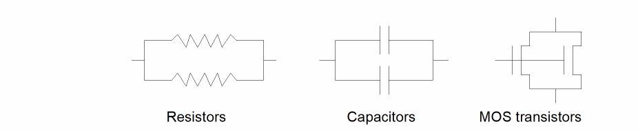
Reducing Parallel Devices
You can combine devices of the same type that are connected in parallel by using “parallel reduction.”
You can connect devices in parallel regardless of the number of terminals they have. However, you must connect each terminal of each device directly to a terminal of the same type on another device of the same type. Terminals are of the same type if they are defined as permutable. The nets connecting the terminals can have other connections.
The following figure illustrates typical parallel configurations.
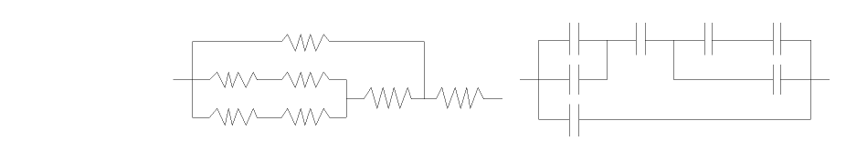
If you use for one device permuteDevice commands specifying both series and parallel options, both options are applied iteratively until no more reduction is possible.
The following figure illustrates complex configurations that reduce to single devices when both series and parallel options are applied.
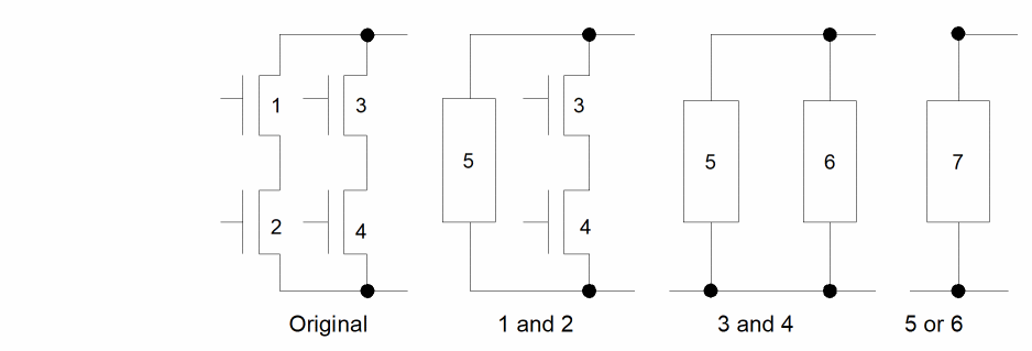
Reducing MOS Devices
You can group together MOS transistors if they are of the same type and form a logical function. Such groups form the logic section of NMOS gates and the load and logic sections of CMOS gates.
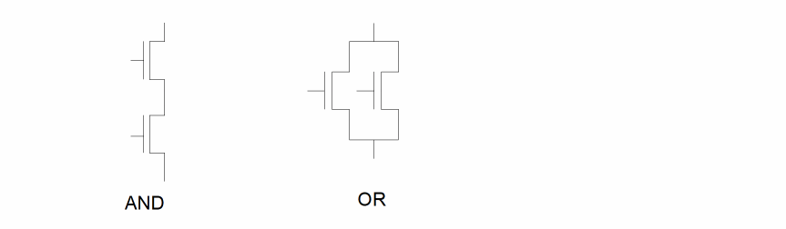
In normal MOS layout, the gate structures do not have to match the schematic exactly for the circuit to function. Most gates have alternative forms. Take for example a three-input AND structure as shown in this figure.
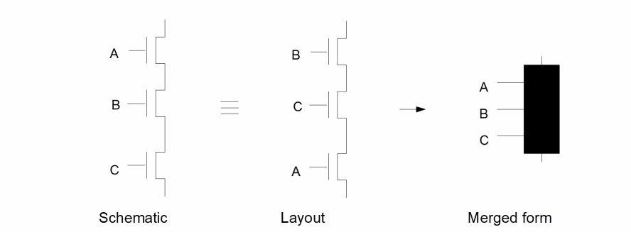
If the schematic has the original transistors in the order A-B-C and the layout has them in the order B-C-A, the comparison of the circuits fails. The MOS grouping process combines the three separate transistors into a single device with three permutable terminals. With this single device, the terminal ordering doesn’t matter and the layout device matches the schematic device, which causes the original devices to match.
Diva groups MOS devices using device pairs in exactly the same way as in series and parallel reduction. In this case, however, there are two separate criteria controlling the grouping.
The first grouping criteria is an AND configuration as used in the previous example. If a transistor source/drain connects to the source/drain of another transistor of the same type, and that connecting net has no other connections, then the devices are grouped.
The second grouping criteria is an OR configuration. In this configuration, two transistors have a common net for both their source and drain.
The following figure illustrates AND and OR configurations.
The following figures illustrate how the logic of a complex gate is permutable and how the grouped result is the same for either.
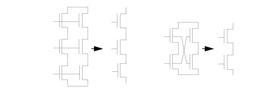
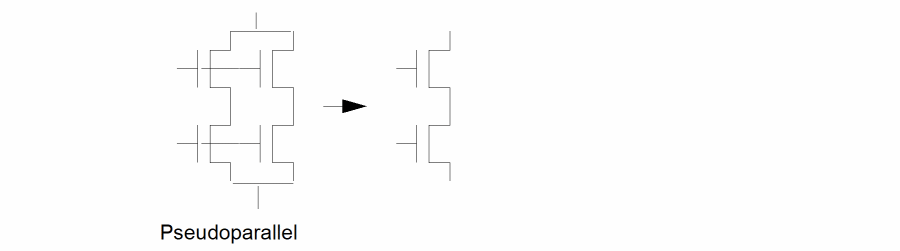
During the MOS grouping, certain transistor configurations can be encountered that function electrically as if they are in parallel but that do not conform to the conventional concepts of parallel. These transistors are merged together as if they are parallel. They are referred to as pseudoparallel.
The following figure illustrates two of these configurations.
If you specify both series and parallel consolidation, Diva applies these two functions iteratively until no further reduction is possible. If you request MOS reduction, series and parallel reduction for those devices is implied.
Defining Device Pin Permutability
To correctly perform reduction, ERC needs to know the permutability of device terminals (whether they can be interchanged). For example, source and drains of an MOS transistor are permutable. This means they can be interchanged. This concept extends to larger, more complex devices, where the permutations can be more complex and less obvious.
You define the pins of a device as permutable or fixed by attaching a property to its cell. This property defines whether the pin can be reduced or whether its relationship must stay unchanged. The system netlister adds this information to the netlist so the ERC program can use it.
permuteRule
The recognized keywords in the property are p for permutable and f for fixed. An example of the property contents is
( p 1 2 )
This specifies that terminals 1 and 2 on this device are interchangeable.
This is a more complex example.
(p ( p 1 2 ) ( p 3 4 ) )
This specifies that terminals 1 and 2 are permutable, as are terminals 3 and 4. Also, the pair of 1 and 2 are permutable with the pair of 3 and 4.
The following figure illustrates more complex permutability.
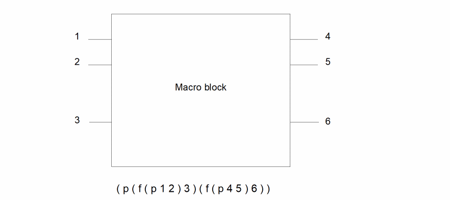
This specifies that terminals 1 and 2 are interchangeable but fixed relative to 3. Terminals 4 and 5 are interchangeable but fixed relative to 6. Group 1, 2, 3 is permutable with group 4, 5, 6.
Consolidating and Testing Parameters
When you reduce a group of devices to one device or form a gate, you must also combine the parameters (properties) of the devices involved. For ERC to correctly consolidate the parameters, you must tell it what to do by supplying a parameter consolidation SKILL routine.
You also can test the parameters (such as width, length, or area) of the reduced devices and gates to ensure they meet your design standards. For ERC to correctly test these parameters, you must supply a test SKILL routine.
Combining Series/Parallel Parameters
You can use the reduceDevice command to reduce groups of serial and parallel devices of the same type to a single device. Each time you reduce a pair of devices to a single device, the device parameters must be consolidated into a single parameter. This results in a final correct parameter for each device generated for a group of series/parallel devices.
How this consolidation is done depends upon the technology, the application, the type of reduction, the device type, and any other factors you want to introduce. The only way the program can correctly consolidate parameters is for you to tell it what you want it to do. You do this by supplying a routine, written in SKILL, for each type of reduction and device type you require.
The SKILL routine you write must accept as input two lists of parameters, one list for each device. Each list is in the netlist and contains all the parameters for that device. The routine determines if the parameters you want consolidated are actually present in the list and then does the necessary processing to combine them. Diva passes the resulting new list of parameters back to the ERC program.
The result can be the resultant parameters only, or a combination of the new ones plus uncombined originals. For example, if ERC is consolidating two resistors in series, it passes the SKILL routine the string of parameters attached to each of them. The SKILL routine, in this case, selects the R parameter and sets Rnew = R1 + R2. It then returns Rnew as the new value of R to be attached to the consolidated device.
You must place the SKILL routines that perform parameter reduction before any of the other ERC commands in the ercRules( ) section of the verification rules file.
Series/Parallel Example
In the following example, the comments clarify the application and do not describe the basic SKILL structure or syntax. For information on SKILL, refer to the
The contents of the procedures (routines) can be as complex as you want, and you can use any of the parameters found in the property strings associated with the devices. For example, you can calculate the width and length resulting from combining two transistors by using their original widths and lengths plus parameters such as bend counts, as well as any constants or factors.
The example shows procedure for combining parameters during a parallel reduction. The numbers at the beginning of the line are for reference in the comments below only and do not appear in the final code.
1    procedure( parallelMOS( m1, m2 )
2     prog( ( mt )
3      mt = ncons( nil )
4      if( ( m1->L && m2->L )
5       mt->L = ( m1->L + m2->L ) / 2.0
6      )
7      if( ( m1->W && m2->W )
8       mt->W = m1->W + m2->W
9      )
10      return( mt )
11         )
12    )
Defines the procedure name parallelMOS for a parameter consolidation routine in a reduceDevice statement. It also defines two arguments, m1 and m2, which the routine expects to receive. These two arguments are each lists of all the parameter properties on the devices being combined.
Sets up a local variable as a list (initially a null) that contains your resulting parameter list for the combined device.
Checks to see if both the m1 and m2 lists contain a reference to a parameter called L. If they do, line 5 calculates a resulting value as (L1+L2)/2 and stores it in the new list mt with the parameter name of L.
Checks to see if both the m1 and m2 lists contain a reference to a parameter called W. If they do, line 8 calculates a resulting value as W1+W2 and stores it in the new list mt with the parameter name of “W.”
Returns the resulting list mt back to calling program, where it is associated with the combined device.
Combining MOS Parameters
During generation of the gate-level netlist, two forms of reduction take place: AND and OR. This serves to combine device parameters to form pull-up and pull-down parameters. All devices of the same type and previously reduced structures forming an AND logic configuration are combined into higher level structures. The same is true for the OR configuration. By iterating these processes, the pull-up and pull-down portions of a gate can be reduced to single structures. Later these are combined to form the complete gate.
The following figure illustrates the logic of the AND/OR invert gate.
The figure shows the steps for converting the device-level logic into the gate pull-down structure. At each step, ERC reduces two components configured in either an AND or OR configuration to one. At each reduction, the appropriate routine combines the parameters of the two components into one set of parameters. The form of this combination depends on the routine you provide. If width and length are being combined, you might want to calculate an overall average. For beta ratios, you might select the worst- or best-case combination.
MOS Example
The following example illustrates both orMOS and andMOS routines for combining parameters.
The numbers at the beginning of the line are for reference in the comments below only and do not appear in the final code.
1     procedure( orMOS( m1, m2 )
2      prog( ( mt )
3       mt = ncons( nil )
4          if( ( m1->l && m2->l && m1->w && m2->w )
5       if( ((float( m1->w ) / float( m1->l )) >
       (float( m2->w ) / float( m2->l )))
       then
6          ( mt->w = m1->w )
7         ( mt->l = m1->l )
8       else
9         ( mt->w = m2->w )
10             ( mt->l = m2->l )
11           )
12      )
13          return( mt )
14     )
15    )
16     procedure( andMOS( m1, m2 )
17      prog( ( mt )
18          mt = ncons( nil )
19          if( ( m1->l && m2->l && m1->w && m2->w ) then
20            ( mt->w = ( float( m1->w ) + float( m2->w ))
             / 2.0)
21            ( mt->l = m1->l + m2->l )
22          )
23          return( mt )
24      )
25     )
The basic structure is the same as the previous series/parallel example. In the first procedure, orMOS (line 1), the routine checks for parameters w and l in both lists (line 4). If all exist, it checks the w/l ratio of one to the w/l of the other (line 5). The returned list (line 13) has its parameters set to those of the input list having the highest ratio. The concept here is that the final structure contains the parameters for the path (one or the other) that has the highest w/l ratio.
In the second procedure, andMOS (line 16), after checking the existence of all parameters (line 19), the routine sets the resultant w to the average of the two input “w” values (line 20), and the resultant l to the sum of the input l values (line 21). This simulates a structure that has one device in series (AND) with the other.
Combining Gate Parameters
When you combine gate parameters, the order of the input parameters is critical. The first input is always the load structure (pull-up) parameter list, and the second is always the logic structure (pull-down) parameter list.
The other consolidations normally create a parameter list containing exactly the same parameter names as their input. For gate parameter consolidation, however, you can create a completely different parameter list from the input.
Gate Example
This example follows the structure of those given previously, but creates the parameter betaRatio from the input w and l parameters.
1     procedure( gateMOS( m1, m2 )
2      prog( ( mt )
3       mt = ncons( nil )
4       if( ( m1->l && m2->l && m1->w && m2->w )
       then
5      mt->betaRatio = ( float(m1->w) / float(m1->l ) /
             ( float(m2->w) / float(m2->l ) ))
6      )
7      return( mt )
8     )
9    )
After testing for the existence of the required parameters in the pull-up and pull-down inputs (line 4), the routine calculates a new parameter, called betaRatio, from the ratio of the pull-up (input 1) w/l over the pull-down (input 2) w/l (line 5).
Testing Gate and Device Properties
The testing procedures are simpler than the reduction consolidation procedures in that they only have to process the parameters of a single device or gate; they do not have to generate a parameter list.
For each device whose type is specified in a testDeviceProperty or testGateProperty command, the SKILL routine you specify uses a single argument, which is the parameter list of the device. If the parameter list does not exist, your routine can either treat this as an error condition or not. Inside the routine you can do whatever processing you wish on any or all parameters in the list. You can test their values, combinations of values, or the existence of the parameters.
By testing, you can decide whether the parameters are acceptable or not. If the parameters fail your test, you must return t (for true), or a text string which is appended to the error message associated with that device. If the parameters pass your tests, you must return nil. The error text string automatically contains the relevant information of the device being tested, so the appended message can best be used to define the value against which the test failed.
The following example illustrates a simple test in which the parameters w and l are tested against a predefined ratio.
1    procedure( testMOS( m1 )
2     prog( ( )
3      if( ( m1->L && m1->W ) then
4       if( ( m1->W / m1->L ) != 3
5        return( “Wanted 3.” )
6       )
7      else return ( t )
8      )
9      return( nil )
10     )
11    )
Defines the procedure name testMOS, which is the name used for the procedure in the testDeviceProperty command. It also defines the single argument m1, which is a list of parameter properties. This list contains all the properties available on the device being tested.
Checks to see if the parameter list contains both L and W before continuing. If it does not, line 7 returns the value t (TRUE). The error message associated with this return automatically tells you if no parameter list exists. If you want to be more precise and specify that a particular parameter does not exist, then you must define a separate if test for each parameter name and provide a separate return text for each case.
Tests the ratio of W divided by L against the constant 3.
If the comparison fails, line 5 returns the text string “Wanted 3.” If the comparison succeeds, line 9 returns the value nil (FALSE).
The following example illustrates a simple gate property test.
1     procedure( testGate( m1 )
2      prog( ( )
3          if( ( m1->betaRatio )
4       if( m1->betaRatio > 1.3
5         return( t )
6           )
7          )
8      return( nil )
9      )
10     )
In this example, line 3 checks for the existence of the parameter betaRatio. Line 4 checks the parameter against the constant 1.3. If it is greater, an error is generated by returning t in line 5; otherwise, it is accepted by returning nil in line 8.
ERC Commands
This section describes the syntax for the commands used to define circuit connections and trace paths.
oneWayPath
oneWayPath( device terminal1 terminal2 )
Description
Specifies that during path tracing for pull-up and pull-down detection, this device is to be traced only from the net connected to terminal1 to the net connected to terminal2.
Fields
Name of the device to which this path definition applies. The name is a text string enclosed in quotation marks.
Device terminal name from which the path tracing can start. The name is a text string enclosed in quotation marks.
The device terminal name to which the path tracing goes. The name is a text string enclosed in quotation marks.
Example
The following example illustrates a diode in which the path tracing can go from anode to cathode but not from cathode to anode:
oneWayPath( "diode" "anode" "cathode" )
setGround
setGround( netName ...)
Description
Defines a list of nets that represent the ground connections to the circuit. These nets are used in the pull-down path tracing and are required for the recognition of gates during reduceDevice command processing.
Fields
Name of a net that represents a ground connection to the circuit. You can define any number of nets. Each net is a character string enclosed in quotation marks.
Example
The following example declares VSS and gnd! as ground supplies for the ERC and device reduction programs:
setGround( "VSS" "gnd!" )
setInput
setInput( netName ...)
Description
Defines a list of nets that represent the input connections to the circuit. These nets are used to eliminate false errors in the pull-up and pull-down path tracing. In addition, they are used to count single connections when looking for nets and devices that have one or zero connections.
Fields
The name of a net that represents an input connection to the circuit. You can define any number of nets. Each net is a character string enclosed in quotation marks.
Example
The following example declares all specified net names as input nets:
setInput( "ph1" "ph2" "clock" "in1" "in2" )
setOutput
setOutput( netName ...)
Description
Defines a list of nets that represent the output connections to the circuit.
You use these nets to count a single connection when looking for nets and devices that have one or zero connections.
Fields
Name of a net that represents an output connection to the circuit. You can define any number of nets. Each net is a character string enclosed in quotation marks.
Example
The following example declares all specified net names as output nets:
setOutput( "out1" "out2" "trigger" "clock" )
setPower
setPower( netName ...)
Description
Defines a list of nets that represent the power connections to the circuit. These nets are used in the pull-up path tracing and are required for the recognition of gates during reduceDevice command processing.
Fields
Name of a net that represents a power connection to the circuit. You can define any number of nets. Each net is a character string enclosed in quotation marks.
Example
The following example declares VDD and vdd! as power supplies for the ERC and device reduction programs.
setPower( "VDD" "vdd!" )
twoWayPath
twoWayPath( device terminal1 terminal2 )
Description
Specifies that during path tracing for pull-up and pull-down detection, this device can be traced from the net connected to terminal1 to the net connected to terminal2 and in the opposite direction from the net connected to terminal2 to the net connected to terminal1.
Fields
Name of the device to which this path definition applies. The name is a text string enclosed in quotation marks.
Name of the device terminal name at which the path tracing can start or end when passing through the device. The name is a text string enclosed in quotation marks.
Name of the device terminal where the path tracing goes when passing through the device. The name is a text string enclosed in quotation marks.
Examples
The following examples illustrate typical devices that have two-way trace paths:
twoWayPath( "nfet" "S" "D" )
twoWayPath( "resistor" "PLUS" "MINUS" )
Tracing and Connectivity Commands
This section describes the syntax for the commands used to trace pull-ups and pull-downs and check connectivity.
checkConnected
checkConnected( device terminal net )
Description
Finds devices based on the connection of specific device terminals to defined nets. ERC selects each device of the type specified if any of the specified terminals connect to any of the specified nets.
All selected devices are referenced in the error file with a message. You can display these devices by selecting Display Errors in the ERC form.
Fields
Name of a device, consisting of a text string enclosed in quotation marks. Only connections to this device are considered.
Name of a device terminal, consisting of a text string enclosed in quotation marks or a list of device terminals surrounded by parentheses. The terminals must belong to the device previously defined. Only connections to these device terminals are considered.
A single net name enclosed in quotation marks or a list of net names surrounded by parentheses. If any of the device terminals connect to any of these nets, the device is selected.
Examples
The following example flags all nfet devices whose gates are connected to vdd.
checkConnected( "nfet" "G" "vdd")
The following example flags all nfet devices whose sources or drains are connected to vdd or VDD.
checkConnected( "nfet" ( "S" "D") ("vdd" "VDD") )
The following example flags all pfet devices whose source, drain, or gate terminals are connected to vss or gnd.
checkConnected( "pfet" ( "S" "D" "G") ( "vss" "gnd") )
checkDeviceNetCount
checkDeviceNetCount( device terminal limit )
Description
Finds devices based on the number of distinct nets connected to them through specific terminals. The limit argument defines the number of nets. If the number of nets meets these limits, the device is selected.
A single net connected to more than one of the terminals of a device is counted only once. A net is counted only if it connects to more than one device terminal, or if it connects a device terminal to an I/O of the circuit. If a terminal of a device is floating (it does not connect to another device terminal or an I/O of the circuit), it is considered unconnected.
All selected devices are referenced in the error file with a message. To display these devices, select Display Errors in the ERC form.
Fields
Name of the device to which this command applies. The name is a text string enclosed in quotation marks.
Name of a device terminal. The name is a text string enclosed in quotation marks. The terminal must belong to the device previously defined. Only nets connected to this device terminal are counted. This can also be a list of terminal names surrounded by parentheses.
Limit specification. The options are as follows:
lower_limit operator keyword operator upper_limit
keyword operator upper_limit
keyword operator lower_limit
You can use the following keywords:
keep
ignore
You can use the following operators:
<
<=
>
>=
==
You can use the following limit specifications:
keep < 3
2 < ignore < 5
ignore > 5
keep == 3
Examples
checkDeviceNetCount( "npn" "e" keep < 3 )
checkDeviceNetCount( "npn" ( "e" "c" ) 2 < ignore < 5 )
checkDeviceNetCount( "npn" ( "e" "b" "c" ) keep > 5 )
checkDeviceNetCount( "nfet" ( "S" "D" ) keep == 1 )
checkFanOut
checkFanOut( device terminal limit [usage net] )
Description
Finds nets based on the number of device terminals of a specific type connected to them. You define the number of terminals with the limit definition in the command. If the count of terminals meets these limits, the net is selected.
You can extend the command to specify exactly which nets are to be checked or which nets are not to be checked.
All selected nets are referenced in the error file with a message. You can display these nets by selecting Display Errors in the ERC form.
Fields
Name of a device, consisting of a text string enclosed in quotation marks. Only connections to this device are counted for any net.
Name of a device terminal, consisting of a text string enclosed in quotation marks. The terminal must belong to the device previously defined. Only connections to this device terminal are counted for any net. This can also be a list of terminal names surrounded by one set of parentheses.
Limit specification. The options are as follows:
lower_limit operator keyword operator upper_limit
keyword operator upper_limit
keyword operator1 lower_limit
You can use the following keywords:
keep
ignore
You can use the following operators:
<
<=
>
>=
==
You can use the following limit specifications:
keep < 10
2 < ignore < 8
ignore > 5
keep == 3
Optional keyword that precedes a net name or list of net names. The options are as follows:
for
except
The for keyword precedes a list of nets that are to be checked. The except keyword precedes a list of nets that are not to be checked. Without the usage keyword, all nets are checked.
A single net name enclosed in quotation marks or a group of net names surrounded by parentheses. This list is applied according to the preceding keyword for or except.
Examples
The following example flags all nets that connect to more than three gate terminals (terminals named G) of n channels (devices whose model name is nfet).
checkFanOut( "nfet" "G" keep > 3 )
The following example flags only nets named ph1 and ph2 that connect to more than ten gates of nfet devices.
checkFanOut( "nfet" "G" keep > 10 for ("ph1" "ph2") )
The following example flags all nets that connect to more than one pfet source or drain.
checkFanOut( "pfet" ( "S" "D") keep > 1 )
The following example flags all nets except vdd and gnd that connect to more than five gates of nfet devices.
checkFanOut( "nfet" "G" keep > 5 except ("vdd" "gnd") )
The following example flags all nets, except a1, a2, and a3, that connect to more than two but less than five e or c terminals on npn transistors.
checkFanOut( "npn" ("e" "c") 2 < ignore < 5
except ("a1" "a2" "a3") )
checkFloatingDevices
checkFloatingDevices( )
Description
Finds all devices that have no connections to the remainder of the circuit. Although each of the device’s terminals connects to a net, none of those nets connect to terminals of other devices.
All floating devices are referenced in the error file with a message. You can display floating devices by selecting Display Errors in the ERC form.
Example
checkFloatingDevices( )
checkFloatingNets
checkFloatingNets( )
Description
Finds all nets with no connections to device terminals in the circuit. A reference to a net in a setInput or setOutput command is considered a single connection to the net.
All floating nets are referenced in the error file with a message. You can display floating nets by selecting Display Errors in the ERC form.
Example
checkFloatingNets( )
checkNotConnected
checkNotConnected( device terminal net )
Description
Finds devices based on the absence of connection of specific device terminals to defined nets. If none of the specified terminals connect to any of the specified nets, ERC selects each device of the type specified.
All selected devices are referenced in the error file with a message. You can display these devices by selecting Display Errors in the ERC form.
Fields
Name of a device, consisting of a text string enclosed in quotation marks. Only connections to this device are considered.
Name of a device terminal, consisting of a text string enclosed in quotation marks or a group of device terminals surrounded by parentheses.
The terminals must belong to the device previously defined. Only connections to these device terminals are considered.
A single net name enclosed in quotation marks or a list of net names surrounded by parentheses. If none of the device terminals connect to any of these nets, the device is selected.
Examples
The following example flags all pfet devices whose source or drain terminals are not connected to vdd.
checkNotConnected( "pfet" ( "S" "D") "vdd" )
The following example flags all cap devices that have neither terminal connected to vdd or gnd.
checkNotConnected( "cap" ( "PLUS" "MINUS") ( "vdd" "gnd"))
checkOneNetDevices
checkOneNetDevices( )
Description
Finds all devices that have only one connection to the remainder of the circuit. Although each of the device’s terminals connects to a net, only one of those nets connects to a terminal of another device.
All single net devices are referenced in the error file with a message. You can display these nets by selecting Display Errors in the ERC form.
Example
checkOneNetDevices( )
checkOneTerminalNets
checkOneTerminalNets( )
Description
Finds all nets that have only one connection to a device terminal in the circuit. A reference to a net in a setInput or setOutput command is considered a single connection to the net.
All single terminal nets are referenced in the error file with a message. You can display these nets by selecting Display Errors in the ERC form.
Example
checkOneTerminalNets( )
checkPullDown
checkPullDown( )
Description
Starts a trace at every net in the circuit other than the power nets and determines whether that trace can reach the nets defined as ground. It traces through devices as defined by the oneWayPath and twoWayPath definitions. The command has no arguments.
If you use the usual definitions of ground, with the source and drain of MOS transistors defined in a twoWayPath definition, this command performs the conventional pull-down checking.
All nets that cannot be traced (pulled down) are referenced in the error file with a message. You can display these nets by selecting Display Errors in the ERC form.
Prerequisite
You must first define ground connections and device paths.
Example
The following example checks all nets, except those declared as inputs by setInput, for a path to a declared ground supply.
checkPullDown( )
checkPullUp
checkPullUp( )
Description
Starts a trace at every net in the circuit other than the ground nets and determines whether that trace can reach the nets defined as power. It traces through devices as defined by the oneWayPath and twoWayPath definitions. The command has no arguments.
If you use the usual definitions of power, with the source and drain of MOS transistors defined in a twoWayPath definition, this command performs conventional pull-up checking.
All nets that cannot be traced (pulled up) are referenced in the error file with a message. You can display these nets by selecting Display Errors in the ERC form.
Prerequisite
You must first define power connections and device paths.
Example
The following example checks all nets, except those declared as inputs by setInput, for a path to a declared power supply.
checkPullUp( )
checkPullUpAndDown
checkPullUpAndDown( )
Description
Starts a trace at every net in the circuit other than the power and ground nets and determines whether or not that trace can reach the nets defined as power and ground. It traces through devices as defined by the oneWayPath and twoWayPath definitions. The command has no arguments.
If you use usual definitions of power and ground, with the source and drain of MOS transistors defined in a twoWayPath definition, this command performs conventional pull-up and pull-down checking.
All nets that cannot be traced to power or to ground (pulled up or down) are referenced in the error file with a message. You can display these nets by selecting Display Errors in the ERC form.
Prerequisite
You must first define power connections and device paths.
Example
The following example checks all nets, except those declared as inputs by setInput, for a path to declared power and ground supplies.
checkPullUpAndDown( )
Gates and Parameters Commands
This section describes the syntax for the commands used to form gates and test parameters.
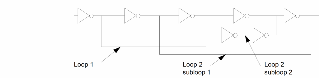
displayFeedBackLoops
displayFeedBackLoops( )
Description
Requests display of all loops in the circuit after the circuit has been reduced to the gate level using the reduceDevice command with the MOS keyword.
A loop is formed when the output of a gate can be traced, through inputs of other gates, back to the input of the original gate. ERC detects all loops, whether they are isolated, nested or crossing. Each loop is given a loop number and a subloop number. The subloop number is used when a single loop has multiple paths within it.
All nets forming loops are referenced in the error file with a message. You can display nets forming loops by selecting Display Errors in the ERC form.
Prerequisites
This command is applicable only after using a reduceDevice command with the MOS keyword.
The following figure illustrates the formation of loops and subloops.
Example
displayFeedBackLoops( )
displayGateErrors
displayGateErrors( )
Description
Requests display of all transistors that have failed to become part of a gate during device reduction initiated with the reduceDevice command with the MOS keyword.
If individual transistors do not form part of any of the recognized gates, they are left in the circuit and form part of the netlist. This command simplifies the isolation of those devices in cases where you assumed the devices formed gates. It is probable that gates have not been formed because the transistors are not correctly connected, or they form a gate type not recognized by the program.
All selected devices are referenced in the error file with a message. You can display these devices by selecting Display Errors in the ERC form.
Prerequisites
This command is applicable only after a reduceDevice command with the MOS keyword.
Example
displayGateErrors( )
reduceDevice
reduceDevice( type device [key] [spFunction] [andFunction orFunction])
Description
Requests that the circuit netlist be simplified (reduced) by combining series and parallel devices, creating logic gates from MOS transistors, or both.
During reduction, you can consolidate the original parameters defined as properties of the devices into new parameters by using SKILL functions you write. To create logic gates, you can define SKILL functions that calculate the gate-level parameters from the parameters of the load and logic portions of the gate.
If this command produces a reduced logic gate network, it writes out the network in text format in a form that can be directly used or translated for use by other programs.
Prerequisites
For full reduction, you must specify the permutability of device terminals in the device definitions in the netlist. To help this command create logic gates, use the setPower and setGround commands.
Fields
Defines the type of reduction to be performed. The options are as follows:
Merges devices of the same type connected in series into a single device. You can specify two-terminal or MOS devices. If the two device terminals are permutable, this command merges the devices regardless of the way they are connected. If the two terminals are not permutable, the command merges the devices only if unlike terminal types are connected.
Merges into one all the terminals of two devices of the same type that have common nets.
Creates logic gates out of groups of transistors by recognition of pairs of devices in AND and OR configurations. It can handle NMOS or CMOS technologies and is limited to creating gates of these types. These definitions show the terminal ordering of the resultant gate. The nand, nor, and complex gates are illustrated by single examples, but the full range of configurations is available.
inverterout in
nmos xfer gatedrain in source
cmos xfer gatedrain nin pin source
tristateout common nin pin
nand3out in1 in2 in3
nor3out in1 in2 in3
aoi321out in3a in3b in3c in2a in2b in1a
oai321out in3a in3b in3c in2a in2b in1a
For a MOS device to be reduced correctly, its terminal ordering in the netlist must conform to SPICE conventions of (S G D B), and in the device definition, it must have the correct source and drain permutation statement (p S D).
The keyword also triggers the creation of a netlist of the reduced circuit in the si.out file.
If you specify multiple reductions for the same device, all are applied iteratively. For example, if you request series and parallel reduction for resistors, both are applied to resistor networks, reducing them as far as possible.
The following figure illustrates normal series and parallel reduction.
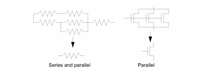
MOS reduction also implies parallel reduction plus reduction of pseudoparallel device combinations. In these cases, the devices are not truly connected in parallel but behave electrically as if they were.
The following figure illustrates pseudoparallel reduction during MOS reduction.
Name of a device consisting of a text string enclosed in quotation marks. The reduction process requested is applied to all devices of this type.
Used only during MOS reduction to specify that the type of the device in this command forms the logic part of the gate. In MOS, this is usually the nfet or its equivalent.
ERC recognizes gates in two parts. The load, which is normally the pull-up-to-power section, and the logic, which is normally the pull-down-to-ground section. During reduction, both sections are formed separately and then paired together with the output of the gate being the common net between the sections.
Used for series and parallel reduction. The key “netlist” is added to one of the reduceDevice commands. This keyword triggers the creation of a netlist of the reduced circuit in the si.out file. Used if the MOS reduction has not been applied but a netlist is wanted after series and parallel reduction only.
Optional name of a user-defined SKILL routine used to consolidate the device parameters (stored as properties on the devices) during series and parallel reduction.
This function is usually not used for MOS processing. The only exception is for pseudoparallel configurations.
The first function name encountered after the series or parallel keyword is assumed to be the sp_function.
Optional name of a user-defined SKILL routine used to consolidate the parameters (stored as properties on the devices) during MOS AND reduction.
This function cannot be used for series and parallel processing.
The first function name encountered after the MOS keyword is assumed to be the andFunction.
During MOS reduction, ERC combines devices by recognizing either an AND or an OR configuration. An AND configuration occurs when two devices of the same type have a common source/drain net with no other connection to that common net, and their other source/drain connections do not have common nets.
Optional name of a user-defined SKILL routine used to consolidate the parameters (stored as properties on the devices) during MOS OR reduction.
This function cannot be used for series and parallel processing. This is the second function after the MOS keyword.
The first function after the MOS keyword is considered to be the andFunction.
During MOS reduction, ERC combines devices by recognizing either an AND or an OR configuration. An OR configuration occurs when two devices of the same type have both their source and drain terminals connected to common nets, but not their gate terminals.
Examples
The following example reduces all resistor devices in series.
reduceDevice( series "resistor" )
The following example reduces all capacitor devices in parallel and calls a SKILL function to combine their parameters.
reduceDevice( parallel "capacitor" series_cap )
The following example reduces all nfet devices and references them as logic forming.
reduceDevice( MOS "nfet" logic )
The following example reduces all pfet devices and calls SKILL functions to consolidate parameters during reduction of AND and OR configurations.
reduceDevice( MOS "pfet" mos_and mos_or )
testDeviceProperty
testDeviceProperty( device testFunction )
Description
Lets you check the values of parameters stored on the devices as properties. ERC does this checking after doing any reduction. This means that for series and parallel reduction, ERC checks the parameters after they have been processed by the series and parallel consolidation functions.
For MOS reduction, the original parameters are maintained and checked on the original devices except in those cases where pseudoparallel reduction invoked the parallel consolidation function. ERC uses the AND and OR consolidation functions to create parameters for the resultant logic and load structures. This command does not check these parameters.
If you want to do checking prior to a reduction, you must make a separate run with the reduction commands omitted.
All devices failing the parameter test are referenced in the error file with a message. You can display these devices by selecting Display Errors in the ERC form.
Fields
Name of a device, consisting of a text string enclosed in quotation marks. ERC applies the requested parameter testing to all devices of this type.
Name of a user-defined SKILL routine used to perform the parameter testing. All devices of the specified type are processed when you specify this function.
Examples
The following example flags all nfet devices whose properties fail the user-defined SKILL evaluation.
testDeviceProperty( "nfet" testNfetParams )
The following example flags all resistor devices whose properties fail the user-defined SKILL evaluation.
testDeviceProperty( "resistor" resistor_WL_check )
testGateProperty
testGateProperty( createFunction [testFunction] )
Description
Provides data for the following processes:
- Defines the SKILL routine you used to create gate parameters after the gate level reduction has been performed. During gate level reduction, ERC creates load and logic sections, each gathering parameters from the AND and OR functions provided by the reduceDevice command. ERC passes these parameters to the SKILL routine, which then creates a set of parameters to be associated with the final gates created from the load and logic sections.
- Defines the SKILL routine to be used to test the values of the resultant gate parameters created by this routine.
All devices failing the parameter test are referenced in the error file with a message. You can display these devices by selecting Display Errors in the ERC form.
Fields
Name of a user-defined SKILL routine used to create the gate parameters.
Name of an optional user-defined SKILL routine used to perform the gate parameter testing. All gates are processed if you specify this routine.
Example
The following example calls a user-defined SKILL function (create_gate_prop) that creates gate-level parameters associated with the previously combined parameters that resulted from the device reduction. The second function (test_gate_prop) begins a user-defined check on the final parameters.
testGateProperty( create_gate_prop test_gate_prop )
Return to top