19.1 Overview
Most of the custom design level sign-off analysis is done in Virtuoso. The sign-off timing analysis of the flat top-level digital portion of the design can be done in Innovus. The mixed-signal functional simulation gives functional performance of the design at any stage of the design cycle.
Metal filling, optimization of metal density can be done in Innovus also which can be taken into account by QRC during extraction so that the timing effects due to metal fill can be addressed.
19.2 Virtuoso-Based ECO Flow
Use the following steps to run the Virtuoso-based ECO flow when the design changes are made at the top-level schematic:
- Large ECO: For large ECO changes, such as when the intent is to use only the existing floorplan, hard-block placement, reuse of power mesh, and so on, follow these steps:
- Run
verilog2oato import the new netlist in a new cellview. - Use the Load Physical View command in Virtuoso-XL Floorplanner to read the information from the old physical database selectively.
- Run
- Small ECO: To add/create a hierarchical ECO instance in Virtuoso in case of small ECOs:
- If the schematic is updated with minor changes to the net or instances, these changes can be tracked and data can be updated automatically in the Virtuoso-XL environment. You can use the Check Against Source command to track the changes and the Update Components and Nets command to update the layout as per the new schematic.
- You can also make the changes manually. To create a hierarchical instance, use the symbol ` which indicates a module hierarchy present in the design. For example, an instance with name M1`A1 implies that a module hierarchy present with the A1 module inside the module M1.
For the VDI flow for AoT designs, use the following steps when there are changes in the digital block netlist or the floorplan:
- Netlist has changes: The digital block is implemented but there is a new netlist for the block.
- If the netlist changes are large, use the
oaIn -filteroption to load in selective data like macro placement, power routing and power domains and pre-routes from the previously implemented cellview. To accomplish this, you need to initialize the new design in Innovus by invoking Innovus and using the new netlist to create a new cellview. You can then useoaIn -filterto selectively import physical objects from the older cellview, which was generated with the old Verilog netlist. For example, if you are interested in importing the block placement from the older cellview into the new cellview (the cellview created from the new Verilog netlist), use the following command:oaIn lib cell view -filter block_insts
Here,lib cell viewrefers to the old cellview. - If the netlist changes are small and you would like to use as much of the original cellview information, use the
ecoOaDesigncommand.
- If the netlist changes are large, use the
- Netlist remains same: The digital block is implemented but the block shape is changed, or pins are moved or their shapes changed.
- In this case, the Verilog netlist has not changed, so all that needs to be done is to import the new block boundary or pin location and update the previously implemented cellview. To do this, use the
oaIn -filtercommand to load in the new block shape or pin location as follows:oaIn lib cell view -filter boundary
- In this case, the Verilog netlist has not changed, so all that needs to be done is to import the new block boundary or pin location and update the previously implemented cellview. To do this, use the
Due to ECO changes, if a net gets modified, it needs re-routing using automatic router, use Innovus platform to route using NanoRoute.
19.3 Innovus-Based ECO Flow
19.3.1 Overview
The digital ECO flow is a methodology used to integrate the netlist modifications on a given design with minimal changes in the physical database to minimize the mask costs. This is only practical if the amount of change is minimal. Changes can also be achieved by modifying the interconnections of the existing netlist.
In the post-mask ECO flow, when a design has been taped out and requires logical changes, the corrections are performed by changing the logic in the Verilog file written from the old taped-out database. The pre-existing spare cells or the existing logic is used to accomplish the logical changes expected so that the poly/diffusion and lower layers are not changed, and only the metal and via layer masks are modified. To save mask cost, you can direct the tool to perform routing changes only within the specified layer range. The expected top-level flow steps are:
- Import the new Verilog file and pre-ECO design database into Innovus.
- Map new cells on spare cells, and map the deleted cells to be available as spare cells.
- Perform interactive ECOs such as
ecoSwapSpareCell, if needed. - Run
ecoRoutewith only a few layers getting changed.
To complete the ECO flow, you must provide the following inputs:
- New Verilog with logical modifications completed.
- Pre-ECO design database.
- List of spare cell modules to be used for ECO changes. If spare cells have been specified in previous Innovus sessions before saving the OpenAccess database, then they would be restored during
ecoOaDesigncommand.
- Permitted routing layers during
ecoRoute.
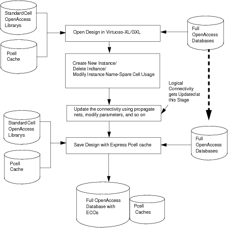
19.3.2 Pre-Mask ECO Flow Steps
The following figure depicts the pre-mask ECO flow that implements changes made through the netlist.
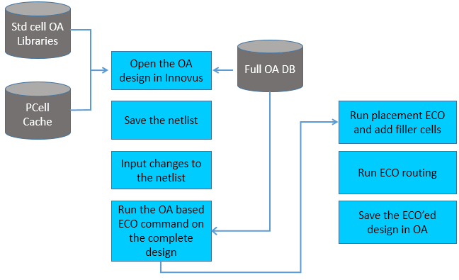
Follow these steps to run the pre-mask ECO flow:
- Run
restoreDesignto load pre-ECO library/cell/view. There is no need for a LEF technology library, as a common OpenAccess PDK can be used for the Innovus and Virtuoso environments, containing all technology information needed for the mixed signal implementation flow. - Run
saveNetlistto write out the old Verilog (with parameterized cells (PCells) in it, if they exist in the design). - Exit Innovus.
Note: If the old library/cell/view have no PCells, that is, it is a digital-only netlist, you can use the standalone utilityoa2verilogdirectly. The Innovus commandsrestoreDesignandsaveNetlistare required if PCells are present in the design. - Edit the Verilog netlist manually to implement the digital ECO changes.
- Start a new Innovus session. Run
setOaxMode -updateMode trueif there are analog objects like PCells, MPPs, fig-groups, in the old OpenAccess database. If this is a digital-only design without Virtuoso-specific objects or constraints, you do not need to usesetOaxMode -updateMode. - Run
ecoOaDesignto read the new ECO Verilog netlist, which copies all of the floorplanning, placement, routing and spare bit marking from the pre-ECO OpenAccess database except those not existing in the new Verilog file. Instances existing only in pre-ECO library/cell/view would not be added in the new Innovus database. - Run the
applyGlobalNetscommand to connect the global net connections for new instances. If your design is low-power-aware and you have a Common Power Format (CPF) file, use theread_power_intent -cpfandcommit_power_intentcommands to accomplish the above tasks. - Use
addTieHiLoif new tie-high or tie-low connections are needed.[ -cell "tieHighCellNametieLowCellName"][ -createHierPort {true|false}] - Run
ecoPlaceto place the new unplaced cells. According to requirements, thedeleteFiller-prefix FILLanddeleteNotchFillcommands may be required to delete the existing filler cells and notch fills before runningecoPlace. - Optionally, you can run the
selectInstandplaceInstancecommands to achieve fine-grain optimization in placement. -
Use the
addFiller -cell {...}command to add filler cells and then runecoRouteas required in the flow. After pereforming ECO routing, you need to take care of DRC, DFM and DFY changes as per requirement. For example, running theaddMetalFill,fillNotch, andtrimMetalFillcommands. - Run
saveDesign -cellviewto save the database in the new library/cell/view.
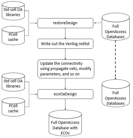
19.3.3 Post-Mask ECO Flow Steps
The following figure depicts the post-mask ECO flow.
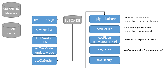
Follow these steps to run the post-mask ECO flow:
- Run
restoreDesignto load the pre-ECO library/cell/view. - Run
saveNetlistto write the pre-ECO Verilog file. - Exit the Innovus session.
Note: If the pre-ECO library/cell/view has no PCells, that is, it is a digital-only netlist, you can use the standalone utilityoa2verilogdirectly. The Innovus commandsrestoreDesignandsaveNetlistare required if PCells are present in the design. - Edit the Verilog netlist manually to implement the digital ECO changes.
- Start a new Innovus session. Use
setOaxMode -updateMode trueif there are analog objects like PCells, MPPs, fig-groups, in the pre-ECO OpenAccess database. If this is a digital-only design without full-custom objects or constraints, you do not need to usesetOaxMode -updateMode. - Run
ecoOaDesignwith the-postMaskoption to read the new ECO Verilog netlist, which copies all of the floorplanning, placement, routing and spare bit marking, from the pre-ECO OpenAccess database. - Run the
applyGlobalNetscommand to connect the global net connections for new instances. - Run
addTieHiLoif new tie-high or tie-low connections are needed:[ -cell "tieHighCellName tieLowCellName"][ -createHierPort {true|false}]-postMask
During this step in the post-mask mode, no new cells would be added. Only the already existing cells are used.
If you have Common Power Format (CPF) file, use theread_power_intent -cpfandcommit_power_intentcommands to accomplish the above tasks. - Run
ecoPlace-useSpareCells true, as required to map unplaced cells to spare cells. - Run
ecoSwapSpareCellif required in the flow, when auto-mapping was not according to your expectations. - Run
ecoRoute -modifyOnlyLayers N:M, as required in the flow. - Run
saveDesign -cellviewto save the database in the new library/cell/view.
19.3.4 Example Post-Mask ECO Scenarios
19.3.4.1 Pre-ECO Verilog
module spare ();
     // Internal wires
       wire LTIELO_1_NET;
       wire LTIELO_NET;
       TIELO LTIELO_1 (.Y(LTIELO_1_NET));
       TIELO LTIELO (.Y(LTIELO_NET));
       BUFX4 U6 (.A(LTIELO_NET));
       BUFX4 U7 (.A(LTIELO_1_NET));
endmodule

module TOP (Z, A);
    output Z;
    input A;
    // Internal wires
    wire net_pcell;

    inv_pcell I1 (.OUT(Z), .IN(net_pcell));
    BUFX8 U1 (.Y(net_pcell), .A(A));
    spare SU1 ();
endmodule
Note: In the pre-mask ECO flow, the newly added or modified instances will come as unplaced cells. The old cells (INVXL) are deleted from the database. The net physical geometries remain unchanged.
19.3.4.2 Post-ECO Verilog
module spare ();
   // Internal wires
     wire LTIELO_1_NET;
     wire LTIELO_NET;


   TIELO LTIELO_1 (.Y(LTIELO_1_NET));
   TIELO LTIELO (.Y(LTIELO_NET));
   BUFX4 U6 (.A(LTIELO_NET));
   BUFX4 U7 (.A(LTIELO_1_NET));
endmodule

module TOP (Z, A);
   output Z;
   input A;
   wire net_pcell, net1;
   inv_pcell I1 (.OUT(Z), .IN(net_pcell));
   BUFX4 ECO1 (.A(A), .Y(net1) );
   BUFX4 ECO2 (.A(net1), .Y(net_pcell) );
   BUFX8 U1 (.A(1'b0));
   spare SU1 ();
endmodule
Note: In the post-mask ECO flow, the newly added or modified instances (BUFX2) will come as unplaced cells. They can be mapped to a spare cell using the ecoPlace -useSpareCells parameter. The pre-ECO cell (INVXL) will remain in the database with placement information same as in the pre-ECO database. The physical geometries (nets) remain unchanged.
19.3.4.3 Example Command Sequence
ecoOaDesign designLib TOP layout -ecoVerilogFile eco.v -reportFile eco.rpt -postMask
applyGlobalNets
ecoPlace -useSpareCells true
addTieHiLo -postMask
ecoRoute -modifyOnlyLayers 1:2