10.1 Introduction to Trim Metal
10.1.1 The TRIMMETAL LAYER
The TRIMMETAL type masterslice layer is used to define trim metal layers. A trim metal layer is used along with metal layers manufactured with the self-aligned double patterning (SADP) technology, which is a form of double patterning technology (DPT). Several new LEF rules are applied on the trim metal layer. Place and route tools need to utilize this trim metal layer to achieve better QoR. defIn, defOut, and GDS streamOut need to support trim metal for RC extraction and physical verification.
The standard cell library may violate DRC rules, and you may require the router to patch on PIN and OBS to fix Minimum Area Rule (MAR) and/or enclosure violations as an example.
The first routing layer becomes M0 and is used for power rail connection.
10.1.2 General Requirements for N7, N5, and N3 Designs
N7/N5/N3 designs have the following general requirements:
- All objects, such as macro pins, block/IO pins, and PG stripes, in N7/N5/N3 designs should be on a track or grid for SADP or DPT layers.
- All objects must be rectangles and not rectilinear shapes.
- The place and route tools must follow the track color to place and route.
- The router can touch fixed objects, such as standard cell pin/obs and PG nets and vias.
- Cell libraries should be fully colored.
10.1.3 What Is Trim Metal?
Trim (cut) metal is used to shrink the end-to-end spacing, enclosure and Minimum Area Rule (MAR). The trim metal should always be sandwiched between two wire line ends along the preferred direction on TRIMMEDMETAL.
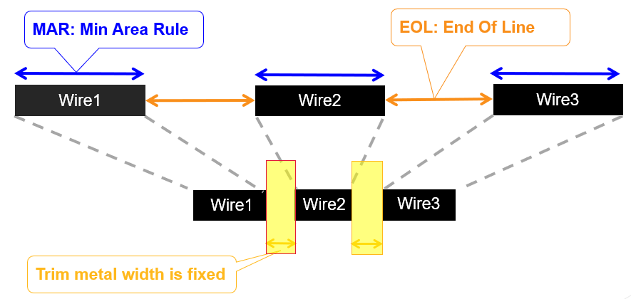
Consider the gap between wire line ends in the Automatic Place and Route (APR) view:

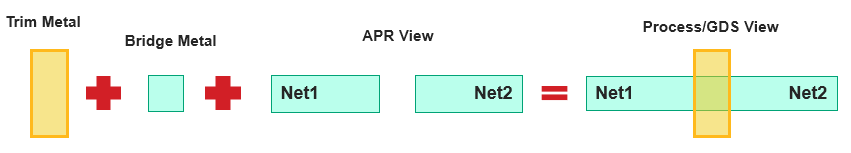
Metal needs to be generated to fill the gap between line ends in GDS, DEF, OpenAccess, and Full Geometry Checker (FGC). Additional metal shape, known as bridge metal, is generated during GDS streamOut. Trim metal and bridge metal is added to the APR view to get the Process/GDS view.
Routing trim metal supports:
-
Trim metal formation
-
Cell object extension for recommended locations
-
Trim metal spacing rule
-
Trim metal to metal spacing rule
-
Trim metal aware area rule
-
Trim metal aware enclosure rule
-
Trim metal for only one color on a metal
-
Fill up metal gap between wire line ends for checking other rules
10.2 Technology Requirements for Trim Metal Insertion
To enable trim metal insertion, you must define the trim metal layers in the functions section of the ASCII tech file.
layerRules( functions( ;( layer function [maskNumber] [attributes]) ;( ----- -------- ------------ ------------) ( M1 "metal" 104 ) (CM1A "trim" 105 ‘trims ((M1 m1ca_interconnect) )) (CM1B "trim" 106 ‘trims ((M1 m1ca_interconnect) )) );functions
You must also add the OpenAccess layer map (OALAYERMAP) property in the techParams section of the tech file. The OALAYERMAP property is used to define equivalence between LEF and OpenAccess layers and also between the geometries and shapes placed on the layers.
techParams( LEF58_OALAYERMAP "OALAYERMAP CM1A LAYER CM1 MASK 1 ; OALAYERMAP CM1B LAYER CM1 MASK 2;" );techParams
Finally, add the trimShape constraint in the ASCII tech file:
spacings( ( trimShape tx_layer 'exactWidth f_exactWidth ['maxLength f_maxLength] ['exceptSpacing f_spacing] ['exceptWidth f_width] ['extension f_extension ['metalEdge]] ['mask1 | 'mask2 | 'mask3 | 'mask4] ['insideLayers (tx_layer1 tx_layer2 ... tx_layerN) ['insidePurposes (t_purpose1 t_purpose2 ... t_purposeN)] | 'outsideLayers (tx_layer1 tx_layer2 ... tx_layerN) ['outsidePurposes (t_purpose1 t_purpose2 ... t_purposeN)] ] ['adjacentWidthExtension (f_adjWidth f_adjExtension)] ['keepoutRegion (f_offset1 f_offset2)] {"adjacentTrack" | "midTrack" | "extension"} ) ) ;spacings
The exceptSpacing and exceptWidth parameters trigger the interactive trim insertion.
A trim shape rule is created by using the TRIMSHAPE property in LEF:
PROPERTY LEF58_TRIMSHAPE "TRIMSHAPE EXTENSIONMODEL {ADJACENTTRACK | MIDTRACK | EXTENSION extension [METALEDGE]} EXACTWIDTH exactWidth [MAXLENGTH maxLength [MASK maskNum]] [EXCEPTSPACING spacing] [EXCEPTWIDTH width] [USEMETALMASK] ; " ;
The table below depicts the mapping of the TRIMSHAPE LEF property to ASCII:
| Tech LEF | Virtuoso (ASCII) |
|---|---|
|
|
trimShape |
|
|
|
|
|
|
|
|
|
|
|
|
|
|
|
|
|
|
10.3 Trim Metal Insertion Flow in Virtuoso
10.3.1 Trim Shape Rules
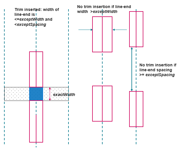
Trim shape rules can be used to specify that shapes on the TRIMMETAL layer should be formed based on the line-end wires on the metal layer that is trimmed. The rules for trim metal shape insertion are as follows:
- The trim shape must be rectangular and not rectilinear.
- The width of the trim shape measured in the preferred routing direction of the trimmed metal must be exactly equal to the
exactWidthvalue. - The trim shapes must always be formed at the line-end of wires on the trimmed metal.
- When the width of the line-end is greater than
exceptWidth,if specified, the trim shape is not formed. - When the line-end to line-end spacing is greater than or equal to
exceptSpacing, if specified, the shape is not formed.
10.3.2 Trim Shape Extension Models
Trim shapes can be extended using the following extension models:
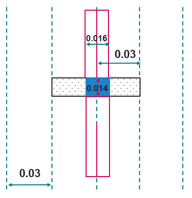
10.3.2.1 Extension from center
A trim shape can be extended from the center by the specified extension value in both directions. In the example below, the trim shape is extended from the center by 0.038 in both directions.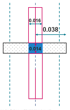
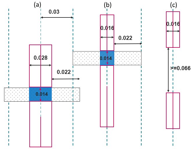
10.3.2.2 Extension from metal edge
If metalEdge is specified, the trim shape is extended from the metal edge in both the directions by the specified extension value. In the example below, the trim shape is extended from the metal edge by 0.022 in both directions.
Consider the extension model specification below from the ASCII tech file:
spacings(
trimShape "CM1A" 'exactWidth 0.014 'maxLength 3 'exceptSpacing 0.066 'exceptWidth 0.028 'metalEdge 'extension 0.022)
);spacings
Trim shapes are extended from the metal edge by 0.022 in both directions in (a) and (b) as exceptSpacing and exceptWidth conditions are met. In (c), the line-end to line-end spacing is greater than exceptSpacing, so the trim shape is not formed.
10.3.2.3 Extension to adjacent track
If adjacentTrack is specified, the trim shape extends to the center line of the adjacent tracks in the orthogonal direction.
10.4 Supporting Tool Enhancements
The OpenAccess Database Interoperability Checker (OA DB Checker) has been enhanced to detect the presence of trim metal in the design. This will alert you that you are using the interoperability flow.
In addition, the leReportTrimmedShapesInCustomStyle SKILL API can be used in Virtuoso to identify locations where metal and trim shapes were drawn in Virtuoso routing style. The leConvertTrimmedShapesToPRStyle API can then be used to convert such shapes to P&R style for interoperability with Innovus.