- Creating an Interoperable Digital Block Floorplan in Virtuoso Layout Suite XL
- Understanding Symbolic and Geometric Routing
- Locking a Net Using Virtuoso Space-Based Router (VSR)
- Editing Net Attributes in Virtuoso
- Wire/Net Mapping Between Virtuoso and Innovus
- Handling of Wires from Virtuoso in Innovus
- Wiring Connectivity in Innovus
- Wiring Extraction in Innovus
9.1 Creating an Interoperable Digital Block Floorplan in Virtuoso Layout Suite XL
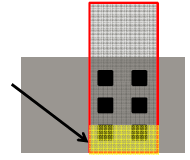
Virtuoso Layout Suite XL (VXL) provides a connectivity-aware environment. An interoperable digital block floorplan created in VXL can be later used in Innovus. To create an interoperable digital block floorplan in VXL:
- Create a top-level floorplan in VXL.
-
Use Launch -> Configure Physical Hierarchy (CPH) to create analog and digital softBlocks.
-
Define the digital softBlocks as blockType
DIGITAL. -
Create the top-level and softBlock layout views with Floorplan -> Generate Physical Hierarchy (GPH).
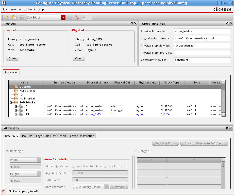
Refer to the Schematic-Driven Mixed Signal Design Flow chapter for more information on this step. -
- Optimize the top-level floorplan and reshape the softBlock boundaries (Level-1 editing) by using Virtuoso Floorplanner. See the Schematic-Driven Mixed Signal Design Flow chapter for more information on this step.
-
Optimize and align IO pins with Pin Optimizer.
-
Use Edit -> Advanced -> Align to fully align these IO pins with reference objects.
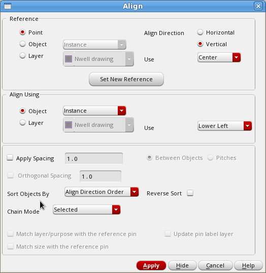
-
Make sure that the Placement Status of the pins is placed or fixed.
-
-
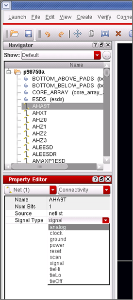
Define the correct Signal Type for power/ground nets. In Innovus, the power and ground nets are SPECIAL NETS. If they are defined as
signal, they will be treated as regular nets by NanoRoute.-
Select the net in the VXL Navigator and use the Property Editor assistant to check or change the signal type. Ideally the signal type is correctly defined in schematic as this will be propagated automatically to layout.
-
-
Create top-level supply routing with geometric wires (geometric routes). Power/Ground pre-routing needs to be created as geometric wires ("Part of Route : FALSE", nets that would be in the DEF SPECIALNETS section).
-
Use the Create -> Shape -> Geometric Wire after enabling GUI access for creating geometric wires by including the following in the
.cdsinitfile:; Enable the Create -> Shape -> Geometric Wire functionalityenvSetVal( "we" "mixedSignalWireEditingEnvironment" 'boolean t ) -
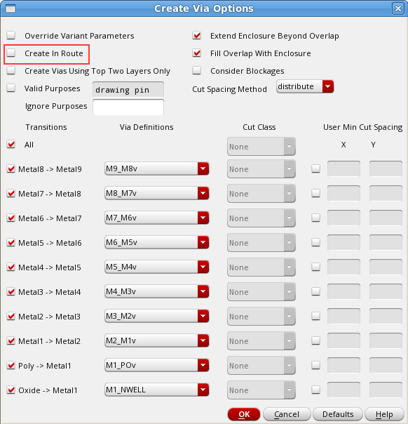
Make sure that the manually placed Vias (Create -> Via) are also geometric routes (Part of Route : FALSE). To achieve this, deselect the Create In Route on Create Via Options form.
-
If you want to convert symbolic wires to geometric wires on legacy IP, use the Edit -> Wiring -> Compose Trunks command.
Normal signal pre-routing has to be done with symbolic wires either manually with Create -> Wiring -> Wire or with automatic routing (In Virtuoso Space-based Router (VSR), select Route -> Automatic Routing).
-
-
Push down power/ground routing. The top-level supply routing can be pushed down into the digital block-level floorplan.
-
Select Floorplan -> Soft Block Update -> Push Into Blocks.
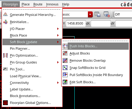
Refer to the Schematic-Driven Mixed Signal Design Flow chapter for more information on this step. -
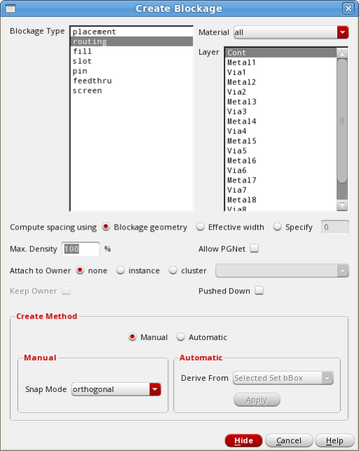
Create Placement and/or Routing (P&R) blockages in the digital block floorplan. The P&R blockages must be created as OpenAccess blockages:
-
Select Create -> P&R Objects -> Blockage.
-
-
Define interoperable constraints. Create the required routing constraints (diffpair, shielding, non-default rules, bus constraints, and so on) with Virtuoso Constraint Manager. These constraints are saved in the OpenAccess view and are
interoperable with Innovus.
Check the Routing Constraint Interoperability chapter for more information on this step. -
Run the OpenAccess Database Interoperability Checker (OA DB Checker). Check the OpenAccess Database Interoperability Checker chapter for more information on this step.
This is an example how to use custom settings to check for floorplan inconsistencies.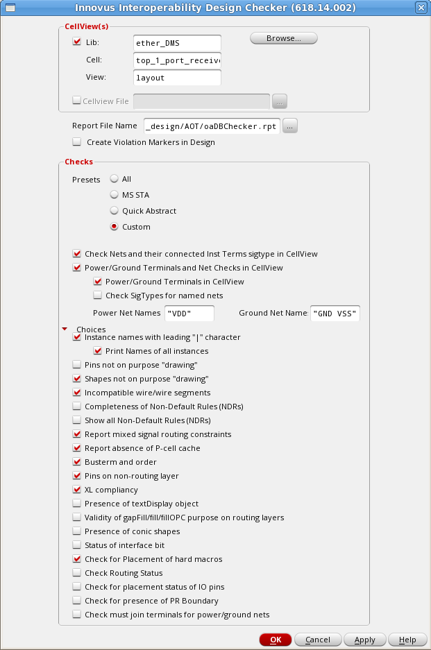
....
Performing
Check for existence of PG terms in Netlist....

INFO (CHECKER_DESGN-27): Found terminal ‘VSS’ with ground sigType in the
cellView.

INFO (CHECKER_DESGN-27): Found terminal ‘VDD’ with power sigType in the
cellView.

PASSED.
Checking SigTypes of named power and ground nets....
Performing
Check for existence of non-drawing shapes....PASSED.
Checking for pins on non-routing layers in the design....PASSED.Checking the incompatible wires/wire segments....PASSED.Checking for presence of pcell cache ......PASSED.Checking for XL compliancy.....PASSED.Checking placement status of hard macros...PASSED.Final SummaryType of checks PASSED FAILED-----------------------------------------------------------------------------Design Library Checks:Pin shape check for terminals PASSED'|' char in instance names FAILEDBus Annotation check FAILEDCheck Nets and their Inst terms' sig type FAILEDPower/Ground Checks PASSEDCheck signal types of named nets PASSEDShapes on drawing purpose PASSEDPins on non-routing layer check PASSEDUnsupported routing shapes PASSEDMS constraints check PASSEDPCell cache check PASSEDXL Compliancy check PASSEDPlacement status check PASSED -
Import the floorplan, placement and routing data in Innovus.
-
To enable mixed-signal interoperability flow, make the following settings at Innouvs startup:
setOaxMode -updateMode autosetViaGenMode -symmetrical_via_only trueFor more information, see the Design Data Preparation chapter.
-
Use
oaInwith the-filteroption to read only the object types that are chosen:oaIn <lib cell view> -filter {boundary pin_shapes blockages special_routing}For more information, see the Schematic-Driven Mixed Signal Design Flow chapter.
Now you should see all the floorplan objects created with Virtuoso XL in Innovus.
-
9.2 Understanding Symbolic and Geometric Routing
9.2.1 Differences Between Symbolic and Geometric Routing
Symbolic routing:
- Represents the routing used by automatic routers.
- Corresponds to DEF NETS section which are signal (default) routing.
- Contains path segments with matching end-points.
- Contains via origin matching with end-points.
- is contained in oaRoutes.
Geometric routing:
- is often used for power and ground and other hand-crafted nets.
- does not require paths, path segments and vias, and end points to match and be contained in oaRoutes.
- corresponds to DEF SPECIALNETS section which are special routing.
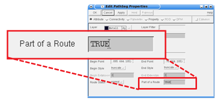
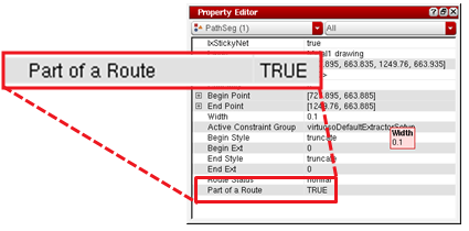
9.2.2 Identifying Symbolic Routing and Geometric Routing
- When you use the Property Editor GUI, the Part of a route field is true in case of symbolic routing and false in case of geometric routing.
- When you use Property Editor Assistant, invoked from the task assistant in Virtuoso, the Part of a route field is true in case of symbolic and false in case of geometric routing.
- When you use SKILL, it returns the ID number in case of symbolic routing and no value in case geometric routing.
9.2.3 Identifying the Route Status for Symbolic and Geometric Routing
- For Property Editor, the route status in case of symbolic and geometric routing is Normal, Fixed, and Lock.
- For Property Editor Assistant, the route status in case of symbolic and geometric routing is: Normal, Fixed, and Lock.
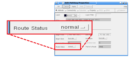
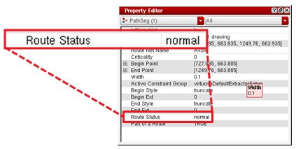
- In case of SKILL, the route status is returned as: nil, locked, fixed, and normal.
9.2.4 Ways of Creating Wires in Virtuoso and Innovus Environment
| Virtuoso | Innovus |
|
Geometric (SPECIALNETS)
|
Geometric (SPECIALNETS)
Note: To create SPECIALNETS for Innovus (nets that would be in the DEF SPECIALNETS section), geometric routes need to be created in Virtuoso. To enable GUI access for creating geometric routes, include the following in the .cdsinit file.
|
Symbolic (NETS)
|
Symbolic (NETS)
|
Note: In Innovus, the usage is for flip-chip routing and only geometric routing is allowed.
9.3 Locking a Net Using Virtuoso Space-Based Router (VSR)
9.3.1 Locking a partially routed net
To lock a partially routed net, ensure that:
- The existing wiring objects (pathSegs, vias, and paths) are locked.
- Rerouting the design can complete the net, but the pre-existing wiring objects do not change.
- The new objects that complete the route are not locked. You must lock them explicitly.
9.3.2 Locking a net that is completely unrouted
To lock a completely unrouted net, ensure that:
- There are no wiring objects to lock.
- Rerouting the design results in routing the net.
- The wiring objects are not locked. You must lock them explicitly.
9.3.3 Locking a completely routed net
To lock a completely routed net, ensure that:
- Every wiring object on the net is locked.
- Rerouting the design does not alter any wiring object on the net.
9.3.4 Unlocking Nets
To unlock the nets:
- Delete the constraints in Virtuoso Constraints Manager.
- Select the nets in the Navigator.
9.3.5 Highlighting Locked Nets
Highlight locked nets by clicking the highlight icon on the Virtuoso Space-Based Router tool bar. Clicking the icon a second time removes the highlighting.
9.4 Editing Net Attributes in Virtuoso
To edit net attributes,
- Select the net in the Navigator.
- Set the Signal Type using the pull-down menu in the Property Editor.
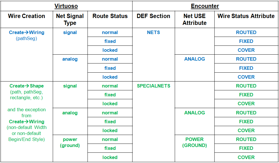
9.5 Wire/Net Mapping Between Virtuoso and Innovus
The following table summarizes the wire/net mapping between Virtuoso and Innovus:
9.6 Handling of Wires from Virtuoso in Innovus
9.6.1 Conversion of Wires to DEF SPECIALNETS in Innovus
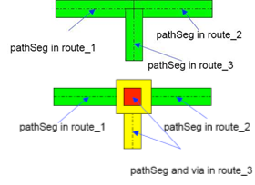
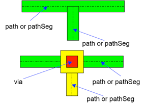
Mixed Signal users may face an issue where some wires or wire segments created in Virtuoso may change to DEF SPECIALNETS when brought into Innovus. For example, sometimes, wires created using wire edits, wire assistant auto route, and from Virtuoso Space-based Router may be converted to DEF SPECIALNETS in Innovus. This happens because Innovus does not support all the attributes associated with a wire when brought from Virtuoso (although there is no change in physical shape). Innovus looks for some specific attributes to retain properties on wires brought from Virtuoso. One of these attribute is related to the wire extension. If the wires follow the ½ width or 0 width extension, the wire attribute is retained. For other variable extensions, Innovus will convert the wires to DEF SPECIALNETS.
Examples of situations where Innovus would convert a wire to DEF SPECIALNETS
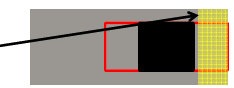
Wire editor and Wire Assistant auto route can create modified extents ,which will cause the conversion of wires to DEF SPECIALNETS. Modified extents are mainly used for:
-
DRC coverage
In this example, the via is smaller than the wire width. The extents can be modified to adjust the corners. Note that this can occur from either the creation of vias or the use of custom via or via variants
-
Via Maximization
In this example, the code attempts to create an array of vias between the shapes. The minNumCut rules may or may not kick in and require additional vias but if there is sufficient room to add more, the router will try.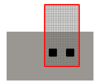
-
Directional width and wrong-way routing
In this example, either because of required directional width rules from the foundry or because of tapering and same layer wrong way routing, the router creates custom extents. There is no clean work around for this one in Innovus if we extend or truncate. The result is that the code has been simplified to do similar things for all cases with single layer or layer change.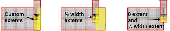
For routing layers that have different preferred direction and non-preferred direction widths, Innovus expects the following
In the DEF, a vertical default route in the NETS section will have a width of 0.10 μm with extension of 0.05 μm, while a horizontal route will have a width of 0.14 μm with extension of 0.05 μm, as shown in the DEF NETS routing example below:
-net1 (…) + ROUTED metal2 (1 0) (1 2) (3 2) (33);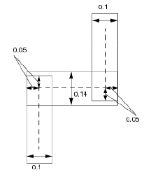
In more advanced nodes, wider widths are required for non-preferred direction. The following example shows route with wrong-way segment:
LAYER METAL2...WIDTH 0.1 ;PROPERTY LEF58_WIDTH "WIDTH 0.14 WRONGDIRECTION ;" ;...END METAL2
OrLAYER METAL2...PROPERTY LEF58_WIDTHTABLE "WIDTHTABLE 0.1 ... ;WIDTHTABLE 0.14 ... WRONGDIRECTION ; " ;...END METAL2
Notes
- Wires created through the
run_vsrcommand in Innovus do not get affected. - In Innovus:
- DEF NETS is treated as symbolic wiring structure (centerline/endpoint connected)
- DEF SPECIALNETS is geometrically connected (so any overlap or abutment is treated as connected)
9.6.2 Implications of the Conversion in Innovus
The conversion of wires to DEF SPECIALNETS has the following implications in Innovus:
- The conversion can be problematic because some parts of the flow in Innovus, such as buffer insertion on special nets, would not work well.
- Sometimes a special setting may be needed in Innovus. For example, parasitic extraction needs special settings to extract special nets.
- If the completed wires are not intended to be touched by Innovus tools, put a
skip_routingattribute on those nets in Innovus. To do so, you can use one of the following commands:setAttribute -net net_name -skip_routing true
OrdbSet $net_ptrs.skipRouting true(Use thedbGetcommand to pass nets with a specific attribute to thedbSetcommand.)
Note: To bring back the wires with the original attribute to Virtuoso after the round trip, for example after VXL > Innovus >VXL, set the following mode before opening an OpenAccess database in Innovus: setOaxMode –updateMode true
9.6.3 Addressing the Conversion Issue
You can use post route calls to clean up the modified/variable extents in Virtuoso. Use the following command in Virtuoso after all the wire edits are done:route_optimize –via_extent_optimization truncate –max_iterations 0
The above command changes the wiring and verify DRC correctness internally.
The run_vsr interface automatically calls the route_optimize command to minimize the above issue.
To find out which wires will be affected in Virtuoso, you can use OpenAcess DataBase Interoperability Checker. Use the Check for incompatible wire/wire segments option on the Design page of the OA DB Checker to identify the wires that will be affected when taken into Innovus.
Note: In Innovus, you can use the defOut command to see if the corresponding net is in the SPECIALNETS or NETS section.
9.6.4 How To Prevent the Conversion Issue
In some situations, a pathSeg may have Part of a Route set to false and be represented as DEF SPECIALNETS but the corresponding via might have Part of a Route set to true and be represented as DEF NETS. In this case, when the design is taken to Innovus, there will be problems during the optimization step because NanoRoute might delete the vias.
To fix this problem within Virtuoso, you can convert the via from DEF NETS to DEF SPECIALNETS by using the Skill routine defined below as follows:
In CIW:
load("partOfRtFalseForNetsDefinedInFile.il")
partOfRtFalse("library" "cell" "view" "filewithPGnets.txt")
In the above call, replace the library, cell, and view as required. For example, if your library is amsPLL, cell is AA and view is layout, the call would be as follows:
partOfRtFalse ("amsPLL" "AA" "layout" "filewithPGnets.txt")
The filewithPGnets.txt lists the power and ground nets in the design, such as VDD, VSS , and so on.
Skill routine:
procedure(partOfRtFalse(library cell view fileName "t")
let( (cv fp mylist mylist1 l_shape v_shape newmlist newvlist)
        envSetVal("layout" "extractKeepShapeAssignment" 'boolean t)
; check if the file passed exists
unless(isFile(fileName)
  error("Please pass an existing file to the procedure")
 );unless
; open the file for read and get list of nets
; in it into mylist variable
fp = infile(fileName) ; In their flow hard code the location of the file and call it nets.txt.. check
 when(fp
      while( gets( nextLine fp)
       mylist = append(parseString(nextLine "\n ") mylist)
        )
   close(fp)
   );when
; make sure the elements in mylist are nets existing in the current design
; provide warning for net names present in the input file but not in the currently open design.
cv = dbOpenCellViewByType(library cell view)
;cv = geGetEditCellView()
mylist1 = setof(elem mylist
                !member(elem cv~>nets~>name)
              )
when(mylist1
  warn("Nets %L listed in the input file %s are not present in the current cellview %s/%s/%s" mylist1 fileName cv~>libName cv~>cellName cv~>viewName)
 );when
mylist = setof(elem mylist
                member(elem cv~>nets~>name)
             )
when(mylist
printf("List of nets present in the text file are: %L\n" mylist)
;Un-Comment this block section if need to work on pathSegs.
; Here working on pathSeg
l_shape=setof(obj cv~>shapes obj~>objType == "pathSeg")
                 when(newmlist=setof(x l_shape member(x~>net~>name mylist))
                  when( newmlist~>route!=nil && newmlist~>net~>name!=nil
  foreach(targetshp newmlist
                         ;targetshp~>lxStickyNet=t
 targetshp~>route~>objects=remove(targetshp targetshp~>route~>objects)
                );foreach
          );when
         );when
; Here working on stdVia defs
v_shape=setof(vobj cv~>vias vobj~>objType == "stdVia")
        when(newvlist=setof(x v_shape member(x~>net~>name mylist))
                when(newvlist~>route!=nil && newvlist~>net~>name!=nil
                foreach(targetvshp newvlist
                ;targetvshp~>lxStickyNet=t
                targetvshp~>route~>objects=remove(targetvshp targetvshp~>route~>objects)
        printf("Attribute Part Of Route set to FALSE for Vias with net name %L...completed.\n" targetvshp~>net~>name)
                );foreach
                );when
        );when
);when mylist
;dbSave(cv)
;dbClose(cv)
);let
);procedure
9.7 Wiring Connectivity in Innovus
- Nets with the
COVERattribute:
- Are not modified by Innovus optimization or routing.
- Cannot be moved by either automatic layout or interactive commands.
- Nets with the
ANALOGattribute:
- Are not modified by optimization
- This attribute can be imported from the OpenAccess database or specified within Innovus.
- NanoRoute routes analog nets unless you specify the following command before routing:
setNanoRouteMode -route_skip_analog true
- Early Global Route routes analog nets by default.
- Connectivity extraction in verify connectivity based on shape overlap
geomConnect
- Innovus wire editing will preserve the connectivity and DEF representation.
9.8 Wiring Extraction in Innovus
In case your pre-routes have been created with geometric wires (outside a route/ special nets), you need to make sure to use the following option to get you pre-routes correctly extracted:
Extraction within Innovus should enable special net handling in order to perform extraction on analog/special nets:
setExtractRCMode -specialNet true
You can specify this option in default and detail mode of extraction. Special nets are always extracted in sign-off extraction mode.
Innovus wire editing will preserve connectivity and DEF representation.