3
LEF Syntax - Layer (Implant)
This chapter contains information about the following topics:
Layer (Implant)
LAYERlayerNameTYPE IMPLANT ; [MANUFACTURINGGRIDvalue ;] [MASKmaskNum;] [WIDTHminWidth;] [SPACINGminSpacing[LAYERlayerName2] ;] ... [PROPERTYpropNamepropVal;] ... [PROPERTY LEF_CDN_AREA "AREAminArea; " ;] [PROPERTY LEF_CDN_COREEDGELENGTH "COREEDGELENGTHminLength[EXCEPTADJACENTLENGTH {exactEdgeLengthadjLength[EXACTADJACENTLENGTH]}...] ; " ;] [PROPERTY LEF_CDN_CORNERSPACING "CORNERSPACINGspacing[ALIGNEDONLY] [CHECKIMPLANTGROUPONLY] ; " ;] [PROPERTY LEF_CDN_MINENCLOSEDAREA "MINENCLOSEDAREAarea; " ;] [PROPERTY LEF_CDN_MINSTEP "MINSTEPminStepLengthMINADJACENTLENGTHminAdjLength; " ;] [PROPERTY LEF_CDN_SPACING "SPACINGminSpacing[LAYERlayerName2] [HORIZONTAL|VERTICAL PRLprl][EXCEPTABUTTED] [EXCEPTCORNERTOUCH] [LENGTHlength] [INTERSECTLAYERSlayerNameList...] ; " ;] [PROPERTY LEF_CDN_WIDTH "WIDTHminWidth[LAYER {layerName2| ANY}] [ZEROPRL [MAXWIDTHmaxWidth]] [EXCEPTCORNERTOUCH] [LENGTHlength] [CHECKIMPLANTGROUPgroupName] ; " ;]
END layerName
Defines implant layers in the design. Each layer is defined by assigning it a name and simple spacing and width rules. These spacing and width rules only affect the legal cell placements. These rules interact with the library methodology, detailed placement, and filler cell support. You must define implant layers separately, with their own layer statements.
Typically, you define high-drive cells on one implant layer and low-drive cells on another implant layer. The following example defines high-drive cells on implant1 and low-drive cells on implant2. Both implant layers cover the entire cell. The placer and filler cell creation attempt to legalize the cell overlaps in abutting rows to ensure that the minimum width and spacing values are met.
LAYER implant1 #high-drive implant layer
TYPE IMPLANT ;
WIDTH 0.50 ; #implant rectangles must be >=0.50 microns wide
SPACING 0.50 ; #implant rectangles must be >=0.50 microns apart
END implant1
LAYER implant2 #low-drive implant layer
TYPE IMPLANT ;
WIDTH 0.50 ; #implant rectangles must be >=0.50 microns wide
SPACING 0.50 ; #implant rectangles must be >=0.50 microns apart
END implant2
Assume that the high-drive cells and low-drive cells are completely covered by their respective implant layers. Because there is no spacing between implant1 and implant2 specified, you might see a placement like that illustrated in Figure 3-1.
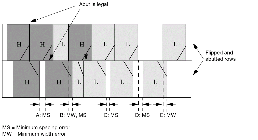
Note that you can correct A, C, D, and E by putting in filler cells with the appropriate implant type. However, B cannot be corrected by a filler cell—either the placer must avoid it, or you must allow the filler cell or post-process command to move cells or modify the implant layer to correct the error.
Defining Implant Layer Properties to Create 32/28 nm and Smaller Nodes Rules
You can include implant layer properties in your LEF file to create DRC rules that currently are not supported by existing LEF syntax. The properties are specified inside the LAYER IMPLANT statements, where they can be seen with other rules.
Before you can reference them, properties must be defined at the beginning of the LEF file in the PROPERTYDEFINITIONS statement, immediately before the first LAYER statement.
-
Properties belong to the
LAYERobject and have a type ofSTRING. -
The property names used for these rules all start with
LEF_CDN_.
All properties use the following syntax within the LEF PROPERTYDEFINITIONS statement:
PROPERTYDEFINITIONS
LAYER propName STRING ["stringValue"] ;
END PROPERTYDEFINITIONS
The property definitions for the implant layer properties are as follows:
PROPERTYDEFINITIONS
LAYER LEF_CDN_AREA STRING ;
LAYER LEF_CDN_COREEDGELENGTH STRING ;
LAYER LEF_CDN_CORNERSPACING STRING ;
LAYER LEF_CDN_MINENCLOSEDAREA STRING ;
LAYER LEF_CDN_MINSTEP STRING ;
LAYER LEF_CDN_SPACING STRING ;
LAYER LEF_CDN_WIDTH STRING ;
END PROPERTYDEFINITIONS
Area Rule
An area rule can be used to specify the minimum area on the implant layer.
You can use the following property definition:
PROPERTY LEF_CDN_AREA
"AREA minArea
; " ;
|
Specifies the minimum area on the implant layer. |
Core Edge Length Rule
A core edge length rule can be used to indicate that the edge length of an implant shape of a CORE (standard) cell must be greater than or equal to the specified minimum length.
You can create a core edge length rule by using the following property definition:
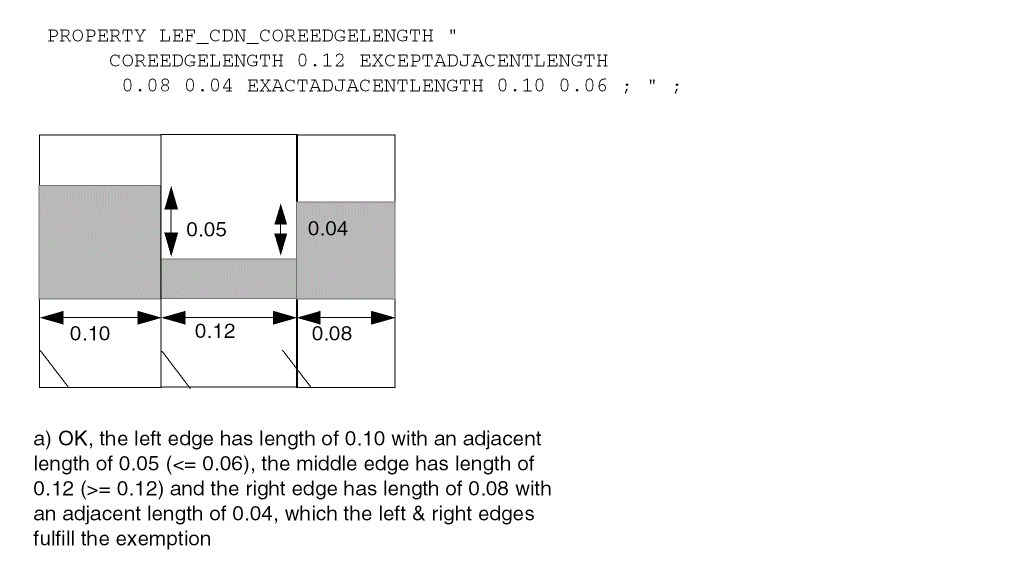
PROPERTY LEF_CDN_COREEDGELENGTH "COREEDGELENGTHminLength[EXCEPTADJACENTLENGTH {exactEdgeLengthadjLength[EXACTADJACENTLENGTH]}…] ; " ;
Figure 3-2 Example of Core Edge Length Rule
Corner Spacing Rule
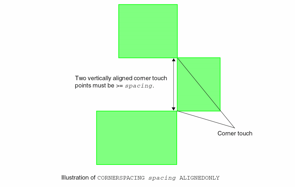
A corner spacing rule can be used to specify the spacing between two corner touch points.
You can create a corner spacing rule by using the following property definition:
PROPERTY LEF_CDN_CORNERSPACING
   "CORNERSPACING spacing [ALIGNEDONLY]
       [CHECKIMPLANTGROUPONLY]
   ; " ;
Corner Spacing Rule Examples
Figure 3-3 Illustration of Corner Spacing Rule
-
The following example illustrates a corner spacing rule with
CHECKIMPLANTGROUPONLY:PROPERTYDEFINITIONS
LIBRARY LEF_CDN_IMPLANTGROUP STRING "
IMPLANTGROUP IPG1 LAYER IP1 IP2 BASEDLAYER IP1 ;";
END PROPERTYDEFINITIONS
On layerIP1:PROPERTY LEF_CDN_CORNERSPACING "
CORNERSPACING 0.15 ALIGNEDONLY
CHECKIMPLANTGROUPONLY ; " ;
Figure 3-4 Example of the Corner Spacing Rule with CHECKIMPLANTGROUPONLY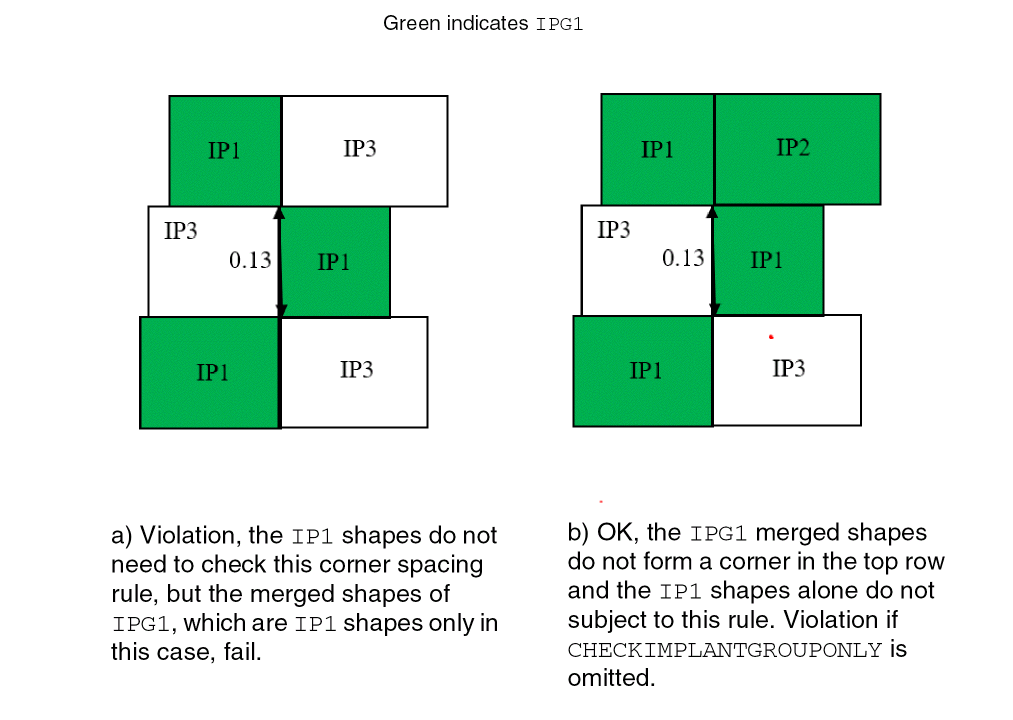
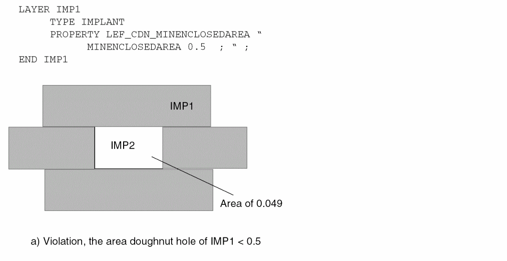
Min Enclosed Area Rule
A min enclosed area rule can be used to specify the minimum area that is enclosed by shapes on the current implant layer.
You can create a min enclosed area rule by using the following property definition:
PROPERTY LEF_CDN_MINENCLOSEDAREA
 "MINENCLOSEDAREA area
  ; " ;
|
Specifies the minimum area that is enclosed by shapes on the current implant layer. |
|
Figure 3-5 Example of the Min Enclosed Area Rule
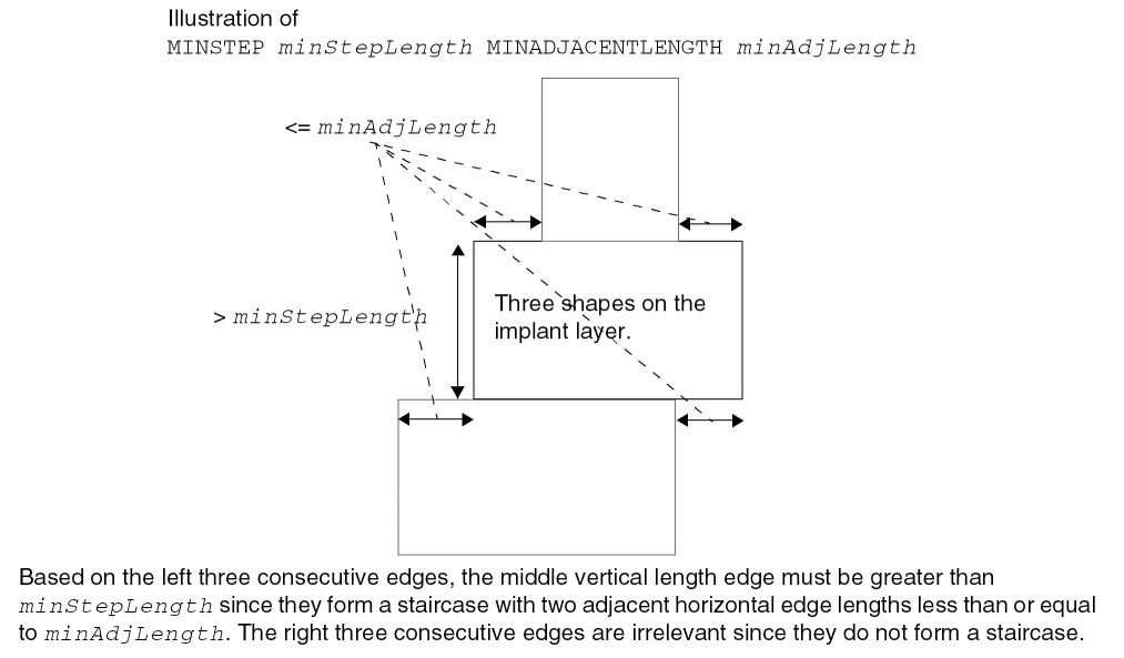
Min Step Rule
You can create a min step rule by using the following property definition:
PROPERTY LEF_CDN_MINSTEP"MINSTEPminStepLengthMINADJACENTLENGTHminAdjLength; " ;
Figure 3-6 Illustration of the Min Step Rule
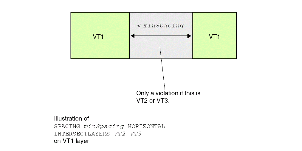
Spacing Rule
A spacing rule can be used to specify the spacing requirements for the current implant layer. You can create a spacing rule by using the following property definition:
PROPERTY LEF_CDN_SPACING "SPACINGminSpacing[LAYERlayerName2] [HORIZONTAL|VERTICAL PRLprl][EXCEPTABUTTED] [EXCEPTCORNERTOUCH] [LENGTHlength] [INTERSECTLAYERSlayerNameList...] ; " ;
Spacing Rule Examples
Figure 3-7 Illustration of the Spacing Rule
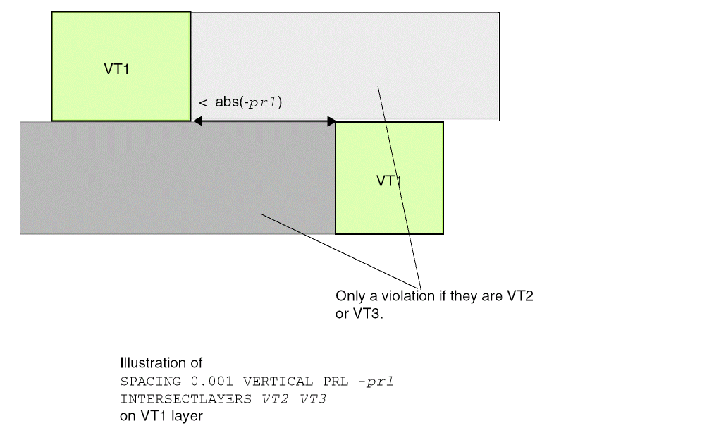
Figure 3-8 Illustration of the Spacing Rule
Width Rule
A width rule can be used to specify the width requirements for the current implant layer. You can create a spacing rule by using the following property definition:
[PROPERTY LEF_CDN_WIDTH"WIDTHminWidth[LAYER {layerName2| ANY}] [ZEROPRL [MAXWIDTHmaxWidth]] [EXCEPTCORNERTOUCH] [LENGTHlength] [CHECKIMPLANTGROUPgroupName] ]; " ;
Width Rule Examples
-
The following example illustrates a Width rule with
EXCEPTCORNERTOUCH:
Figure 3-9 Example of the Width Rule with EXCEPTCORNERTOUCH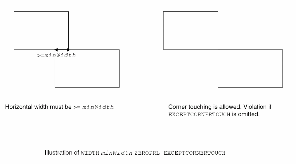
-
The following example illustrates a Width rule with
CHECKIMPLANTGROUP:PROPERTYDEFINITIONS
LIBRARY LEF_CDN_IMPLANTGROUP STRING "
IMPLANTGROUP IPG1 LAYER IP1 IP2 IP3 BASEDLAYER IP1 ;
IMPLANTGROUP IPG2 LAYER IP1 IP4 BASEDLAYER IP1 ; " ;
END PROPERTYDEFINITIONS
On layerIP1:PROPERTY LEF_CDN_WIDTH "
WIDTH 0.15 LAYER IP2 ZEROPRL
CHECKIMPLANTGROUP IPG1 ; " ;
Figure 3-10 Example of the Width Rule with CHECKIMPLANTGROUP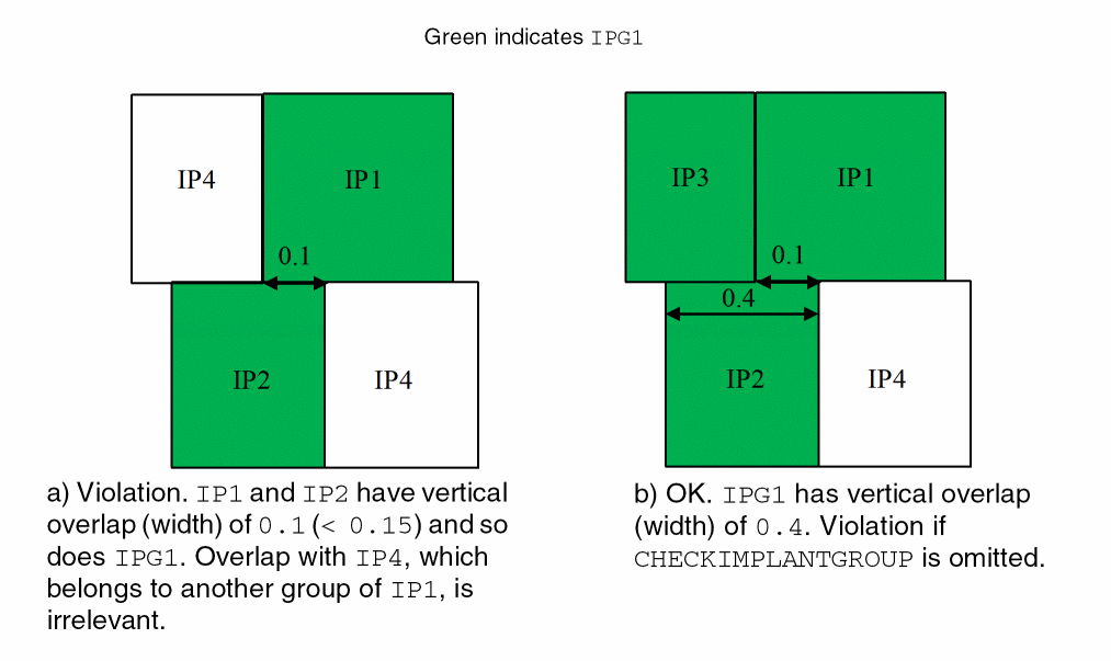
-
The following example illustrates a Width rule with
MAXWIDTH:
On layerIP1:PROPERTY LEF58_WIDTH "
WIDTH 0.15 ZEROPRL MAXWIDTH 0.4 ;
WIDTH 0.15 LAYER IP2 ZEROPRL MAXWIDTH 0.4 ; " ;
Figure 3-11 Example of the Width Rule with MAXWIDTH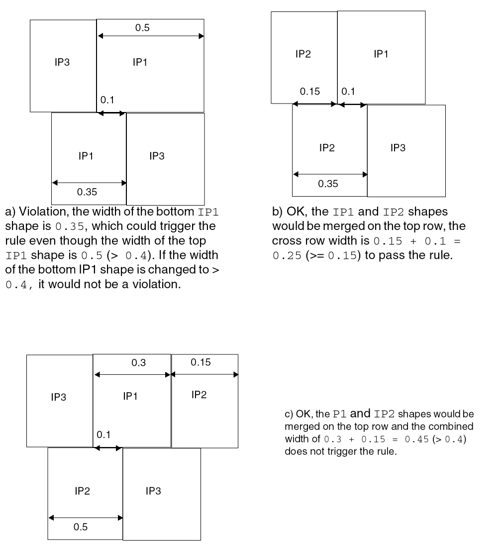
Return to top