2
NC-Verilog Integration Control Commands
This chapter describes the commands and forms you can use from the Virtuoso® Verilog Environment for the NC-Verilog Integration window.
- About the Main NC-Verilog Window
- Commands Menu
- Setup Menu
- Results Menu
- Fixed Menu
- Customizing Command Form Options
About the Main NC-Verilog Window
The Virtuoso® Verilog Environment for the NC-Verilog Integration window (main NC-Verilog window) gets displayed when you first enter the NC-Verilog Integration Environment. The main NC-Verilog window provides access to simulation commands, command forms, and support tools.
The following figure shows the main NC-Verilog window:
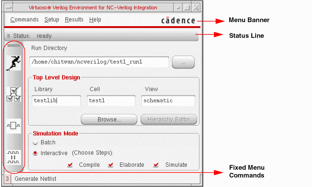
The main NC-Verilog window sections include the status line, menu banner, fixed menu, Run Directory field, Top Level Design selection fields and Simulate Options fields.
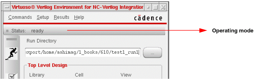
Status Line
The Status Line shows the current operating mode of the current design. The following figure shows the Status Line:
Menu Banner
The Menu Banner lets you access all the commands, forms, and tools required for controlling the simulation with the help of the following set of options:
Fixed Menu
The Fixed Menu provides access to the frequently used commands. For more information on its options, refer to Fixed Menu.
Run Directory
The Run Directory field is used to specify the name of the directory for design netlisting, simulation and waveform database creation. You can specify a new or already existing directory name in this field. For more information, refer to Initializing a Design.
Top Level Design Options
Use the Top Level Design options to specify the Library, Cell and View name of the top level design.
- Browse is used to find and open libraries, cells, and cellviews.
- Hierarchy Editor is used to display the Hierarchy Editor to edit the configuration and define the design hierarchy for netlisting and simulation. This option can only be used if the top level cellview is a 5.X configuration.
Simulate Options
Simulator Mode specifies the kind of simulation that you require. It can be either Interactive or Batch.
- In Interactive simulation you can select the steps to Compile, Elaborate and Simulate. You may select to omit performing any one of these. In this mode, the system invokes the SimControl user interface after it successfully compiles and elaborates the design. You can then interactively simulate and debug the design using the SimControl user interface.
- Batch simulation results in the execution of all the three options: Compile, Elaborate and Simulate in one go. In batch mode of simulation, SimControl user interface is not invoked.
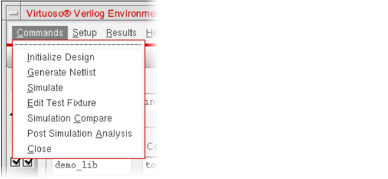
Commands Menu
-
Initialize Design
Starts the NC-Verilog simulator. You must initialize design before you can access the other fixed menu commands. -
Generate Netlist
Triggers the OSS netlist() routine to generate an incremental hierarchical netlist in the specified run directory. -
Simulate
Simulates the design in either interactive or batch mode. -
Edit Test Fixture
Displays the Edit Test Fixture dialog box. This is used to specify the stimulus file or the test bench for simulation.
The default stimulus file and test bench created by the netlister are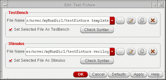
testfixture.verilogandtestfixture.template, respectively. You can edit these default files or copy them to create new files using the Edit Test Fixture form. For more information, refer to Chapter 6, “Working with the Stimulus”. -
Simulation Compare
Invokes the SimCompare tool to compare the golden and test SST2 databases. You need to specify these databases and other options for comparison using the Simulation Comparison Setup form. -
Post Simulation Analysis
Displays the Post Simulation Analysis form. Use this form to initiate cross-selection of objects between SimVision and Virtuoso Schematic Editor using the available simulation data of a design.
For details, see Cross-Selecting Objects Using Simulation Data. For detailed information on SimVision, see the Cadence SimVision Analysis Environment documentation suite.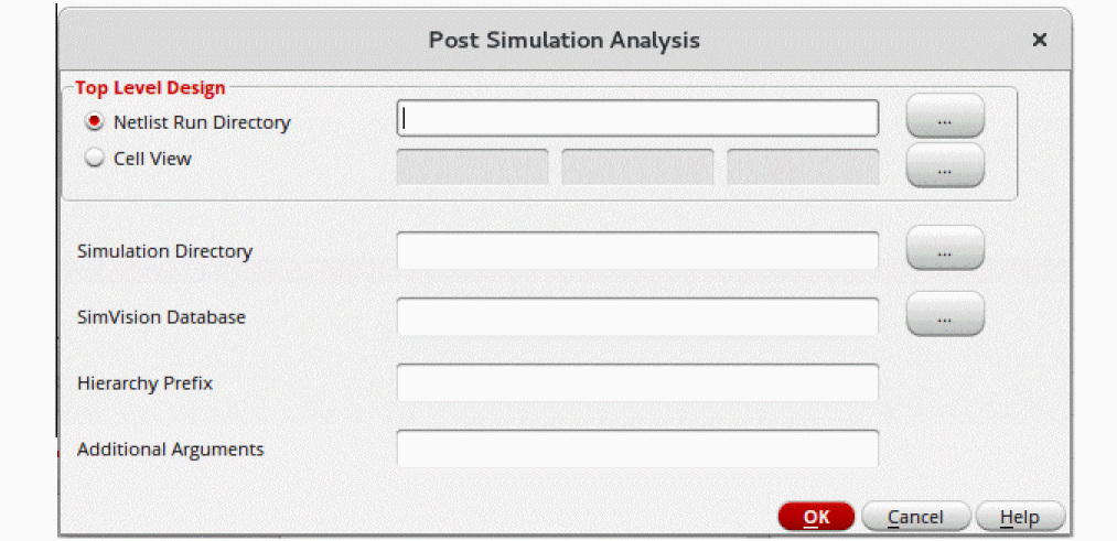
-
Close
Terminates the current simulation.
Setup Menu
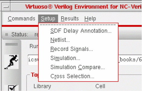
The following tables describe the below mentioned Setup menu options:
SDF Delay Annotation
Selecting this option displays the SDF Delay Annotation Setup form. In this form, you can specify an SDF delay file to be prepared for ncelab to annotate. The SDF delay file will be converted from the Virtuoso Design Editor L name space to Verilog name space by running sdf2sdf3 (this is an optional feature). After this, it is compiled using ncsdfc. Next, the compiled SDF file is stored in the run directory under the name <Original SDF File Name>.compiled. Finally, an SDF command file will be created which will then be passed on to ncelab during elaboration time.
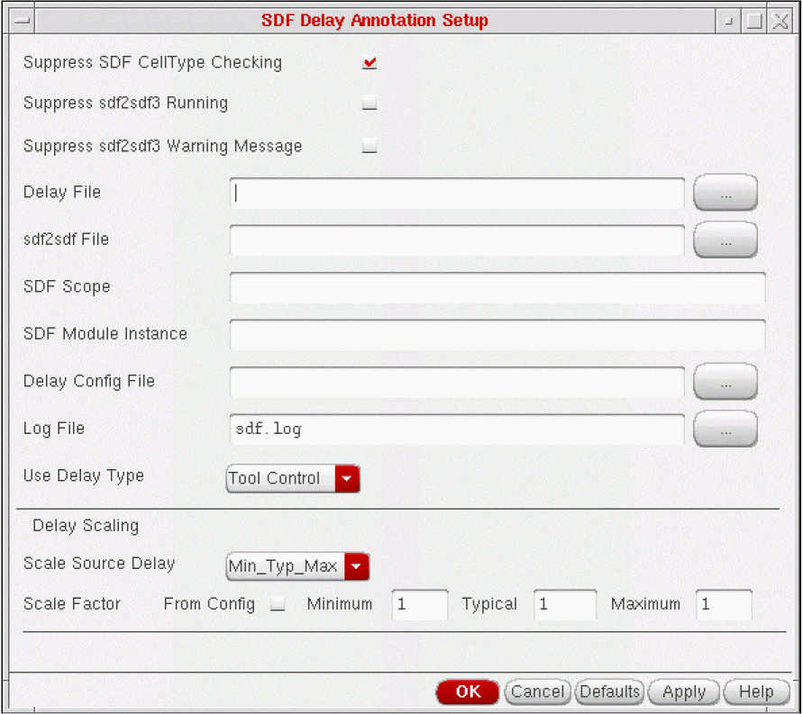
Setting the Delay Annotation Options
The following table describes the various delay annotation options:
Example of Determining Delays
The following sample shows an SDF delay entry for a timing path from A to Z.
SDF Delay File: (IOPATH A Z (2:3:5))
The scaling example is based on the following delay annotation settings:
Scale Source Delay:    Maximum
Scale Factor:       Minimum = .5, Typical = 1,    Maximum = 2
Use Delay Type:    Minimum
The simulator uses the following process to scale the delays and to determine which single delay is annotated for simulation:
- The Scale Source Delay setting specifies to use the maximum delay in the SDF file as the initial value for scaling Minimum, Typical, and Maximum delay values.
-
The initial value multiplied by the factor value results in the scaled delay value, as shown in the following table.
Minimum Typical Maximum - The Use Delay Type setting specifies which scaled delay to annotate to the simulation. In the sample setting, Minimum is specified.
- The value of 2.5 is annotated to the simulation.
Netlist
Selecting this option displays the Netlist Setup form. You use this form to specify options for the design to netlist and the views to netlist.
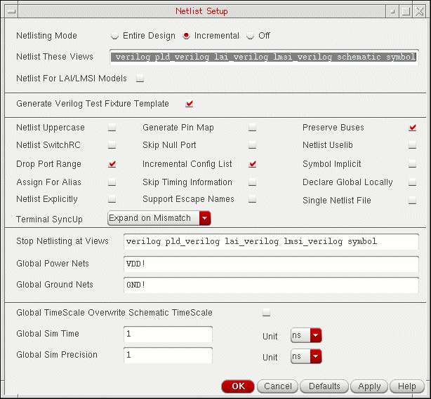
The following tables describe how the netlisting options affect netlisting.
| Option | Description |
|---|---|
|
Specifies whether or not you need the netlister to generate the test fixture template. |
| Option | Description |
|---|---|
|
Netlister uses all
Cells that do not have the
To attach the
lai_verilog or lmsi_verilog view property to an instance on a VSE schematic, use the Edit – Properties command. The Edit – Properties command appears on the schematic window. Refer to the Virtuoso Schematic Editor L User Guide for more information about using the Edit – Properties command to attach an lai_verilog or lmsi_verilog view property. |
|
|
Generates a netlist in all uppercase letters. This option creates compatible modules that are disparate in case. |
|
|
Instructs the netlister to create the pin mapping files necessary to convert Standard Delay Files (SDF) pin names to NC-Verilog pin names. Select this option only when you are ready to backannotate. This option is required when the pin names for a symbol in your schematic differ from those in the Verilog library model description. After you create your pin map, your entire design is netlisted automatically to ensure that the netlister creates pin maps for the entire design. |
|
|
Instructs the netlister to preserve buses (vectors) in the resulting netlist. If this option is off, the netlister expands vector nets to single-bit equivalents (scalars) in the resulting netlist. For more information on bus constructs, refer to Bus Constructs. |
|
|
Specifies that netlisting includes user-defined RC switch properties. |
|
|
Specifies that the netlister automatically adds the |
|
|
Suppresses printing of the net name during instance port formatting. |
|
|
When enabled, specifies that the netlister uses an assignment statement for patches between nets. When disabled, specifies that the netlister applies the default |
|
|
When enabled, causes the netlister to ignore timing information assigned to instances in the design. |
|
|
Generates name-based port lists (using connection-by-name syntax) for modules in Verilog views. Turn this option off to generate order-based port lists.This option does not apply to instances whose master module is generated by the netlister. For example, the netlister converts all schematics into Verilog modules. For instances of these modules, the netlister always creates order-based port lists. |
|
|
When enabled, causes the netlister to include escaped names in the netlist. |
|
|
When selected, generates a single verilog netlist instead of multiple netlists (one for each module). The netlist file is generated in the current simulation run directory with the name |
|
|
Controls the level of hierarchy at which netlisting stops. After netlisting a cell, the netlister checks whether the view netlisted is on this stop list. If it is, the netlister stops expansion of the design for this cell. The order of views in the stop list is irrelevant. For example, if the stop list is functional verilog symbol, the netlister checks each netlisted cell to determine if it contains a functional, verilog, or symbol view. If it does, the netlister stops netlisting for that cell. If not, it goes on to the next cell in the design library. |
|
|
Specifies how to synchronize terminals between an instance and its switched master. You can choose from the following three options:
You can also set the
hnlVerilogTermSyncUp variable in the .vlogifrc file. The possible values are mergeAll, honorSM, and nil (default).For more details, refer to Synchronizing Terminals. |
| Option | Description |
|---|---|
|
Specifies the global net names you want netlisted with the supply1 wire type. Supply1 wire types are driven to logic state 1. The net names you specify must conform to global naming conventions as described in the Virtuoso Schematic Editor L. |
|
|
Specifies the global net names you want netlisted with the supply0 wire type. Supply0 wire types are driven to logic state0. The net names you specify must conform to global net naming conventions as described in the Virtuoso Schematic Editor L. |
|
|
Specifies that the defined Global Time Scale variables (described below) overwrite any time values or units defined within a schematic. The results may vary depending on the various factors. For more information, refer to Results Dependency. |
|
|
When enabled, lets you declare global signals locally. When disabled, causes the netlister to use the default signals (Global Power Nets and Global Ground Nets). |
|
|
Specifies the units for the global simulation time value. The valid values are s |
|
|
Specifies a global precision value for the global simulation time |
Bus Constructs
Bus constructs that cannot be represented with Verilog bus constructs are represented by using in-line concatenation, a Verilog feature. In some cases, bus names that are bundled or that are part of aliasing schemes are mapped to new names because NC-Verilog does not support certain bundling schemes. Mapped bus names are prefixed by cdsbus and have a sequence number assigned. The sequence number is a function of how many names are mapped. The following examples illustrate how bundled signals are mapped:
Adding Directives
The netlister automatically adds the 'uselib directive only when the stop view for a cell is functional or behavioral or system. When the stop view for a cell is verilog or symbol,
you must add the
lmoToolPath
property to the library that contains the cell. Refer to the following steps for adding directives:
- Choose the Tools – Library Manager command from the CIW menu banner.
- Specify the library by clicking on the library name in the Library Manager window.
- Choose the Edit – Properties command from the Library Manager menu banner.
- Select the Add command from the Library Property Editor.
- In the Add property form, enter the values as shown below:
- Click OK on the Add Property Form.
- Click OK on the Library Editor form.
The lmoToolPath property is added to the specified library.
schematic stop view.For more information about adding library properties, refer to the Library Manager User Guide .
Results Dependency
The results for Global TimeScale Overwrite Schematic TimeScale option vary depending on the following:
- Whether this option is enabled
- Whether your schematic has an assigned time scale (that is, any time scale values or units
The table below describes the possible outcomes in various conditions:)
| Option Enabled | Option Disabled | |
|---|---|---|
For more information on netlisting, refer to Chapter 5, “Netlisting.”
Record Signals
Specifies a set of signals to trace and save in the SHM database. The SHM database stores waveform displays. On selecting this option, the Record Signals Setup form is displayed.
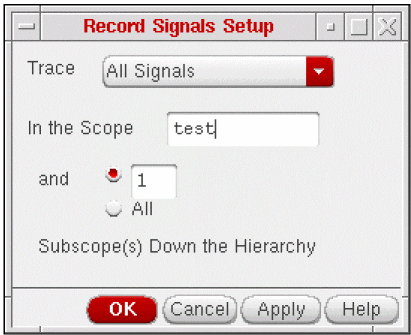
The following table gives the description of the various options on the Record Signals Setup form:
| Option | Description |
|---|---|
|
Tells the system to probe a set of signals. You specify the set of signals with the cyclic button. For information on signal sets, refer to Signal Sets |
|
|
Specifies the scope of the verilog design under simulation in which the specified object(s) is to be probed and how many scope levels to descend when searching for objects to probe if a scope is specified. You must specify one of the following arguments:
|
Signal Sets
The following table describes the various signal sets you can specify in the Trace option:
- The scope(s) named in an argument
- The subscopes specified with the In the scope option
- The current debug scope (if no scope(s) or object(s) is named in an argument)
Record Signals for Batch Simulation
Signals are saved only when the simulation is run in the interactive mode. In order to save signals in Batch Mode, you should perform the following steps:
-
Create a new file and fill in the kind of signals to probe following:
-
For Top Level I/O
database -open shmWave -shm -default -into shm.db probe -create -shm test -all -depth 1 run -
For All Signals
database -open shmWave -shm -default -into shm.db probe -create -shm -all run -
For Selected Signals
database -open shmWave -shm -default -into shm.db
probe -shm <signal_names>
run
where,<signal_names>is the space separated list of names of signals to probe.
-
For Top Level I/O
-
Create another file with the following line:
+ncsimargs+" -input file_name"
replacefile_namewith the full path name of the file created in the first step. - In the NC Vlog Integ Simulation Setup form, enter the name of the file created in the second step, in the Options File field.
-
These steps will enable you to create an
SST2database of the nameshm.dbin the run directory. You can then view the waveforms by invoking either SimVision or Signalscan from shell.
Simulation
Selecting this option displays the Simulation Setup form. This form lets you specify various options that control and affect the simulation.
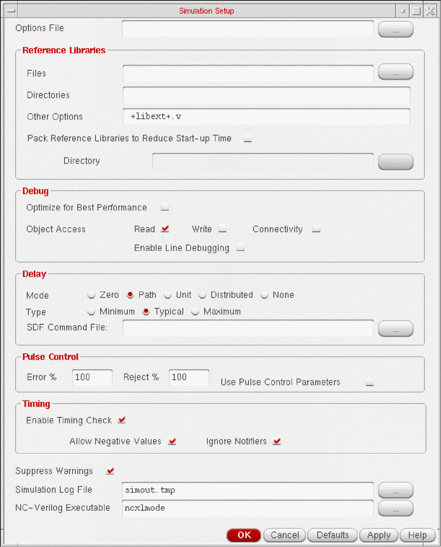
The following tables describe how to complete the Simulation Setup form by specifying the options listed below:
| Option | Description |
|---|---|
|
Sets the visibility access for all objects in the design. This is used to increase the simulation performance by not giving read, write or connectivity access to the simulation objects. By default this button is disabled. |
|
|
Specifies the read, write and connectivity access of the simulation object. The default value is read only access. For information, refer to Object Access Options |
|
|
It set to use line breakpoints and single stepping. If this option is not set, line breakpoints and single stepping would still not be available even when you select read, write and connectivity access. |
Object Access Options
The following table describes the access rights for the Object Access option:
Simulation Compare
Selecting this option displays the Simulation Comparison Setup form.
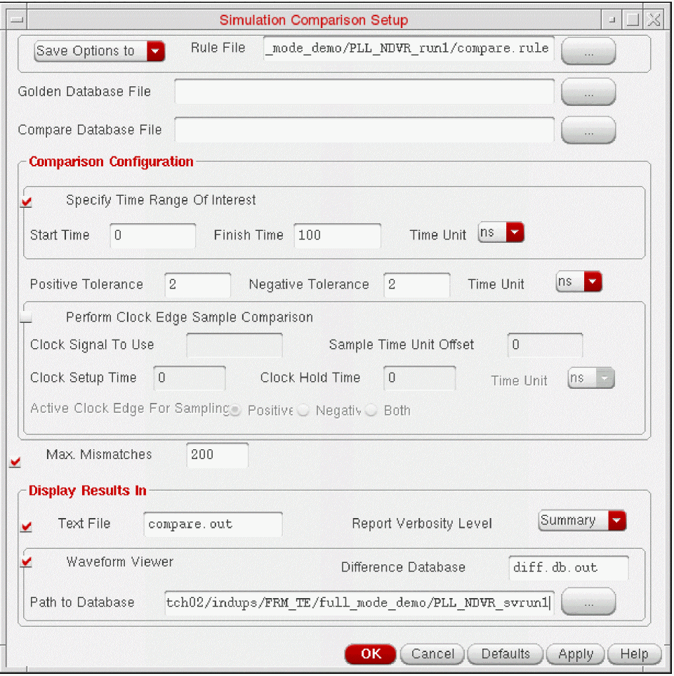
The following tables describe the various form options:
| Option | Description |
|---|---|
|
On selection, enables you to specify the time range that contains the signal events that you want to compare. Use absolute time values to define the range. For more information on its options, refer to Timing Options |
|
|
On selection, enables you to perform a clock edge sample comparison. For more information on its options, refer to Clock Edge Sampling Options |
|
|
When enabled (default), requires you to enter a number in the associated text field that specifies the number of mismatches that you want the system to find. The system stops the comparison when the specified limit is reached. When disabled, the system ignores the associated text field and continues the comparison regardless of the number of mismatches found. |
Cross Selection Setup
Selecting this option displays the Cross Selection Setup form.
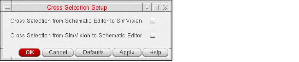
The following table describes the various form options:
Results Menu
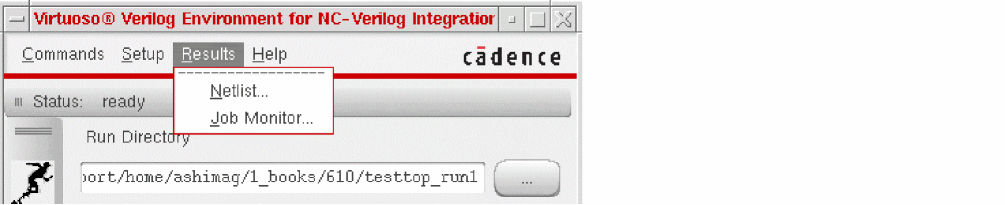
Netlist
Displays the netlist or a map file in a view window. The netlist file contains the Verilog text description of your design. A map file describes how the system maps names between Cadence® Verilog and the Design Framework II environment. When you netlist your design, the netlister generates a netlist and a map file. This command opens the View Netlist Run Files form that you use to specify the type of file and the name of the file you want to view.
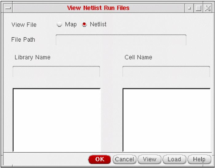
The following table describes the various form options:
Job Monitor
Displays the Analysis Job Monitor window, which you can use to select options that control batch jobs or to view information about batch jobs.
Analysis Job Monitor Window
On selecting Job Monitor option, the Analysis Job Monitor window appears. The window displays the following:
- The status of any batch job you started during this session
- Option buttons that let you control the simulation
- Selection buttons that you use to specify individual batch jobs
-
Information about a batch job and the progress of a batch simulation
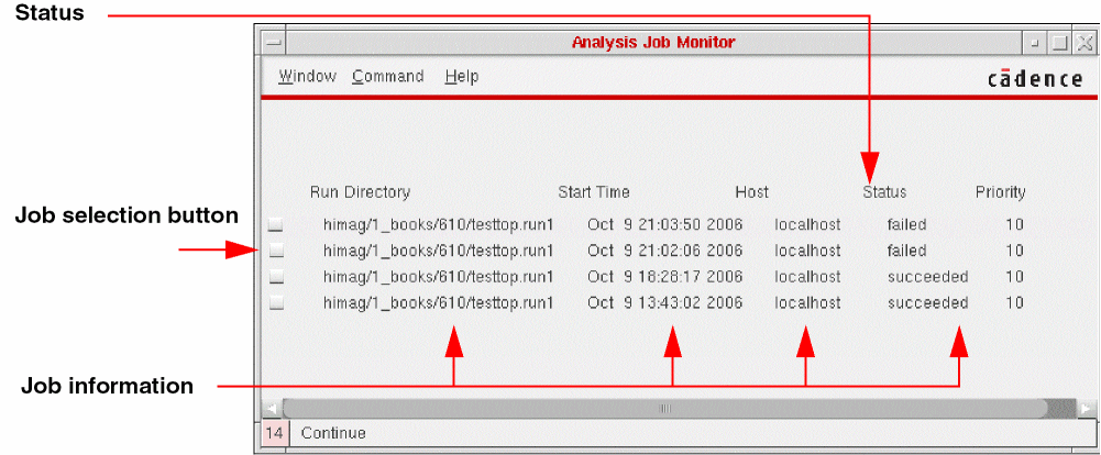
The Analysis Job Monitor form lists all batch simulations started during the current session.
- Run Directory specifies the run directory where the batch simulation is running.
- Start Time specifies the date and time the batch simulation was started.
- Host specifies the name of the host where the simulation is running.
-
Status specifies the status of the batch simulation. The status of a batch job can be
running,suspended,succeeded,killed, orfailed. - Priority specifies the order in which a batch job is processed.
Using Job Monitor
The option buttons at the top of the window let you control batch simulations. To apply an option to a batch job, click the job selection button for a batch job and then click an option button.
-
Show Run Log opens a view window that displays the simulation interface log file,
si.log, for the selected job. -
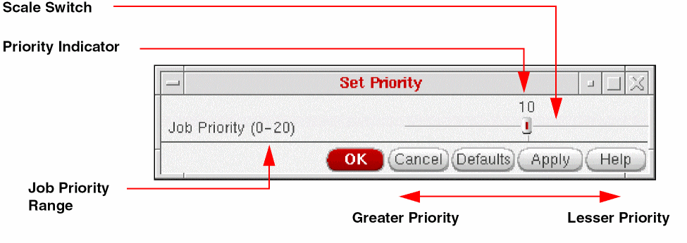
Set Priority displays the Set Priority form. You can use the Set Priority form to specify the priority of the selected job by dragging the scale switch left or right. The number above the scale switch changes as you drag the scale. A larger number indicates a lesser priority. When you decrease the priority of a particular batch job, the system can process jobs with higher priorities faster.
-
Kill terminates the selected job, whether it is running or suspended, and sets the batch status to
kill.A dialog box requests confirmation that you want to terminate the job. -
Suspend stops the selected job and sets the batch status to
suspended.You can resume a suspended job by clicking the Continue button. -
Continue resumes a job you suspended by clicking
Suspend. - Remove Entry deletes the selected job from the Analysis Job Monitor window but does not terminate or suspend it. A dialog box prompts you for confirmation that you want to delete the job from the window.
Help Menu
The Help menu lets you access help on using NC-Verilog Integration Environment. You can also access online support and resources from this menu.
Fixed Menu
This section describes each fixed menu command. Until you start an interactive simulation, Start Interactive is the only fixed menu command you can access.
Customizing Command Form Options
The default option settings for the NC-Verilog forms are set by the system when you enter an empty run directory. The initial settings are supplied with the software. When you edit the default settings on a form, the system saves the new settings to the .vlogifrc file. The .vlogifrc file settings override the default setup options supplied with the NC-Verilog software or supplied by a user in an .simrc file.
The .vlogifrc file is rewritten whenever you complete one of the following actions:
- Exit the run directory
- Choose the File - Quit command from the AEncv window
- Change to a new run directory
In general, you can customize some of the options for each of the following forms:
- SDF Delay Annotation Setup
- Netlist Setup
- Record Signals Setup
- Simulation Setup
- Simulation Comparison Setup
- Cross Selection Setup
For more information, refer to Appendix A, “Customizing Your Environment”.
Return to top