MarkNet Options Form
Use the Mark Net command lets you visually trace the physical connectivity of a net(s) in a layout design without having to use a schematic. The command extracts the metal, via, poly and diffusion layer information from the technology file and highlights these in the layout as the net passes from one layer to the next through the hierarchy.
The form comprises the following tabs:
|
Tab
|
Description
|
|
Options Tab
|
Provides options to specify hierarchy, region and highlight color.
|
|
Via Layers Tab
|
Defines via layers in the (layer1 viaLayer layer2) format, where each component layer can be specified as an LPP. If the Customized Via Layers check box on the Options Tab is not selected, the Via Layers tab is disabled and the via layers defined in the technology file are used.
|
|
Connected Layers Tab
|
Defines connected layers in the (layer1 purpose) (layer2 purpose) format. The connected layers map to the equivalent layers defined in the technology file. If the Customized Connected Layers check box is not selected on the Options Tab, the Connected Layers tab is disabled and connected layers are not used for tracing.
|
|
Stop Layers Tab
|
Defines the layers on which the Mark Net command must stop tracing a net. The stop criterion is specified in the layer stopLayer format, where both layers can be specified as LPPs. The Mark Net command stops tracing the connected shapes on the layer LPP if it finds an overlapping shape on the stopLayer LPP. If the Enable Stop Layers check box is not selected on the Options tab, the Stop Layers tab is disabled and the Mark Net command highlights all the connected shapes.
|
Options Tab
The following table describes the fields available on the Options tab of the Mark Net Options form:
|
Field
|
Description
|
|
Hierarchy Range
|
Sets how many levels of the hierarchy are highlighted when a net is selected.
-
Top to bottom: Highlights the selected net through the entire hierarchy of the window cellview.
-
Current to bottom: Highlights the net from the current edit cellview level to the bottom of the hierarchy.
-
Top to current: Highlights the net from the window cellview to the current edit cellview level.
-
Top to stop level: Highlights the net from the window cellview to the stop level specified in the Display Levels fields in the Display Options Form.
-
Current to stop level: Highlights the net from the current edit cellview level to the stop level specified in the Display Levels Stop field in the Display Options form.
-
User defined: Highlights the net through the user defined levels of hierarchy starting from the window cellview. This option makes the Start and Stop fields editable.
Environment variable: markNetRange
|
|
Start
|
Sets the hierarchy level at which the highlighting starts. This field is editable only when Mark Net Hierarchy Range is set to User defined.
Environment variable: markNetStartLevel
|
|
Stop
|
Sets the level at which the highlighting stops. This field is editable only when Mark Net Hierarchy Range is set to User defined.
Environment variable: markNetStopLevel
|
|
Region
|
-
Entire CellView: Traces nets in the entire cellview. This option is selected by default.
-
Viewing Area: Traces nets in the portion of the cellview that is displayed in the canvas at that instant.
-
Draw a Rectangle Region on the Canvas or Draw a Polygon Region on the Canvas: Enables you to specify a rectangular or polygonal area for tracing nets. Select the required option, and then click in the canvas to specify the vertices of the rectangle or polygon.
|
|
Auto Highlight Color
|
Marks up to ten nets with a different color by automatically cycling through Cadence-defined layer purpose pairs y0 drawing through y9 drawing. If the appearance of these layer purpose pairs is not what you want, you can change them using the Display Resource Editor.
Environment variable: markNetAutoColorCycle
|
|
Highlight Color
|
Enables you to manually change the color used to highlight the nets. You can select one of the Cadence-defined layer purpose pair y0 drawing through y9 drawing. If the appearance of these layer purpose pairs is not what you want, you can change them using the Display Resource Editor.
|
|
Thick Line
|
Enables you to display the traced nets in bold.
Environment variable: markNetThickline
|
|
Highlight Incrementally
|
Displays the traced connectivity in a progressive manner. When this check box is selected, the connectivity is highlighted after processing every 10,000 shapes.
|
|
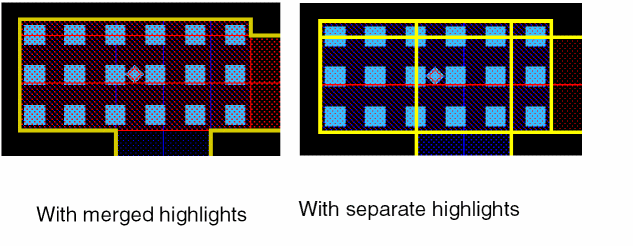
Highlight Individual Shapes
|
Adds a separate highlight for each shape.
|
|
Retain Via Info for Save MarkNets
|
Enables you to save via shapes when you later run the Connectivity – Nets – Save All Mark Nets command. The via shapes are retained in the cellview created for storing the traced shapes. This option is not selected by default. Therefore, by default, the via shapes are not included in the separate cellview generated by the Save All Mark Nets command.
The “Number of shapes processed by Mark Net”, as reported in the CIW, is not impacted by this check box setting.
Environment variable: markNetSaveViaInfo
|
|
Select From Overlaps
|
Enables you to select the LPP from where the Mark Net command starts tracing the net when multiple overlapping shapes are selected. If this check box is selected, clicking overlapping shapes opens the Choose LPP to Mark form in which you can select the required LPP. If the check box is not selected, the Mark Net command starts tracing the net from any one of the overlapping shapes.
Environment variable: markNetSelectOverlapLayer
|
|
Customized Connected Layers, Customized Via Layers, and Enable Stop Layers
|
Enables the settings defined on the Via Layers, Connected Layers, and Stop Layers tabs to be used for tracing a net. These check boxes are selected by default. If the Customized Via Layers check box is not selected, the via layers defined in the technology are used. If the Customized Connected Layers or the Enable Stop Layers check box is not selected, the connected layers or stop layers are not used.
Environment variables: markNetViaLayer, markNetConnectedLayer, markNetStopLayer
|
|
Exclude Purposes
|
Enables you to exclude the specified purposes from tracing. The default purpose values that are listed are annotate, boundary, error, flight, label, and warning. You can delete any of the default purpose values. This check box is selected by default.
Environment variable: markNetExcludePurposes
|
|
Save/Load custom settings for Via, Connected and Stop Layers
|
-
Browse: Opens the UNIX Browser window. Use this window to specify the name and location of the file to which you want to save the layer settings. You can also use this window to locate an existing file containing customized layer settings. The path and file name that you specify are displayed in the Browse field. If a markNetOptions file has been specified using the markNetOptionsFile environment variable, the settings for the via, connected, and stop layers are read from this file at the start of a new Virtuoso session.
-
Save To: Saves the layer settings to the file specified in the Browse field.
-
Load From: Populates the Via Layers, Connected Layers, and Stop Layers tabs with the layer settings stored in the file specified in the Browse field.
-
Via Layers: Enables you to save or load via layer settings to or from the file specified in the Browse field.
-
Connected Layers: Enables you to save or load connected layer settings to or from the file specified in the Browse field.
-
Stop Layers: Enables you to save or load via layer settings to or from the file specified in the Browse field.
-
Exclude Purposes: Enables you to save or load exclude purposes settings to or from the file specified in the Browse field.
By default, settings for all the three layers — via, connected, and stop — are saved and loaded to or from the file specified in the Browse field.
|
Via Layers Tab
The following table describes the fields available on the Via Layers tab of the Mark Net Options form:
|
Field
|
Description
|
|
Via Layers list box
|
Displays all via layers — those defined by you and ones that have been picked from the technology file.
-
Enable: Lets you select the via layers that you want to use for tracing a net. To select all the via layers, select the check box at the top of the column. To select individual via layers, select the check box against each required via layer.
-
Delete: Lets you delete via layers that are invalid or not required. To delete all the via layers, select the check box at the top of the column and click Delete. To delete individual via layers, select the check box against a via layer and click Delete.
|
|
Add Via Layers
|
Lets you define the via layers in the (layer1 viaLayer layer2) format. For each layer, specify the layer name in the layer column and the purpose name in the purpose column. It is optional to specify the purpose name.
|
|
Add
|
Displays the newly added via layer in the (layer1 viaLayer layer2) format in the Via Layers list box.
|
|
Reset to TechDB Defaults
|
Lets you use the via layers defined in the technology file. Clicking this button populates the list box with the via layers from the technology file and deletes any via layers that you may have added.
|
Connected Layers Tab
The following table describes the fields available on the Connected Layers tab of the Mark Net Options form:
|
Field
|
Description
|
|
Connected Layers list box
|
Displays all connected layers — those defined by you and ones that have been picked from the technology file.
-
Enable: Lets you select the connected layers that you want to use for tracing a net. To select all the connected layers, select the check box at the top of the column. To select individual connected layers, select the check box against each required connected layer.
-
Delete: Lets you delete connected layers that are invalid or not required. To delete all the connected layers, select the check box at the top of the column and click Delete. To delete individual connected layers, select the check box against a connected layer and click Delete.
|
|
Add More Entries
|
Displays a text field in the Connected Layers list box. In this field, you specify the values in the (layer1 purpose) (layer2 purpose) format.
|
|
Reset to TechDB Defaults
|
Lets you use the connected layers defined in the technology file. Clicking this button populates the list box with the connected layers from the technology file and deletes any connected layers that you may have added.
|
Stop Layers Tab
The following table describes the fields available on the Stop Layers tab of the Mark Net Options form:
|
Field
|
Description
|
|
layer [purpose] stopLayer [purpose] list box
|
Displays the stop layers that you have defined.
|
|
layer [purpose] [color] [lock] stopLayer [purpose] list box
|
Displays the stop layers that you have defined.
-
Enable: Lets you select the stop layers that you want to use for tracing a net. To select all the stop layers, select the check box at the top of the column. To select individual stop layers, select the check box against each required stop layer.
-
Delete: Lets you delete a stop layer that is invalid or not required. To delete all the stop layers, select the check box at the top of the column and click Delete. To delete individual stop layers, select the check box against a stop layer and click Delete.
|
|
Add Stop Layers
|
Enables you to define the stop layers in the (layer stopLayer) format. For each layer, specify the layer name in the layer column and the purpose name in the purpose column. The purpose name is optional. Appropriate messages are generated if you try to add duplicate entries for a stop layer or specify the same value for layer and stopLayer.
|
|
Add Stop Layers
|
Enables you to define the stop layers in the (layer stopLayer) format. For each layer, specify the layer name in the layer column, the purpose name in the purpose column, select the color (‘any’, ‘gray’, ‘mask1’ or ‘mask2’ ....’maskn’) in the color column, select the lock state ( ‘any’, ‘yes’, or ‘no’) in the lock column. The purpose name is optional. Appropriate messages are generated if you try to add duplicate entries for a stop layer or specify the same value for layer and stopLayer.
|
|
Add
|
Displays the newly added stop layer in the layer [purpose] stopLayer [purpose] list box.
|
Related Topics
Net Tracing Using the Mark Net Command
Tracing Nets
Return to top