Transmission Line Bend Styles
Transmission line bend styles can be of three types: standard bend, chamfer, and radial.
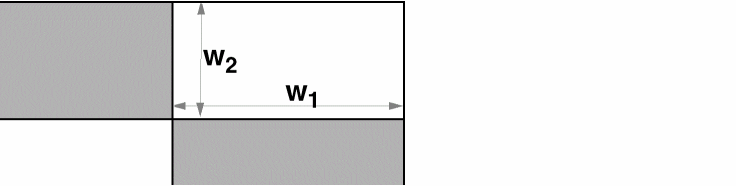
Standard Bends
The following illustration shows a standard bend. All angles in a standard bend are 90 degrees.
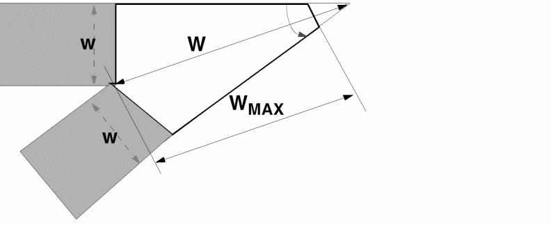
Bend Factor is the allowed ratio of the width (WMAX) of the bend for a given angle to the width (W0) of a 90-degree bend. If the width (W) of a bend is greater than WMAX, the bend is chamfered so that the width is decreased to WMAX. The effect of Bend Factor is shown in the following illustrations.
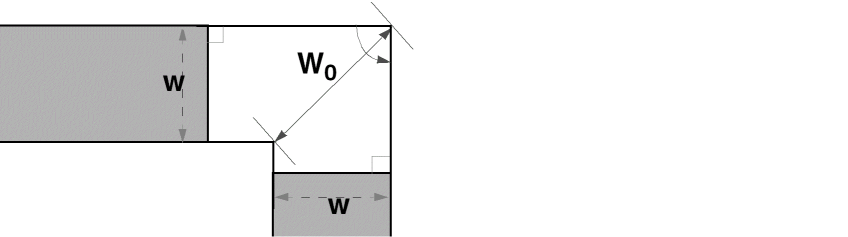
Specified value of bend factor defines WMAX in the following figure:
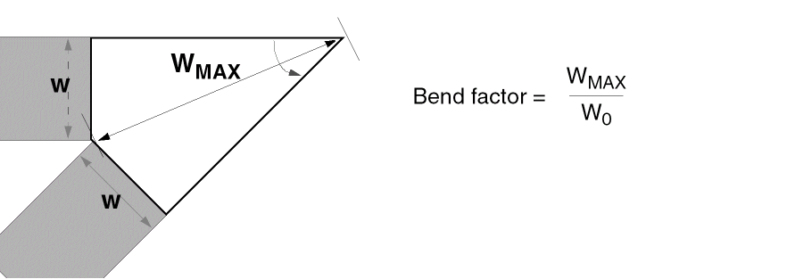
For W>WMAX, bend chamfered to decrease W to WMAX in the following figure:
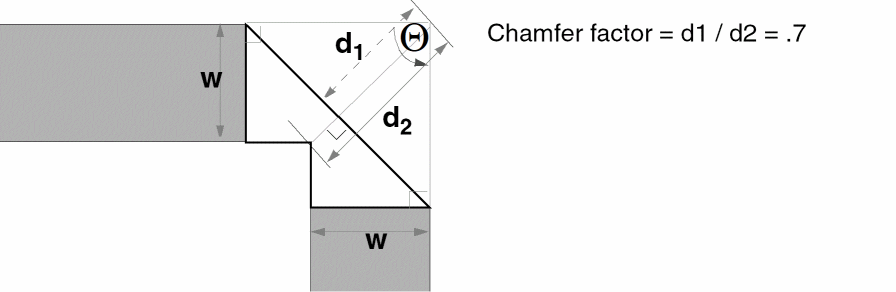
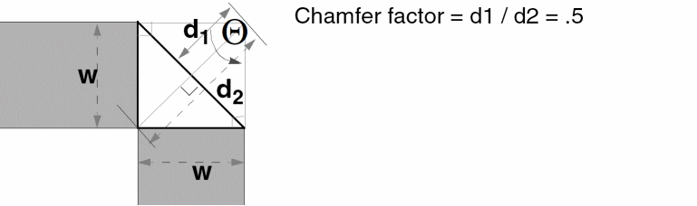
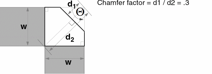
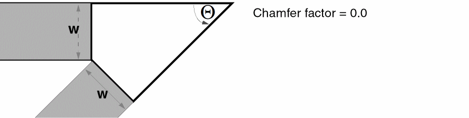
Chamfer Bends
The types of chamfer bends and the effect of Chamfer Factor are shown in the following illustrations. The appearance of the corner is determined by the value of the chamfer factor, d1/d2.
Example 1
Example 2
Example 3
Example 4
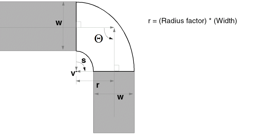
Radial Bends
A radial bend has a rounded corner determined by the Radius Factor. The Resolution is the number of segments in a 180-degree bend.
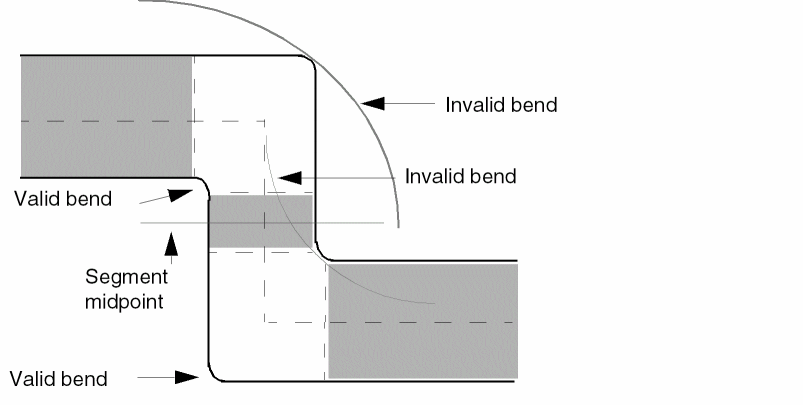
Bends must be properly formed. For example, segments adjacent to a bend must not be too short with respect to the bend. To prevent this, the layout editor does not allow a bend on adjacent segments to extend past the midpoint of the shortest adjacent segment.
In other words, the bend and the segment must coincide before or at the midpoint of the segment so that segments approaching the midpoint from opposite directions match at the midpoint. These segments must intersect the midpoint at 90 degrees. If necessary, the layout editor alters the bend to meet these conditions.
Related Topics
Creating Advanced Transmission Lines
Return to top