2
Getting Started with Voltus-Fi-XL
This section contains an overview of Voltus-Fi-XL, its key features, and how to start working with the tool.
Overview of Voltus-Fi-XL
Voltus-Fi-XL is used for transistor-level power-integrity analysis, which includes multi-mode simulation (MMSIM) electromigration and voltage drop (EMIR) analysis for transistor designs. The target designs include analog, analog/mixed-signal (AMS), and custom digital designs of large sizes that are created using Virtuoso.
This product is tightly integrated within Virtuoso. The results of the analyses are displayed on the Virtuoso layout. Voltus-Fi-XL also generates text reports of the analyses and lets you query the analyses results to view specific violations in the layout. This is used to identify and debug regions of high IR drop and EM violations in the design. After analyzing the EMIR results, you can create power-grid views (PGVs) of the design block, which can then be used in Voltus for mixed-signal analysis.
Voltus-Fi-XL uses the simulation database generated by simulators—Spectre Accelerated Parallel Simulator (APS) and Spectre eXtensive Partitioning Simulator (XPS)—as inputs to perform EMIR analysis.
A brief description of the capabilities of the two simulators is provided below.
- Spectre APS is a new-generation SPICE simulator that provides high performance, high capacity circuit simulation with full Spectre accuracy. APS achieves maximum simulation performance by enabling multi-threading on multi-core and multi-CPU shared memory systems.
- Spectre XPS is a new-generation transistor-level circuit simulator that emphasizes high simulation performance and large simulation capacity, and addresses the design and verification needs of full-chip low-power designs at advanced process nodes.
Related Topics
- Key Features of Voltus-Fi-XL
- Running Voltus-Fi-XL in Batch Mode
- Running Voltus-Fi-XL in GUI Mode
- Accessing Documentation and Help
Key Features of Voltus-Fi-XL
The following table lists the key features of Voltus-Fi-XL.
Installation Information
- Voltus-Fi-XL is launched within the Virtuoso Platform. To use this product, you must have the Virtuoso ICADVM20.1 release version.
-
To check whether Voltus-Fi-XL is available in your Virtuoso Studio Design Environment, type the following in the UNIX window, shell, or xterm:
vfibatch -v
This prints the product version available in your Virtuoso Studio Design Environment. -
Voltus-Fi-XL is supported only on the Linux (only 64-bit) platform. To specify the 64-bit version, you need to set the
CDS_AUTO_64BITenvironment variable before starting the software. If you are using thelnx86operating system, verify that it supports 64-bit applications.
Related Topics
Running Voltus-Fi-XL in Batch Mode
You can run Voltus-Fi-XL as a batch command, running it from Virtuoso in non-graph mode. Batch mode is used when the simulation database is already generated, and you want to print the IR/EM text reports without viewing the plots on the layout.
The batch mode flow of Voltus-Fi-XL supports both the configuration file or the conf file and the command file, cmd_file.
To run Voltus-Fi-XL in batch mode, do one of the following:
-
Use the following command to run Voltus-Fi-XL from the UNIX window, shell, or xterm:
vfibatch –cmd <cmd_file>
Where, <cmd_file> is a file with a list of batch commands that define the input data, control the execution of the analysis, and specify the output location. -
Use the following command to run Voltus-Fi-XL by specifying the EMIR configuration file:
vfibatch -c<emir conf>-db<simulation directory path>-outdir
<output directory>
You can specify the control file options in the configuration file using theemirutilcommand.
Related Topics
Running Voltus-Fi-XL in GUI Mode
The flow to run Voltus-Fi-XL in GUI mode comprises the following steps:
- Starting the Virtuoso Studio Design Environment
- Opening the Schematic or Layout View
- Launching Voltus-Fi-XL
Starting the Virtuoso Studio Design Environment
To start the Virtuoso Studio design environment, do the following:
-
Type
virtuoso &in the UNIX window, shell, or xterm.
The Command Interpreter Window (CIW) opens. You interact with the design environment from the CIW.
Opening the Schematic or Layout View
You need to open the schematic or layout view of your design in the Virtuoso Schematic Editor or Virtuoso Layout Suite, respectively. To do this, use either the File menu or the Tools menu of the CIW.
-
Choose File – Open.
The Open File form is displayed. -
In the File group box, select a Library, select a cell name from the Cells list or directly type the cell name in the Cell field, and select a View (either schematic or layout).
Alternatively, you can click Browse to open the Library Browser – Open File window and select your design. - In the Application group box, select an item from the Open with drop-down list.
- Select one of the Open for options: edit or read.
- Click OK.
-
Choose Tools – Library Manager.
The Library Manager form is displayed. - To select a library and its corresponding cell and view, click the item names in the order: Library, Cell, and View. Select schematic or layout in the View section.
- Double-click the view to open the design in the Virtuoso Schematic Editor or Virtuoso Layout Suite.
Launching Voltus-Fi-XL
You can run Voltus-Fi-XL from the Virtuoso Studio Design Environment in two ways. You can run it either from the Virtuoso Layout Suite using the plug-in option, or from the Virtuoso Analog Design Environment (ADE L/ADE XL) after adding the DSPF file and performing postlayout simulation with EMIR analysis.
The steps for launching Voltus-Fi-XL using ADE L are detailed below. The same steps can be used to launch Voltus-Fi-XL using ADE XL.
-
From Virtuoso Schematic Editor or Virtuoso Layout Suite, choose Launch – ADE L.
The ADE L window opens. - Set up and run simulation, and generate the simulation database.
- In the main menu of the ADE L window, choose Results – EM/IR Data – Layout Analysis.
-
In the Select Layout View form, select the cell name from the Cell drop-down list and click OK.
The following windows open:
Related Topics
- Running Voltus-Fi-XL in Batch Mode
- Batch Commands in Voltus-Fi-XL
- Voltus-Fi-XL Console Description
- Launching Voltus-Fi-XL from Virtuoso ADE Explorer Environment (video)
- Launching Voltus-Fi-L/XL from Virtuoso Layout Suite for EMIR Analysis (video)
Specifying Simulation Settings in ADE L/ADE XL
Before you run simulation, you need to specify the simulation settings in ADE L/ADE XL. The steps required in ADE L are detailed below. The same steps can be used in ADE XL.
To specify simulation settings in ADE L, do the following:
- In the main menu of the ADE L window, choose Setup – Simulation/Directory/Host and specify the Simulator as spectre.
- Choose Setup – High Performance Simulation and ensure that APS and its Post-Layout Settings group box options are selected.
- Choose Setup – Model Libraries and load the appropriate model files.
-
Choose Setup – Simulation Files and in the Simulation Files Setup form, specify the Definition Files and Parasitic Files (DSPF).
Related Topics
- Running Voltus-Fi-XL in GUI Mode
- Specifying EMIR Analysis Settings in ADE L/ADE XL
- Generating Simulation Database in ADE L/ADE XL
Specifying EMIR Analysis Settings in ADE L/ADE XL
Before performing EMIR analysis in Voltus-Fi-XL, you need to specify the EMIR analysis settings in ADE L/ADE XL. The settings required for static and dynamic EMIR analysis are different. The steps required in ADE L are detailed below. The same steps can be used in ADE XL.
Setting up Static EMIR Analysis
Static EMIR analysis estimates the IR and EM current density without performing a circuit simulation based on the user-specified current estimates in the static current file. To set up static EMIR analysis, do the following:
-
In the main menu of the ADE L window, choose Setup – EM/IR Analysis.
The Voltus-Fi XL Analysis Setup form opens. - In the Analysis tab, select the Type of analysis as Static.
- In the Net Selection group box, click Select to choose the Net Name for the nets to be analyzed in the schematic. In the schematic, select an instance. Selecting an instance chooses all the nets of the instance with the wild card “*”.
- Specify the Static Current File.
-
Select avg current analysis for both IR Drop Analysis and EM Current Analysis.
- Click Add/Modify to add the net and analysis combination statements to the summary information in the EMIR configuration file.
- In the Solver tab, ensure that the Speed is set to default.
-
In the Option tab, select an option from the Advanced Option drop-down list or specify the required option in the Additional Option field.
- Click Run to invoke the spfchecker.
- Select the EMIR Analysis for Static check box at the bottom of the form.
- Click OK to save the static EMIR analysis settings for the run.
Setting up Dynamic EMIR Analysis
Dynamic EMIR analysis requires a DC or transient simulation. To set up dynamic EMIR analysis, do the following:
-
In the main menu of the ADE L window, choose Setup – EM/IR Analysis.
The Voltus-Fi XL Analysis Setup form opens. - In the Analysis tab, select the Type of analysis as Dynamic.
- In the Net Selection group box, click Select to choose the Net Name for the nets to be analyzed in the schematic. In the schematic, select an instance. Selecting an instance chooses all the nets of the instance with the wild card “*”.
-
Select the analysis types from available options: IR Drop Analysis, EM Current Analysis, and Advanced IR Drop Analysis.
- Click Add/Modify to add the net and analysis combination statements to the summary information in the EMIR configuration file.
- In the EM Rule Check Setup group box, specify the EM Tech File.
- In the Solver tab, select direct as the Solver Method.
-
In the Time Window Setup group box, select an option to specify EMIR analysis duration.
Full Transient is selected by default, which means the EMIR analysis is run over the entire simulation period. You can also select Time Window and provide the start and stop times. -
In the Option tab, select an option from the Advanced Option drop-down list or specify the required option in the Additional Option field.
- Click Run to invoke the spfchecker.
- Select the Enable EMIR Analysis in Transient or DC Simulation check box at the bottom of the form.
- Click OK to save the dynamic EMIR analysis settings for the run.
The Summary Information group box at the bottom of the Voltus-Fi XL Analysis Setup form is updated as you make changes in the form or click Add/Modify where applicable. The summary section contains the final set of commands in the EMIR configuration file. This file is later used by Spectre APS for performing EMIR analysis.
Related Topics
- Performing Static EMIR Analysis in the Virtuoso ADE Explorer Environment (video)
- Setting Up and Running Dynamic EMIR Analysis in Virtuoso ADE Explorer (video)
- Running Voltus-Fi-XL in GUI Mode
- Specifying Simulation Settings in ADE L/ADE XL
- Generating Simulation Database in ADE L/ADE XL
Generating Simulation Database in ADE L/ADE XL
After specifying simulation and EMIR analysis settings, you need to run a simulation in ADE L/ADE XL to generate the simulation database.
-
In the main menu of the ADE L/ADE XL window, choose Simulation – Netlist and Run.
You should use this option when you run the simulation for the first time and also when you have edited your design. Using this option ensures that your design, the ADE setup, and the output netlist for simulation are synchronized. A progress bar appears at the bottom of the simulation window displaying the status of netlisting and simulation runs. You can view the details of the run in the UNIX window, shell, or xterm.
Related Topics
- Running Voltus-Fi-XL in GUI Mode
- Specifying Simulation Settings in ADE L/ADE XL
- Specifying EMIR Analysis Settings in ADE L/ADE XL
Accessing Documentation and Help
You can access the Voltus-Fi-XL documentation and Cadence Help using one of the following methods:
- Change to the following directory: installation_dir/tools/bin
-
Enter the following command:
./cdnshelp
After launching Cadence Help, pressF1or choose Help – Contents to display the help page for Cadence Help.
- Click Help in the Voltus-Fi-XL console.
-
Click Help on the bottom-right corner of any form.
Clicking Help opens the Voltus-Fi-XL user guide entry for the form in the Cadence Help window.
-
Select Cadence Online Support on the Virtuoso Help menu.
The Cadence Online Support website is opened in your browser. You are required to have a Cadence Online Support account to access these materials.
Related Topic
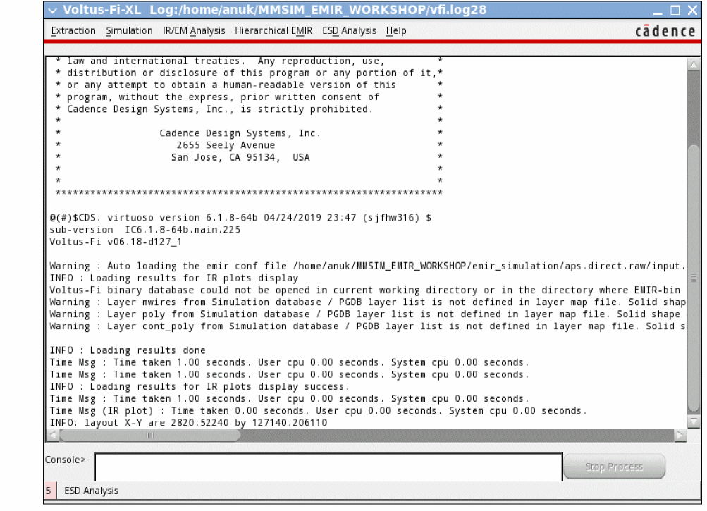
Voltus-Fi-XL Console Description
The following main menus of Voltus-Fi-XL are available. In addition to the menus, there is a Stop Process button in the console. This button is enabled when you run a process. Click this button to stop a process while it is running.
Related Topics
Return to top