11
Supporting Width Spacing Patterns
Wire editing has been enhanced to support snap pattern definitions called widthSpacingSnapPatternDefs. The width spacing pattern (WSP) definitions used with widthSpacingSnapPatternDef are stored either in the technology database or the design database. When a width spacing snap pattern definition is enabled as a global grid through a snapGridVertical or snapGridHorizontal constraint, global WSP-based editing is supported in wire editor. In addition, wire editing allows individual regions in a cellview to use different WSPs instead of the global grid. To create a region, see widthSpacingSnapPatternDef defined in a region need not be used as a global grid in the cellview.
Furthermore, wire editing allows multiple width spacing snap pattern definitions to share the same LPP. This means that an LPP of a region does not directly identify a unique width spacing snap pattern definition. Therefore, a new string attribute can be associated with a region to determine the width spacing snap pattern definition with which it is associated. To set the widthSpacingSnapPatternDef to be used for a region, see
This chapter describes the following width spacing pattern features.
- Width Spacing Pattern Display in Wire Editing
- allowedWireTypes Support
- Snapping Behavior in WSP During Wire Editing
- Working with Width Spacing Patterns During Wire Editing
- Automatic Switching of the Active Pattern Across Regions
- Working with Selected Sets of Wires
- Nested WSP Regions
- Supporting pathSegs with Different WSPs across Regions
- Wire Editor Hierarchy Support
- Pattern Flipping Support
Width Spacing Pattern Display in Wire Editing
When using width spacing patterns, it is essential that you are able to visualize the available tracks and their respective widths in the canvas. Therefore, the following display enhancements have been made available for WSP.
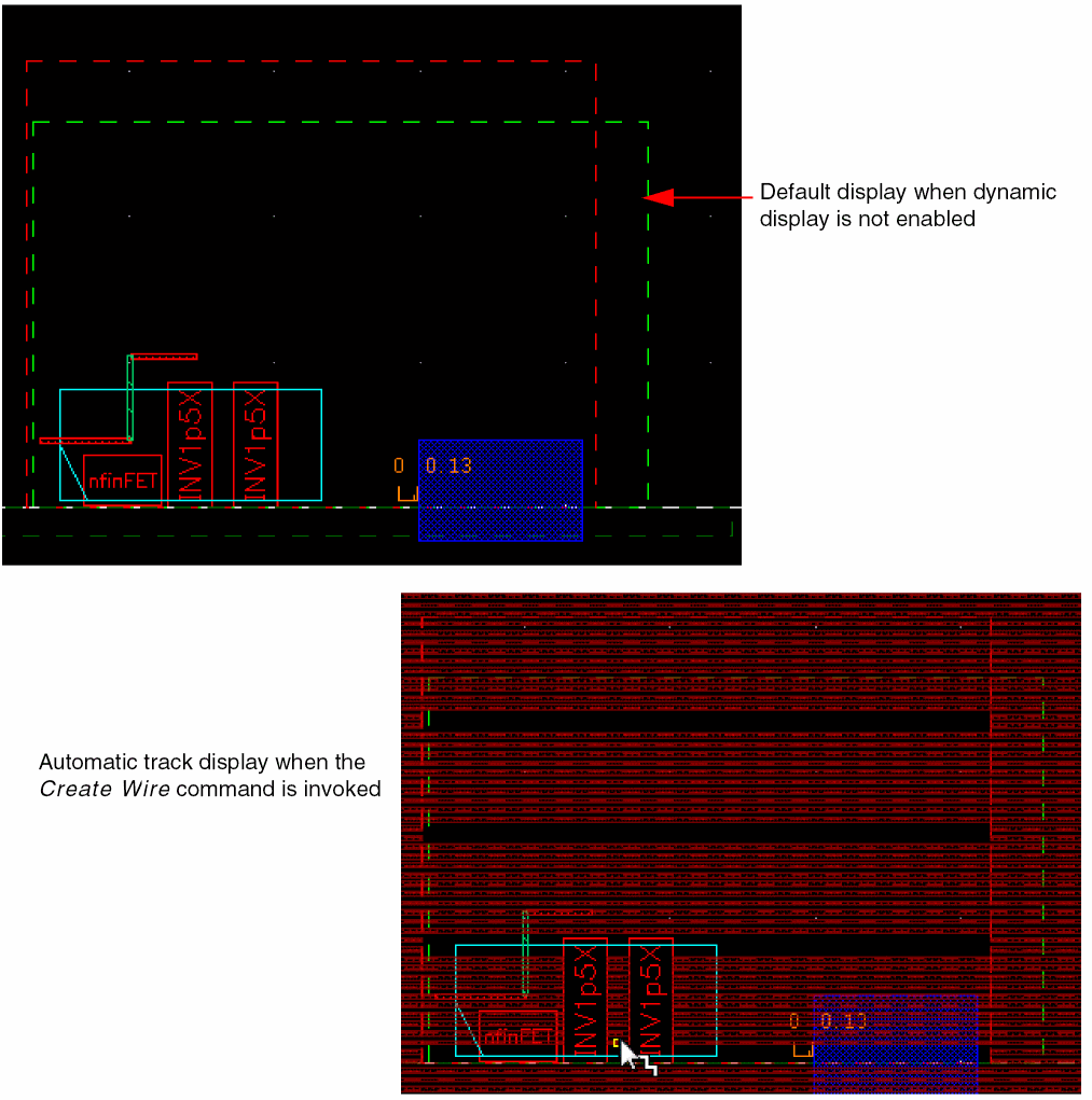
Dynamic Display
Dynamic display is visible in wire editing only when the Snap Pattern option is selected from the Wires drop-down list in the Layout Editor Options form and the reference object is snapable to the WSP grid. The dynamic display feature facilitates the display of accessible or valid tracks. This feature displays the tracks based on the current layer-purpose pair, active pattern, minWidth constraints, wireType constraints, and regions. The dynamic display also displays the valid tracks of upper and lower layers.
During wire creation and editing, the active pattern in the applicable WSP track is displayed in the design automatically as soon as the Create Wire command is invoked. While creating a wire, the corresponding WSP grid for the selected layer is displayed, even if the visibility of the grid is turned off in the Grids panel of the Palette assistant.
The following figure shows the display of tracks when the Create Wire command is invoked.
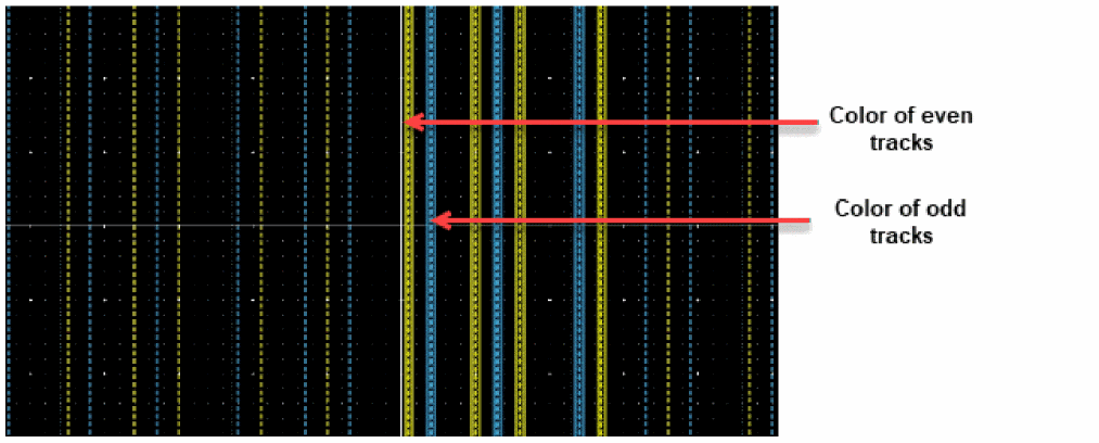
Dynamic Display for Colored snapPatternDef Tracks
During wire creation, for snapPattern the even and odd tracks are displayed in alternate colors based on the packets defined in the display resource (.drf) file. The track immediately to the right of the anchor point gets the regular packet. The track after that gets the override packet.
Alpha Blending
During wire creation and editing, there is a transparent display of the current track and upper and lower layer tracks in the design as soon as a layer is selected in the Layers panel of the Palette assistant and the Create Wire command is invoked. This is known as alpha blending. This feature helps you to visualize the layer on which a wire is being created. The following figure shows the alpha blending display when the Metal2 layer is selected in the Layers panel of the Palette assistant and the Create Wire command is invoked.
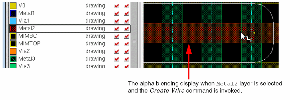
The transparency at different levels for the track fill or the track outline, is controlled by several environment variables. For more information about the alpha blending environment variables, see
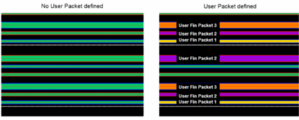
Customizing Display of WSP Tracks
To visually differentiate and easily identify some WSP tracks, you can now customize stipple patterns. You can define a display packet and attach it to a WSP track. The following figure shows WSPs when a display packet is defined for a WSP track and when it is undefined (and a default display packet is used).
For more information, see widthSpacingPatterns in the Virtuoso Technology Data ASCII Files Reference. Also, see techCreateWidthSpacingPattern and techCreateWidthSpacingPatternWithColor, and wspCreateWSP SKILL APIs.
allowedWireTypes Support
The wire editing supports the new allowedWireTypes constraint. When the allowedWireTypes constraint is set on a net in a design, then wire editing on that net conforms to the constraint rules and only shows and snaps to the tracks whose wireType matches the value of the constraint.
Snapping Behavior in WSP During Wire Editing
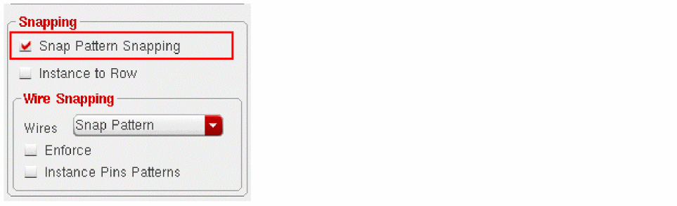
Enabling Wire Snapping
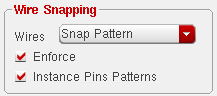
To enable snapping of wires, you can specify the Wire Snapping options in the Layout Editor Options form.
- Choose Options – Editor.
-
In the Layout Editor Options form, the Snap Pattern Snapping option is selected by default. Select the Snap Pattern option from the Wires drop-down list in the Wire Snapping group box. When the Snap Pattern option is selected, the Enforce and Instance Pins Patterns check boxes are automatically enabled.
-
Select the Enforce check box if you want the wire to inherit the width and the direction of the active WSP pattern. When the Enforce check box is selected, the wire is snapped to the centerline of the track pattern. Also, the wire inherits the width of the active WSP pattern and the direction in which the wire is created is the same as the direction of the track pattern. By default, the Enforce check box is selected.
However, if the Enforce check box is deselected, while the wire is snapped to the centerline of the track pattern, the width of the wire is the default width and there is no restriction on the direction in which the wire is snapped.The Enforce check box is only enabled when the Wires option is either set to Track Pattern or Snap Pattern.Also, the width associated with a WSP track can be set to0. Wire Editor supports the track that has0width. The track with0width is similar to the trackPattern use model; where any wire width can be used for a track. In addition, you can press theCtrl+Shiftkey and scroll the mouse wheel up or down to dynamically change the width of a wire. - To view the patterns that are available in an instance, select the Instance Pin Patterns check box. When this option is selected, you can view the active pattern of the instance. However, if this option is deselected, the active pattern of the top level is visible even in the instance.
Snapping of Wire in Width Spacing Patterns
During wire creation, the valid track patterns of a layer are displayed. Also, only the tracks corresponding to the current layer and a layer above or below it are shown.
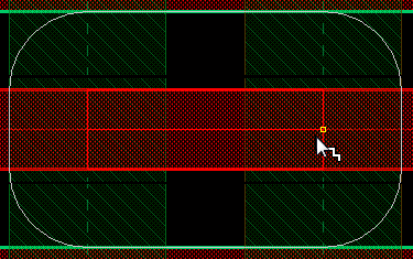
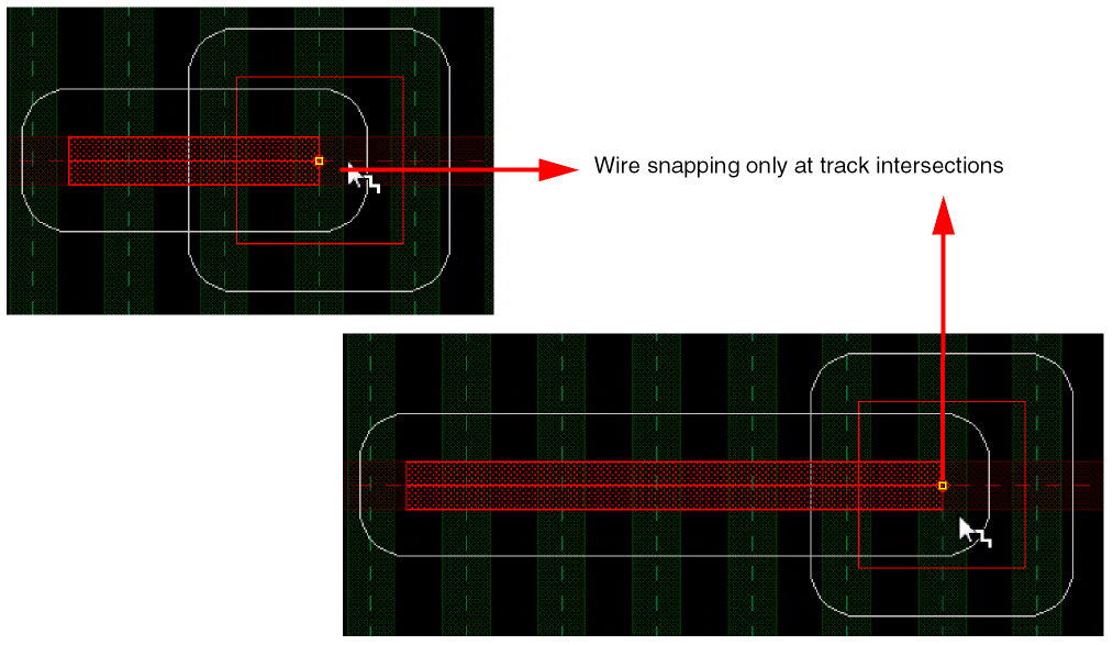
When a wire is created on a metal layer, the track magnet automatically pulls the wire towards the track intersection and the wire is snapped to the nearest track of the active pattern. In addition, the created wire inherits the width and direction of the track to which it is snapped, as shown in the following figure.
Also, while snapping, the Create Wire command follows the tracks and lets you create a jog by remaining in the same metal layer even if there are only horizontal tracks on a metal layer and vice versa. The wire is created as a Z-shape, where the first and last pathSeg are in the preferred routing direction and the middle pathSeg is in the non-preferred routing direction. This is only possible when the weEnforceDirFromRoutingPattern variable is set to nil. However, the automatic via insertion is disabled when the environment variable weEnforceDirFromRoutingPattern is set to nil. In addition, a via can be created only in the preferred direction and not in the non-preferred direction.
While creating a wire on a defined region, the wire is snapped to the closest strip lines on the routing direction. The high-level steps that are followed for snapping a wire to the width spacing patterns are listed below:
- Specify the width spacing pattern definition defined in the ASCII technology file.
- Specify the name of the layer, typically the Active layer, on which a wire will snap.
- Create a wire.
Also, while creating a wire, orthogonal WSP grid constraint defined in the technology file automatically adjusts the wire with a truncate extension value so that the begins and ends points of a wire are on the grids. The snapping points that are applicable to both upper and lower are visible as dots, as shown in the following figure.
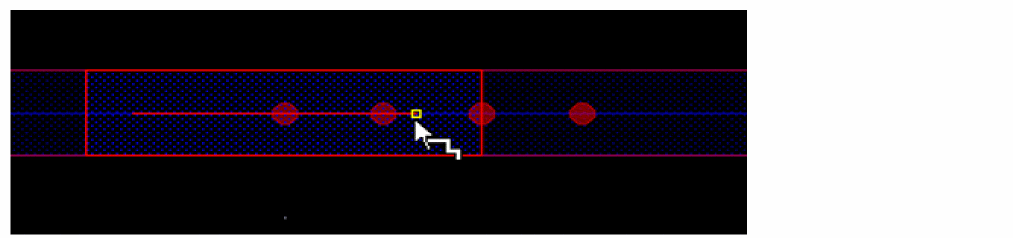
However, when the snapping points are either applicable to lower or upper, then the orthogonalWSPGrid is represented by a small triangle, as shown in the following figure,
In addition, the via enclosure of intermediate layers extend to align to the grid defined by orthogonalWSPGrid.
spacings(
(orthogonalWSPGrid "M2" "M1WSP")
) ; spacing
In the above example, a wire is created On M1 layer and a stack via up to M3 is added. The via enclosure on M2 is extended to align the WSP grid on M1.
Now, you can define orthogonalWSPGrid constraint in the local region which is different from the one that is defined in the global region.
WSSPDef, it requires that the primary layer has a standard routing WSSPDef selected as well.
The orthogonalWSPGrid constraint in the local region overrides the orthogonalWSPGrid constraint defined in the global region.
When the local end grid of a region differs from the local end grid of the global region, the wire snaps to the orthogonal grid near the boundary instead of the boundary of the region. This implies that the yellow cursor is not allowed to be placed near the boundary.
Support for snapPattern singleTrackCenter
To support the enhanced snapping behavior, a specific attribute singleTrackCenter is added to snapPatternDefs in the technology file.
layerRules(
snapPatternDefs(
(t_name (tx_layer tx_purpose)
['snappingLayers
(
         …
   'snappingMode "singleTrackCenter"
…
)
]
)
) ;snapPatternDefs
) ;layerRules
Some scenarios supported for this enhancement are as follows:
Changing Width and Snapping
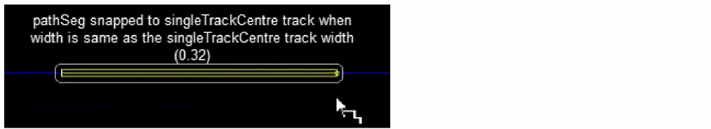
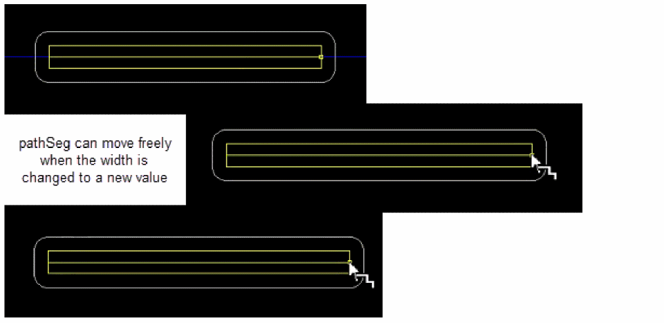
When you start creating a pathSeg and the width of the pathSeg is same as the singleTrackCenter track width, the pathSeg is automatically snapped to the singleTrackCenter track and only singleTrackCenter track is displayed.
However, if the pathSeg is on a singleTrackCenter track and the width of the pathSeg is changed to a new value, the width of the pathSeg is changed and the mouse cursor moves freely in the design.
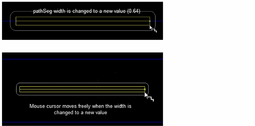
In case, the pathSeg is not on a singleTrackCenter track, the width of the pathSeg cannot be changed to a singleTrackCenter track width and a warning message is displayed in CIW.
Sliding a pathSeg
Use the width before sliding to determine if the wire needs to be snapped to the singleTrackCenter track. If the width before sliding is the same as the singleTrackCenter track width, the wire can only be moved to the singleTrackCenter track. Otherwise, it can be snapped to any track.
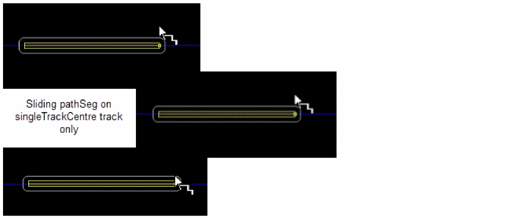
While sliding a pathSeg from a singleTrackCenter track to a non singleTrackCenter track, perform the following steps:
-
Change the width of the pathSeg to another value, which is not the same as the
minWidth. (The width is not adjusted to thesingleTrackCentertrack width when it is on thesingleTrackCentertrack) -
Press
Ctrl + Shiftto slide the pathSeg. The pathSeg can now move freely.
- (Optional) Change the width of the pathSeg, if required.
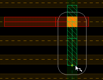
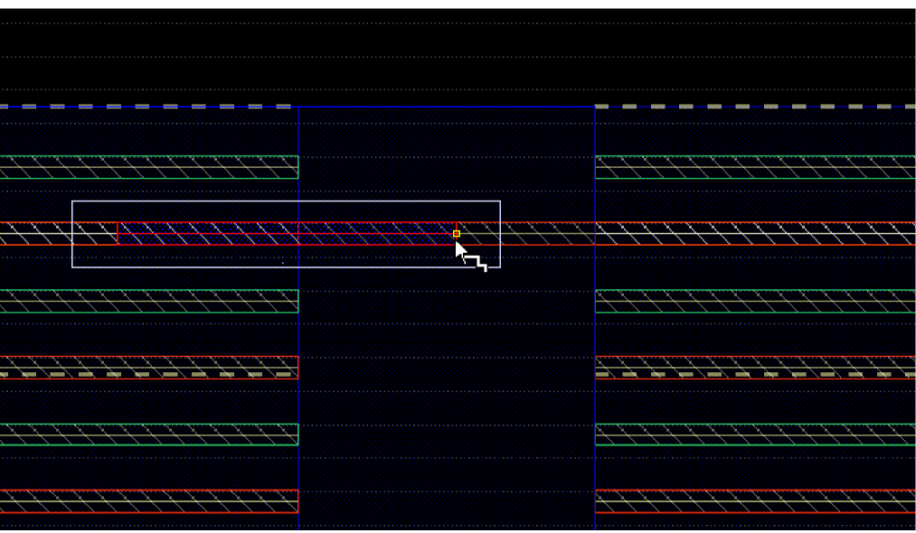
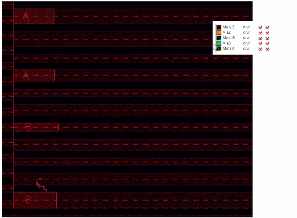
Automatic Via Insertion during Wire Snapping
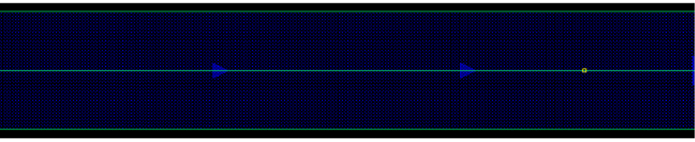
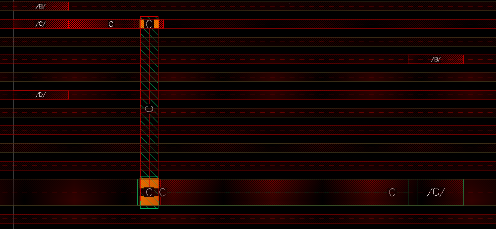
During wire creation, the track magnet snaps to the intersection of the upper or lower layer tracks. When you click on the track intersection, a via is automatically placed using the active width spacing pattern and the wire then changes direction and moves in the perpendicular direction, as shown in the following figure.
You can also place a via before clicking on a track intersection by using the Via up to <layer name> and Via Down to <layer name> options in the Create Single Wire context-sensitive menu. In this case, the wire always snaps at the track intersection, as shown in the following figure.
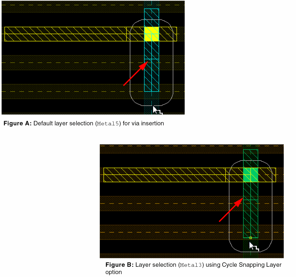
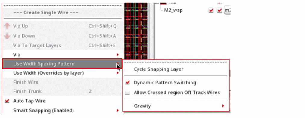
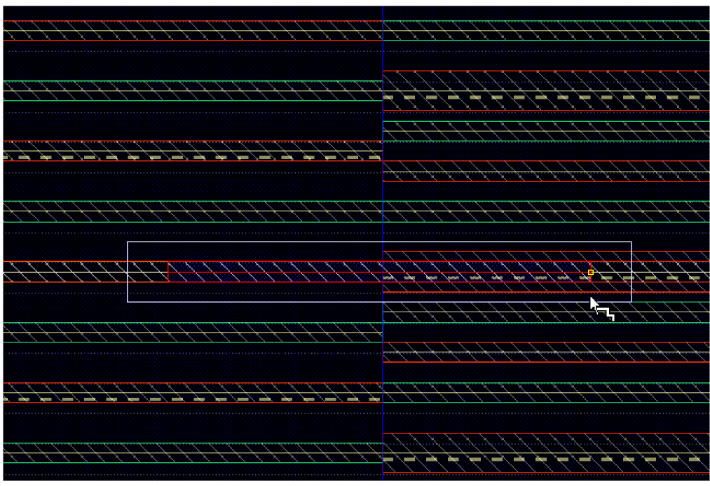
After the via is automatically placed, one of the metal layers is selected by default if the tracks of the lower and upper layers coincide. However, you can switch between the valid tracks of the upper and lower layers by selecting the Cycle Snapping Layer option in the Use Width Spacing Pattern submenu.
In the following set of figures, Figure A shows that the wire is created on Metal4, and when the via is placed on the track intersection, Metal5 is selected as the default layer.
Figure B displays the switch between the selected layers when the Cycle Snapping Layer option is clicked and Metal3 layer is now selected.
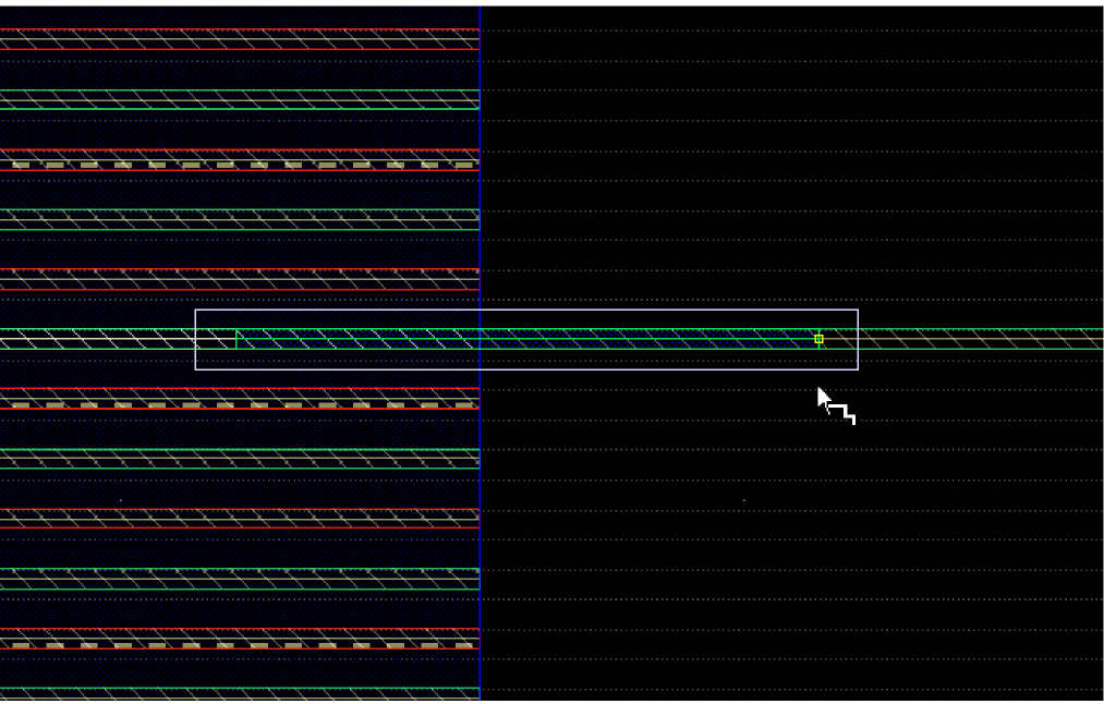
If the tracks of the lower and upper layers do not coincide, which means that the active pattern on the upper layer is different from that in the lower layer, then the layer at the track intersection is picked. However, you can slide the wire across the tracks to automatically change the layer and the corresponding via using the Ctrl+Shift bindkey. The following figure displays how the wire slides across the tracks and changes the layer and the corresponding via.
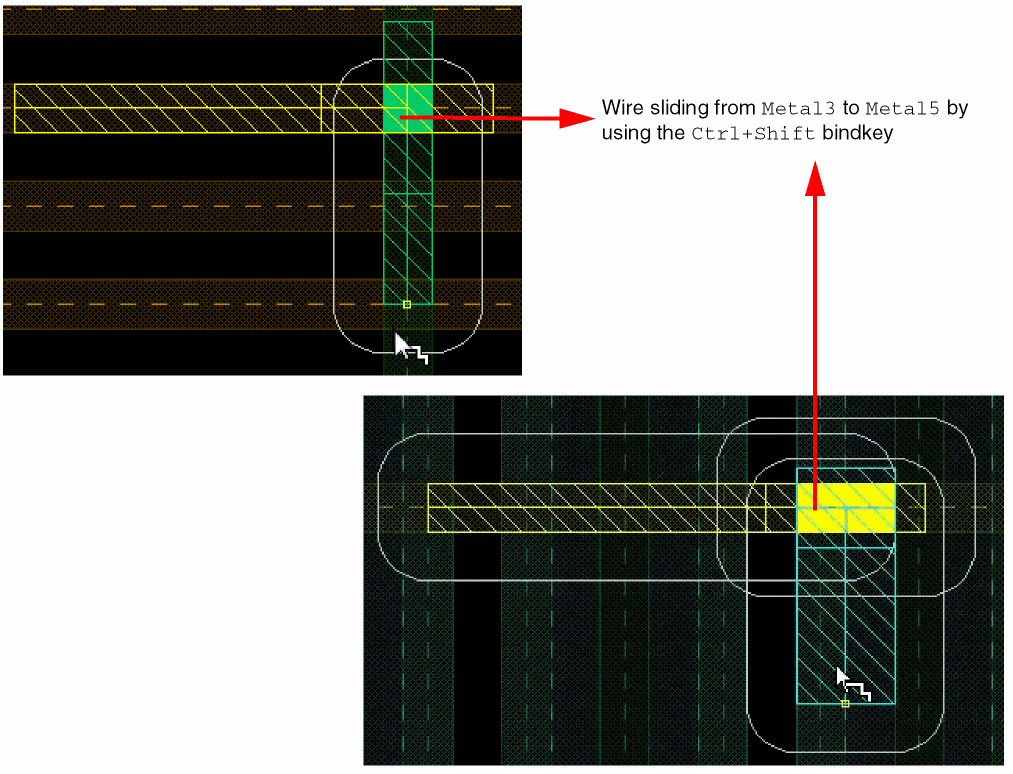
It also allows you to change the tracks on the same layer. The layer changes when the tracks are not aligned. If the tracks are aligned, the previous layer is preserved.
Snapping on WSP for Assisted Routing Commands
In the Layout Editor Options form, when you select the wire snapping option, Snap Pattern, the segments and vias are snapped to the active width spacing pattern track. The new segment inherits the width of the track it overlaps, as shown in the following figure.
In addition, when the MPT support is enabled in Palette, the wire segment also inherits the color and lock information of the active width spacing pattern track, as shown in the following figure.
Working with Width Spacing Patterns During Wire Editing
The Use Width Spacing Pattern option in the Create Single Wire context-sensitive menu lets you perform the following tasks.
The following figure shows the Use Width Spacing Pattern option in the Create Single Wire context-sensitive menu.
Switching Patterns Dynamically
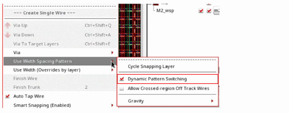
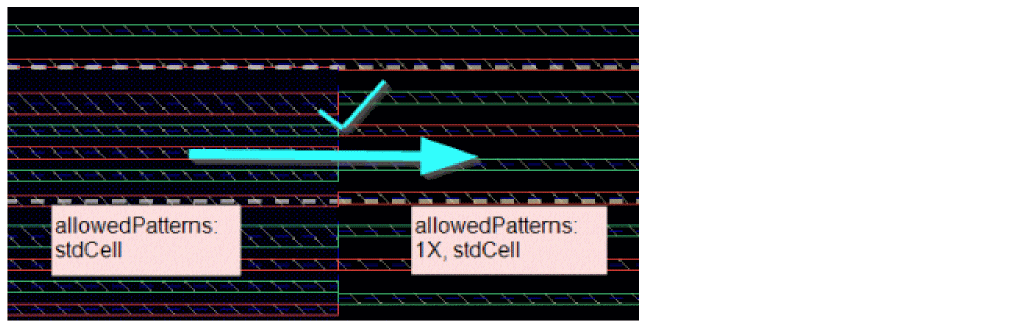
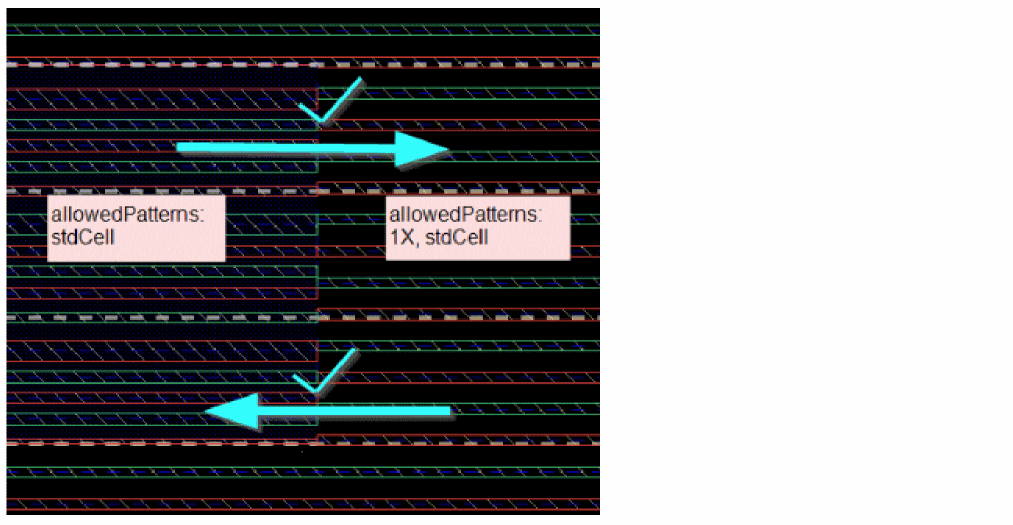
Pattern switiching happens dynamically letting you cross region boundaries only if the WSP track on which you started creating the wire has allowed WSP tracks.
When Dynamic Pattern Switching is enabled, it checks to ensure that the pathSeg you started on a track in one region can cross a region boundary. The target region should have a track that is a member of the allowed WSP patterns in the other regions.
-
consider that a region is defined with only a
stdCellpattern. ThestdCellpattern is the currently active pattern of the other region. -
consider that the global region has two patterns:
1XandstdCell. In this region,1Xis the currently active pattern.
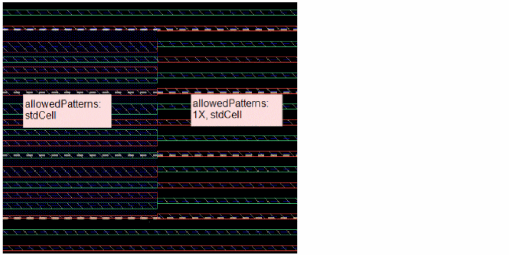
Now, start a wire on a wide track of the stdCell pattern in the region. Without dynamic pattern switching, 1X being the currently active pattern, the wire can be drawn only within the region. However, with dynamic pattern switching enabled, the wire can cross the region-to-global boundary. Even though 1X is the currently active pattern, the wide track with the stdCell pattern in the global region lets the wire cross the region. Hence, the pattern is dynamically switched from 1X to stdcell in the global region without changing its currently active pattern.
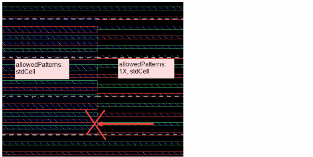
If you start a wire from a global region with 1x as the currently active pattern, then even with dynamic pattern switching enabled, the wire cannot cross the global-region boundary. This is because 1X is the currently active pattern in the global region, which is not the allowed WSP pattern in the other region. Therefore, the wire is unable to cross the global-region boundary.
Environment Variable: enableDynamicPatternSwitching
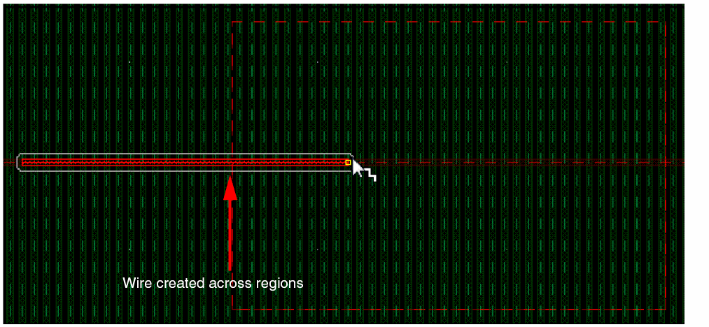
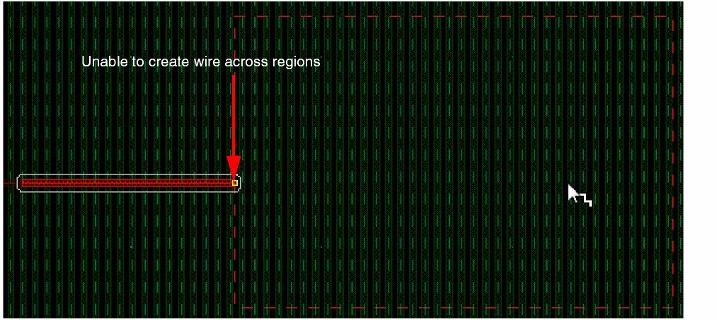
Crossing Region Boundaries
When a wire is created on global and local regions with non matching WSPs, the wire is not allowed to span the region and terminates at the region boundary.
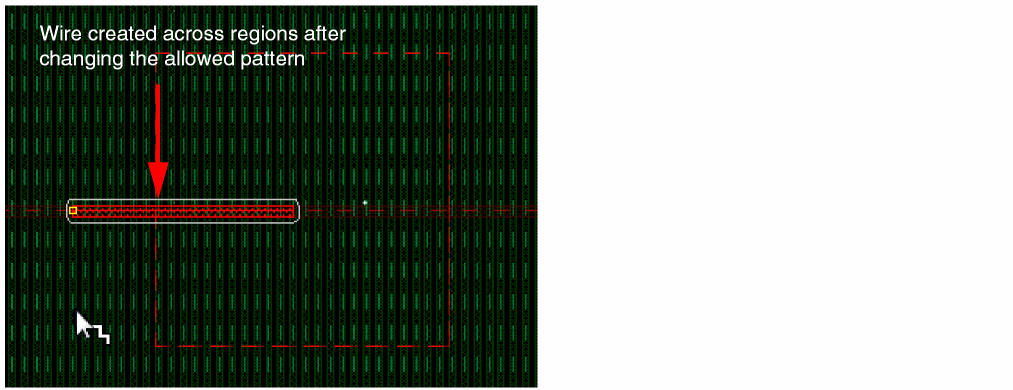
Using the Allow Crossed-region Off Track Wires option in the Use Width Spacing Pattern menu in the Create Single Wire context-sensitive menu, you can ignore the region boundary and continue routing across regions.
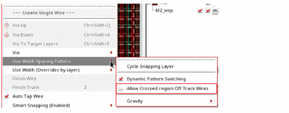
When the Allow Crossed-region Off Track Wires option is selected, it lets a wire cross regions, regardless of it being on track or off track and the patterns for secondary regions. The end point of the wire can be across a region boundary such that it is off track or on track with a different color and width. When the option is unselected and the WSP tracks are not identical, the pathSeg stops at local region boundaries.
Environment Variable: adjustEditedViasParams
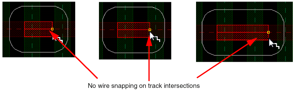
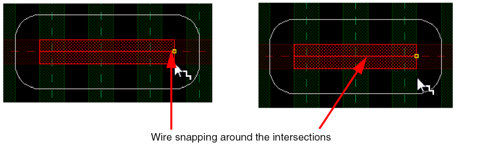
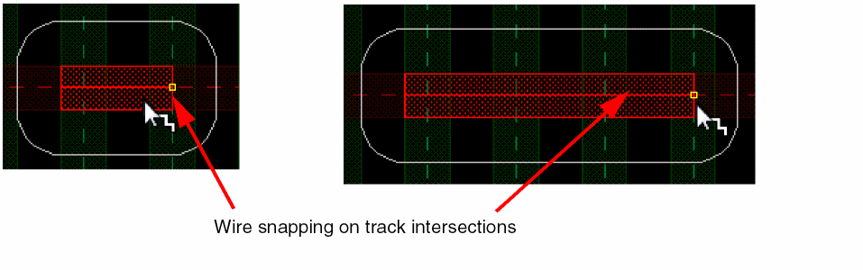
Wire Editor Gravity
In order to ease the creation of local interconnect wires and to control the magnetic force to track intersections, use the Gravity option in the Use Width Spacing Pattern menu of the Create Single Wire context-sensitive menu. Using the Gravity options, you can control how the cursor gravitates towards track and snap pattern intersections.
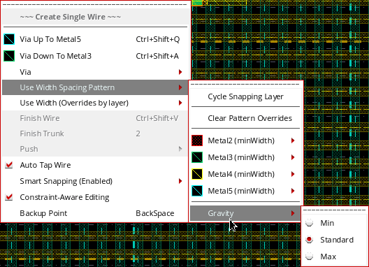
-
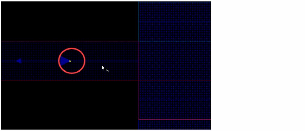
When set to Min, there is no snapping on track and snap pattern intersections and the mouse pointer gravitates pixel by pixel, as shown in the figure below.
-
When set to Standard, the wire snaps on the track and snap pattern intersections if the mouse pointer projection on the track axis is around the intersection.
-
When set to Max, the wire always snaps on the track and snap pattern intersections, as shown in the following figure.
Automatic Switching of the Active Pattern Across Regions
Wire editing provides you the flexibility of automatically switching patterns when crossing regions. You can switch an active pattern of a local region to the active pattern of the global region, even if the active pattern of the local region is not the default but is one of the allowed patterns.
The following figure shows that minWidth is the active pattern on Metal2 layer for the global region and 2XWidth is the active pattern of the local region. However, because 2XWidth is an allowed pattern in the local region, you are able to create a wire starting from the global region and continuing to extend it in the local region.
However, if an active pattern of a local region is not an allowed pattern in the global region, then you cannot create a wire across the two regions. The wire is snapped at the boundary of the region. The following figure shows that a wire is created on Metal2 layer in the global region for which the default active pattern is 2XWidth. The 2XWidth is not an allowed pattern in the local region. Therefore, the wire is not able to cross across regions and is snapped at the boundary of the local region.
If the local and global regions have different active and allowed patterns on a metal layer, you can change the active and allowed patterns of a region while creating a wire. For example, a local region has 2XWidth as the active pattern and the global region has minWidth as the only allowed pattern on Metal2 layer. Once you start creating a wire, you can change the active and allowed patterns of a region using the Width Spacing Pattern assistant. When you change the allowed patterns of a region and make the patterns available for the other region, you can traverse through and continue to create a wire in the other region as well.
The following figure shows that you can create a wire starting from a local region, which has a 2xWidth pattern, and continue to create the wire in the global region for which you have changed the allowed patterns.
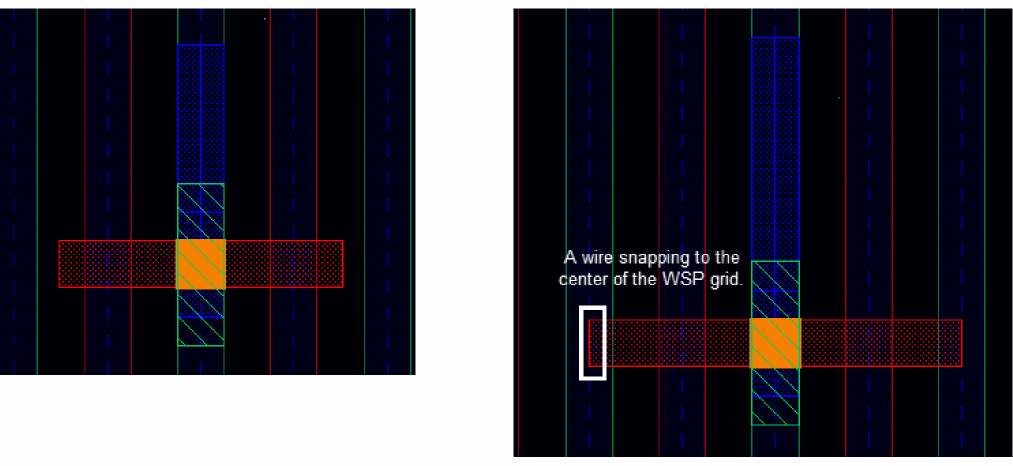
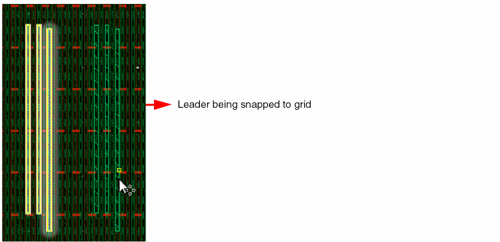
Working with Selected Sets of Wires
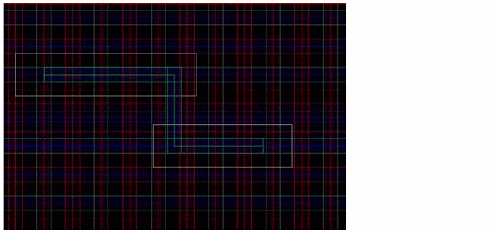
In wire editing, when multiple wires are selected and are moved, copied, or stretched, all the selected wires move together as a group. The wire that is closest to the point clicked on the layout canvas is highlighted and becomes the leader as shown in the following figure. From the selected set, only the leader is snapped to its corresponding grid. The remaining wires in the selected set move by the same distance but are not snapped to their corresponding grid.
Nested WSP Regions
A WSP region can have a local widthSpacingSnapPatternDef and not just the global widthSpacingSnapPatternDef. The Wire Editor can display and use the patterns of WSP regions embedded inside other WSP regions. Several regions can be nested in one and within one another.
The following are special cases of partially and fully overlapping regions that you can come across while creating wires.
- Region R1 Partially Overlaps Another Region R2
- Two Regions Overlap With the Exact Same Boundary
- Region R1 Partially Overlaps Another Region R2 With the Same Width Spacing Pattern
- Region R1 is Fully Enclosed in Another Region R2
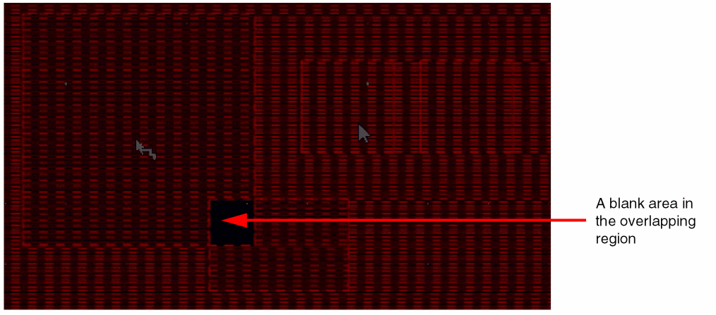
Region R1 Partially Overlaps Another Region R2
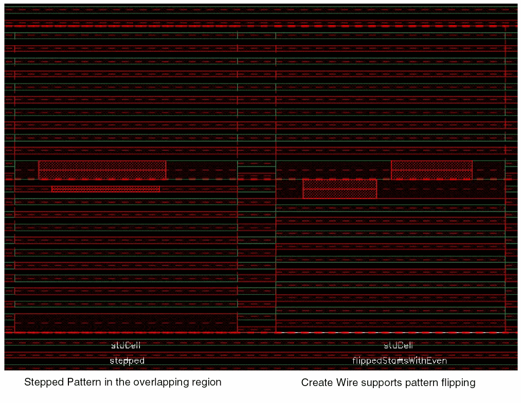
The region R1 has WSP1 as the active pattern and the region R2 has WSP2 as the active pattern. When the Create Wire command is invoked, the region R1 will have WSP1 pattern and region R2 will have WSP2 pattern. However, the overlap area of the two regions does not have any pattern available and displays a blank area. Also, a wire cannot be created and snapped inside the overlapping region.
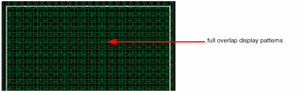
Two Regions Overlap With the Exact Same Boundary
The two regions R1 and R2 have the exact same boundary and completely overlap each other. When the Create Wire command is invoked, the pattern of each region is displayed in the overlapped region. You can now create a wire on any of the WSP pattern displayed in the two exactly coincident regions on the same layer. Therefore, snapping is possible to either region’s WSP active pattern.
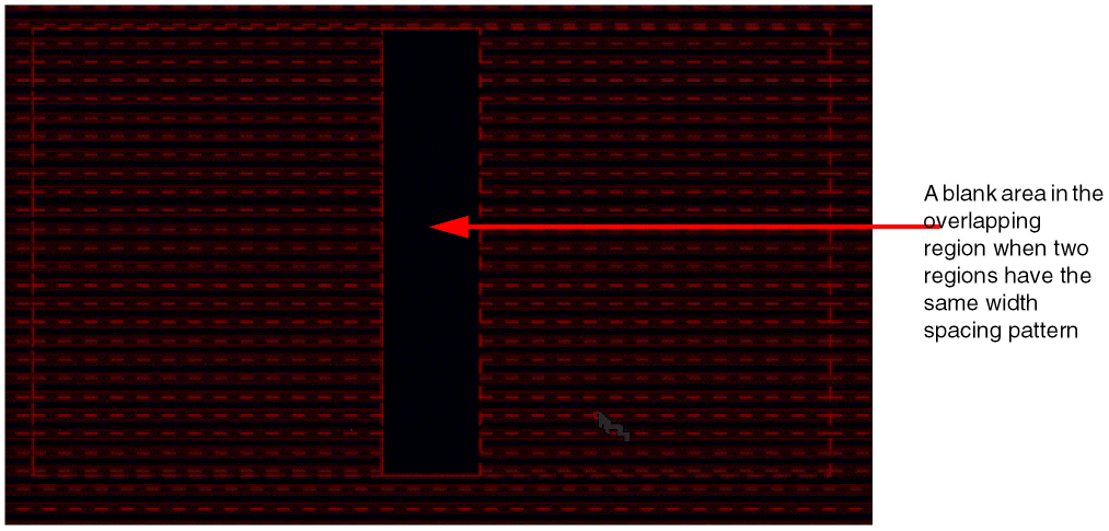
Region R1 Partially Overlaps Another Region R2 With the Same Width Spacing Pattern
When two regions R1 and R2 partially overlap and use the same active pattern, there is no pattern in the overlapping region. The active pattern is valid only where the two regions, R1 and R2, do not overlap each other.
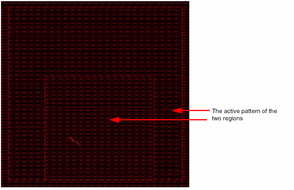
Region R1 is Fully Enclosed in Another Region R2
Region R1 has 2xWidth as the active pattern and region R2 has WSP1 as the active pattern. When region R2 is fully enclosed within region R1, on invoking the Create Wire command, the dynamic display shows the active pattern of each region as shown in the following figure. In other words, WSP1 is available inside region R2 and 2Xwidth is available in region R1 where R2 is not overlapping (R1-R2).
When a wire is created inside the enclosed region (R2), snapping and wire creation is possible only inside the enclosed region. However, if a similar pattern is available in the enclosing region (R1), the wire can cross the region boundary and continue snapping in region R1.
Similarly, if a wire starts from the enclosing region (R1), it stops at the enclosed region (R2) boundary. If a similar pattern is available in the enclosed region (R2), the wire can cross the boundary and continue snapping in the enclosed region (R2).
Supporting pathSegs with Different WSPs across Regions
Wire editing provides an environment variable, adjustEditedViasParams, which when set to t provides the flexibility to cross the region boundaries even when the WSPs (and allowed WSPs) do not match. This means that the two regions have different WSPs, which is not supported when the switching of active patterns across regions is automatic.
In such cases, the pathSeg acquires all properties from the start point and allows the end point to cross region boundaries. The following figure shows that the pathSeg crosses the region when the two regions having the same WSP pattern are overlapped and there is an empty track space in between.
Crossing the boundary region is also possible when there are two abutted regions with different WSPs. The following figure shows that the pathSeg crosses the regions for which the tracks do not match.
Another case in which wire editing lets the pathSeg cross the region boundaries is when one of the two regions is a global region, which implies that there is only one local region. The following figure shows that the pathSeg crosses from a local region to a global region that does not have any defined WSP.
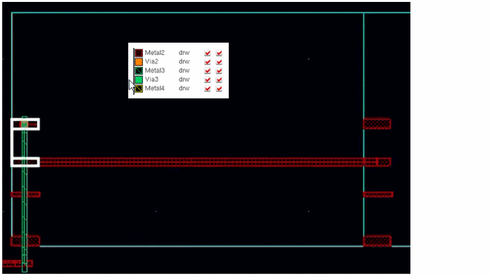
Wire Editor Hierarchy Support
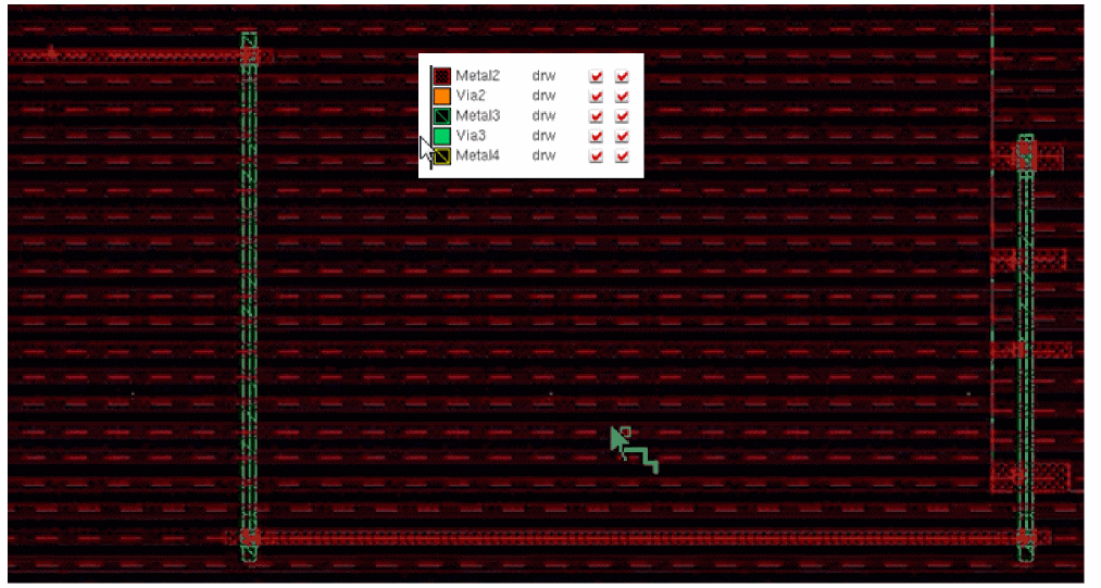
By default, the width spacing patterns of pins are not available as instance pin patterns. Consequently, the global width spacing pattern is available in the instance on a metal layer. For example, the following figure shows that the global width spacing pattern on Metal2 is being considered even though the instance pins have been created using different patterns.
To identify the pattern of the instance pins, select the Instance Pins Patterns check box in the Wire Snapping section of the Layout Editor Options form and then run the Create Wire command.
When enabled, the width spacing patterns of an instance are considered instead of the width spacing patterns of the enclosing region.
- The width spacing patterns on the layers below the lowest instance pins layer are not accessible.
- On instance pins layers, only the patterns of the instance whose tracks match the instance pins are available within the instance bounding box.
- The width spacing patterns of the enclosing region are only available above the highest instance pins layer.
When the Instance Pins Patterns check box is selected, the global width spacing pattern on Metal2 stops at the instance boundary and the pin width spacing patterns are used to make connections inside the instance. However, in Metal3, the global width spacing pattern is still available in the instance. The pin pattern is available only inside the instance boundary and is not exposed outside the instance boundary, as shown in the following figure. Also, the instance pin pattern allows to connect to the pattern of the upper layer, which is coming from the global region.
The following are some examples of connections from pins using their own patterns.
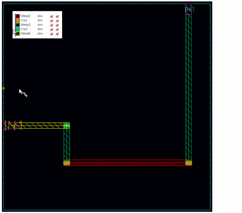
In this example, you have a Metal2 top-level pin and two instances of the same master side by side. The following figure displays the connection that exists between the instance pin and the top-level pin.
If the top-level pin has the same width spacing pattern as that of the instance pin, you can make a direct connection between the instance pin and the top-level pin without changing the metal layer, as shown in the following figure.
You can also make a pin-to-pin connection between the pin on one instance to the pin on the other instance using the pin pattern.
The following are some examples of an instance with pins on several layers.
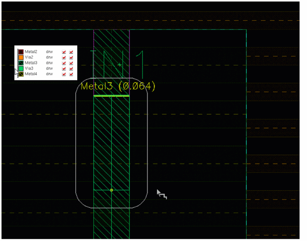
In this example, there is a pin on Metal3 and Metal4 layer. Therefore, for Metal3 and Metal4, the pin instance width spacing pattern can be used. The following figure shows the width spacing pattern of the instance pin on Metal3 layer.
Because there is no pin available on Metal2 layer and Metal2 is lower than the highest, or below the highest metal layer of the instance for which width spacing patterns are available, no width spacing pattern is available inside the instance.
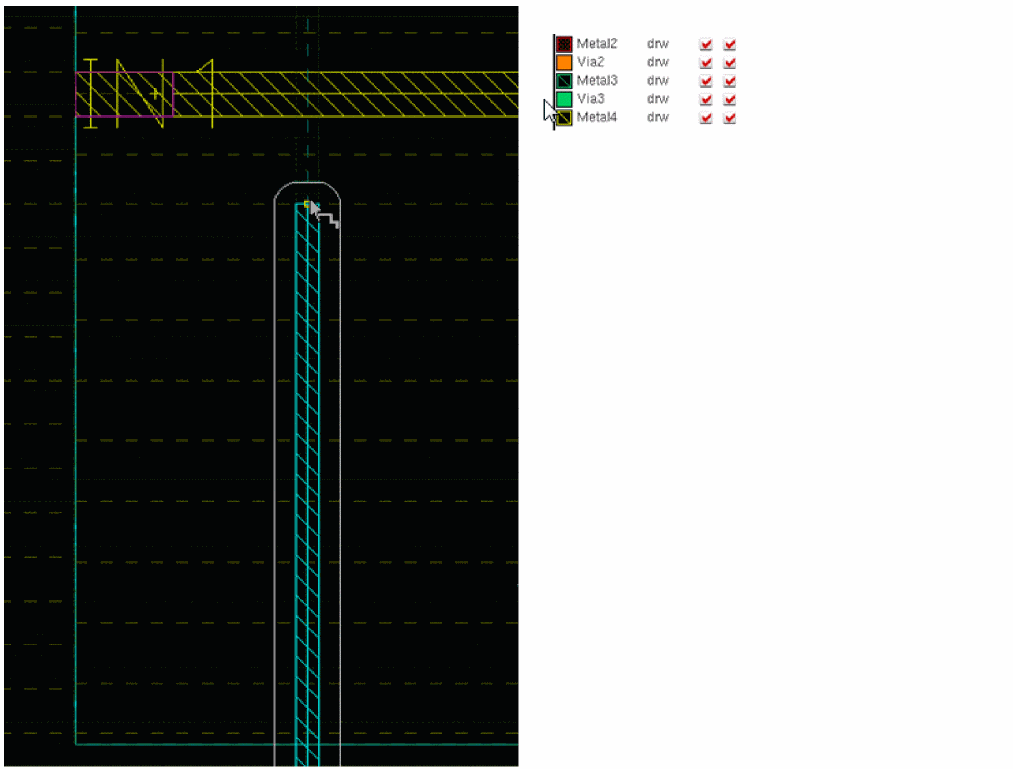
Again, there is no pin available on the Metal5 layer and Metal5 is higher than the highest, or above the highest metal layer above the instance. Therefore, the global pattern is available inside the instance on Metal5, as shown in the following figure.
Pattern Flipping Support
Pattern flipping enables you to flip an existing WSP pattern in alternate periods in a region. WSP pattern flipping can be specified at two levels:
For more information, see
When a pattern in a region is flipped, a wire created on a track in that region automatically adjusts to the flipped pattern, as shown in the following figure.
If a WSP pattern has a track with offset zero but no track at the top period line, then the track is generated on every period line. In addition, if a WSP pattern has a track with offset zero as well as a track at the top period line, then the pattern should only be used with a flipped repeat mode. In this way only compatible tracks will overlap.
If a WSP with offset zero has tracks with different widths at the top and bottom of the period, the pattern can only be flipped. This ensures that the overlapping tracks are compatible and can be merged.
Return to top