From a high-level point of view, a mixed-signal flow including real-number modeling could look as follows.
Concept Engineering is developing the system-level view of the chip. Architectural trade-offs are made based on the system-level simulation. This is also the starting point for the baseline specification for the building blocks. For the system-level simulation, top-down models are used (See the Concept Engineering View figure). Using the real number models is an attractive possibility because it enables the connect engineer to use the same simulation environment as the detailed block implementation. Thus, the real number models are used as initial specifications for the block-level implementation and are exchanged seamlessly between the concept and block-level flows.
Besides the specification and interface definitions, a high-level verification plan is developed based on the implemented features and blocks.
Figure 1.1: Concept Engineering View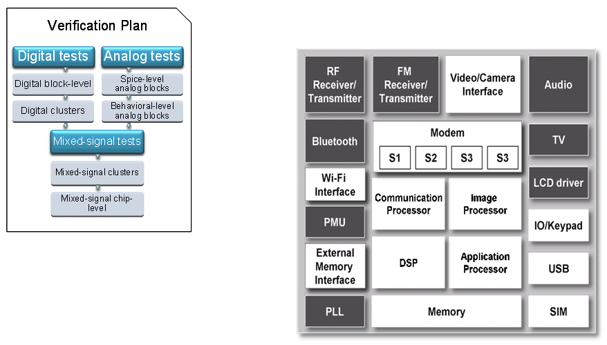
The digital block-level implementation and verification flows are mainly based on languages, such as VHDL and Verilog. Tests are created in the design language or special verification languages, such as e or SystemVerilog as shown in the following figure.
The verification plan is updated, if needed, based on the implementation details and features of each digital block.
Figure 1.2: Pure Digital Testbench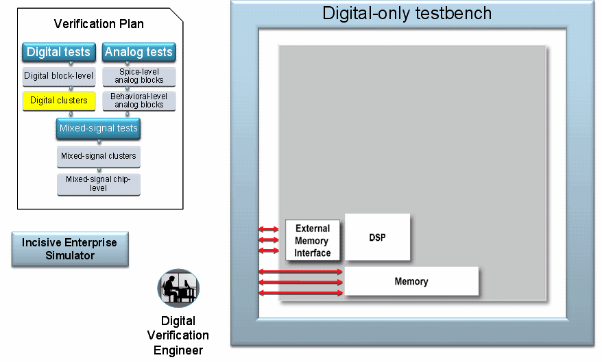
Over time, the number of blocks and the number of tests grow as shown in the following figure. Due to the high simulation performance, a large set of digital blocks in a complex testbench is mostly uncritical from the simulation point of view.
The pure digital verification results are captured in the Verification metric (coverage).
Figure 1.3: Top-level Digital Testbench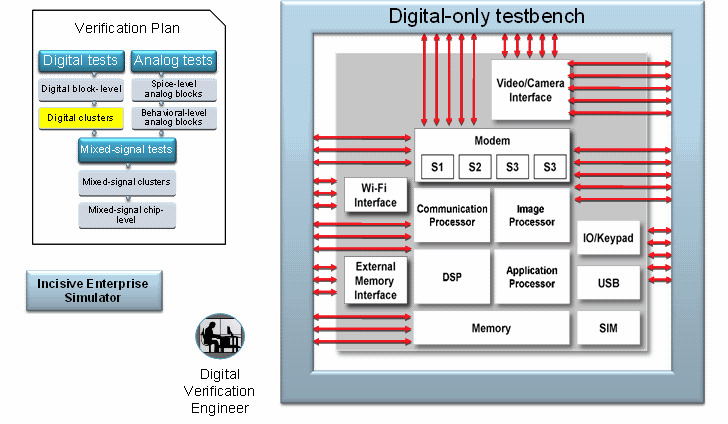
A similar process is followed on the pure analog implementation side as shown in the following figure. However, the implementation and simulation environment are different. Analog users mostly use the Virtuoso Analog Design Environment (ADE) as their working environment. The testbench is a schematic. There are often different test benches and ADE states for a single analog block. For example, for an AC configuration and a transient simulation.
Verification is often based on visual waveform inspection. Given the level of detail and size of the blocks, this is not a limiting factor for the analog designer.
To improve simulation performance for top-level verification, a real value model needs to be created. This model is validated with the same analog testbench used for the transistor model to ensure whether the functionality matches the transistor-level reference or not as shown in the following figure.
The model validation process is scheduled as a regression run to ensure that the model stays in sync with potential design changes later in the flow.
Figure 1.4: Verifying the wreal Model in the Analog Environment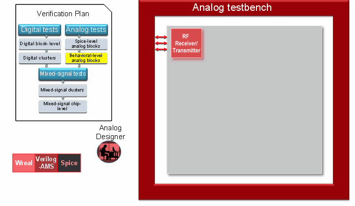
Both the analog and digital implementation flows are often mixed-signal where the analog part is represented as the transistor-level model or behavioral real model for functional verification as shown in the following figure. The detailed analog/digital performance verification, such as impedance matching, noise/gain levels needs to be verified as completely as possible at this block-level since the simulation performance does allow a very accurate transistor-level simulation.
This is a critical verification step in the overall chip verification task. The top-level verification based on real values is complementary to these low-level verification tasks. They are not replacing them by any means.
Figure 1.5: Mixed-Signal Block-Level Test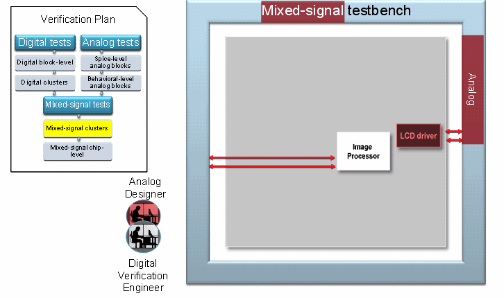
As shown in the following figure, for the top-level verification, all analog content is replaced by the real value models. This ensures a high simulation performance that is required for the top-level verification tasks.
Figure 1.6: Top-level wreal Testbench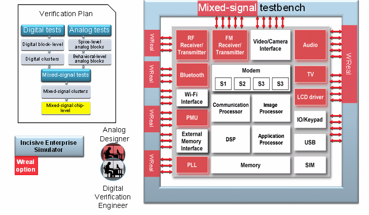
Once the main functional verification is done at a high level of abstraction, it might be necessary to replace some critical blocks with the transistor-level representation again to ensure that all analog effects are correctly verified.