


|
|
|||||||||
|
|
|
|
|
|
|
|
|
|
|
This chapter describes the Virtuoso® UltraSim™ simulator post-layout simulation options.
The Virtuoso UltraSim simulator is designed to handle the demands of most of the post-layout simulation flows (refer to Figure 4-1 for more information) and supports the backannotation of parasitic resistors and capacitors (RCs) from a detailed standard parasitic format (DSPF) file, a standard parasitic exchange format (SPEF) file, parasitic capacitance from a node capacitance file, and extracted device layout parameters from a DPF file.
|
|
Flat RC netlist file is a simple approach, allowing you to use a large number of elements and devices in the netlist, but it tends to be more memory and time consuming. An example of a flat RC netlist is a flat DSPF file. |
|
|
Hierarchical RC netlist file is an approach in which the Virtuoso UltraSim simulator preserves the hierarchical structure of the netlist file to reduce run time and memory requirements. This simulation method is generally faster than the flat RC netlist file approach. The main drawback is that the parasitic information is embedded inside the netlist file, making it more difficult to extract the information. |
|
|
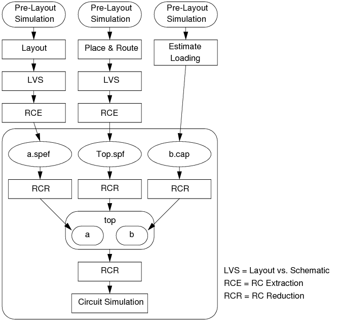
Backannotation and stitching of parasitic files is an approach that has the simulator preserve the design hierarchy to reduce run time and memory requirements, and accepts mixed post-layout netlist file formats to support simulation of circuit designs. For example, designs in which some blocks have successfully passed layout versus schematic (LVS) verification and have post-layout netlist files, whereas other blocks remain at an early stage of development and only have estimated capacitive loading. See Figure 4-2 to view this full-chip simulation flow example graphically. |
Figure 4-1 Post-Layout Simulation Flow
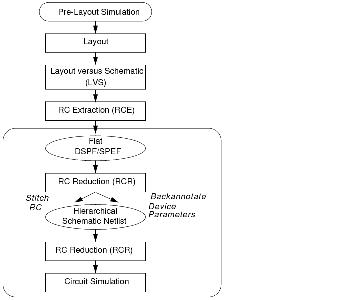
Figure 4-2 Full-Chip Simulation Flow
The simulator also provides the high-level postl option which you can use to control the trade-off between simulation accuracy and performance. Cadence recommends that you read more about "postl" before starting a post-layout simulation.
The Virtuoso UltraSim simulator supports the following RC reduction options:
Note: A period (.) is required when using SPICE language syntax (for example, .usim_opt ccut).
This option allows you to cut capacitors, depending on the value of the capacitors. Capacitors less than ccut are cut (that is, open circuited) during parsing. The ccut option is helpful with large post-layout netlist files containing small capacitors. To reduce memory consumption, ccut needs to be defined at the beginning of the netlist file, so cutting is performed during parsing. The default is 0.
tells the Virtuoso Ultrasim simulator to cut all capacitors with a value < 0.1 ff during parsing.
This cgnd option defines the absolute threshold value for grounding coupling capacitors. A capacitor is considered a coupling capacitor if neither of its terminals are connected to a ground voltage source. A ground voltage source is one that has a path to ground directly or through other voltage sources. Coupling capacitors can lead to significantly longer run times and may not contribute appreciably to simulation accuracy. A coupling capacitor can be split into two grounded capacitors with the same capacitance value: One at each terminal of the original capacitor.
With this option, a coupling capacitor is grounded if its value is less than cgnd. The grounding of coupling capacitors is automatically enabled by setting the high-level post-layout control parameter postl. The default value depends on the setting for postl. See Table 4-1 for more details.
tells the Virtuoso UltraSim simulator to ground all coupling capacitors with a value < 1 pf.
The cgndr option defines the relative threshold value for grounding coupling capacitors. A coupling capacitor is grounded if the ratio of its value to the total node capacitance on both sides is less than cgndr. The range of cgndr is between 0 and 1. The default value depends on the setting for postl. See Table 4-1 for more details.
The rcr_fmax option defines the maximum frequency of interest for RC reduction (default is 1.0 GHz.). If the chosen value for rcr_fmax is less than the maximum operating frequency of interest, you may experience accuracy loss for frequencies higher than the specified rcr_fmax value.
This option can be used to cut resistors with values larger than the specified rcut value (that is, open-circuit resistors). The default is 1e12 ohm.
tells the Virtuoso UltraSim simulator to cut all resistors with a value > 1e14 ohm.
Signal net resistors with an absolute value less than rshort are short-circuited. The default value depends on the setting for postl. See Table 4-1 for more details.
For any resistor connected to an independent voltage source, if its absolute value is less than rvshort, the resistor is short-circuited. The default value depends on the setting for postl. See Table 4-1 for more details.
usim_opt rvshort=1 subckt=SUPPLY
.usim_opt rvshort=1 subckt=SUPPLY
postl=0 is designated for simulation of a pre-layout netlist file containing a few resistors and capacitors. The Virtuoso UltraSim simulator does not perform RC filtering or reduction, except shorting extremely small resistors, and grounding extremely small capacitors to allow stable simulation.
postl=1, postl=2, and postl=3 are intended for post-layout simulation. As the postl level is raised, the Virtuoso UltraSim simulator applies more aggressive RC reduction. As a result, run time and memory usage are reduced at the cost of slightly degraded simulation accuracy.
For postl=4, most of the resistors in signal nets are eliminated and most coupling capacitors are grounded. This produces a post-layout simulation where only grounded parasitic capacitance is taken into account.
Note: For EMIR analysis, when postl is set to 0, the default value for rshort and rvshort is 1e-6.
usim_opt postl=1 rshort=1 subckt=VCO
.usim_opt postl=1 rshort=1 subckt=VCO
The Virtuoso UltraSim simulator applies postl=1 to all instances of subcircuit VCO. Any resistors connected to signal nets in all instances, if the values of the resistors are less than 1 ohm, are short-circuited. Default values are used for all other options associated with postl, such as rcr_fmax, rvshort, cgnd, and cgndr.
The preserve=1 command is used to exclude resistors and capacitors from RC reduction.
Note: The default value of the preserve option is 0.
If all of the options are used in the statement, the Virtuoso UltraSim simulator only uses the resistors and capacitors shared between the specified options (that is, RC reduction options, such as postl, rshort, and rvshort are applied only to the resistors and capacitors not specified in this option).
usim_opt preserve=1 inst=x1.x3.r1 preserve_file=["inst.txt"]
.usim_opt preserve=1 inst=x1.x3.r1 preserve_file=["inst.txt"]
The inst.txt file contains the following resistors:
tells the Virtuoso UltraSim simulator to exclude the x1.x3.r1, X3.x2.res1, X2.res3, and R1 resistors from RC reduction.
The capfile option specifies how to load a cap file into the Virtuoso UltraSim simulator.
|
The full hierarchical path of the instance for which the cap file is prepared. Wildcards are supported (for more information about wildcards, see "Wildcard Rules" ). You can also specify the subcircuit name as the path. All instances of the specified subcircuit are stitched. If the path is not specified, and the cap file contains a .subckt statement, all instances with the same subcircuit name are stitched (or the simulator assumes that the cap file is prepared for the entire design, and the quotation marks can be omitted). |
|
|
The name of the parasitic file. The Virtuoso UltraSim simulator can read compressed parasitic files in gz format (files need to have the .gz extension). |
For more information about parsing options for cap files, refer to "Parsing Options for Parasitic Files".
For the design shown in Figure 4-2 , the parasitic files need to be specified as follows (Spectre syntax example):
usim_opt spef="a a.spef" spf="Top.spf.gz" capfile="b b.cap"
Note: You need to make sure the parasitic elements specified in the parasitic files do not overlap and that Top.spf is extracted until the level for the a and b instances is reached (that is, the file contains all elements inside top, excluding the elements in a and b).
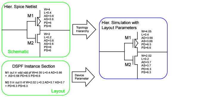
The dpf option specifies how a parasitic DPF file is loaded into the Virtuoso UltraSim simulator. You can also use dpf to stitch the instance section of a DSPF file, causing the parasitic resistors and capacitors to be ignored. The simulator supports backannotation of DPF files. Figure 4-3 shows the process of DPF file stitching using the simulator.
Figure 4-3 Stitching a DPF Parasitic File
|
The full hierarchical path of the instance for which the parasitic file is prepared. Wildcards are supported (for more information about wildcards, see "Wildcard Rules" ). You can also specify the subcircuit name as the path. All instances of the specified subcircuit are stitched. If the path is not specified, and the parasitic file contains a .subckt statement, all instances with the same subcircuit name are stitched (or the simulator assumes that the parasitic file is prepared for the entire design, and the quotation marks can be omitted). |
|
|
The name of the parasitic file. The Virtuoso UltraSim simulator can read compressed parasitic files in gz format (files need to have the .gz extension). |
For more information about parsing options for DPF files, refer to "Parsing Options for Parasitic Files".
tells the Virtuoso UItraSim simulator to only stitch the instance section of the parasitic file top.spf.
|
The full hierarchical path of the instance for which the parasitic file is prepared. Wildcards are supported (for more information about wildcards, see "Wildcard Rules" ). You can also specify the subcircuit name as the path. All instances of the specified subcircuit are stitched. If the path is not specified, and the parasitic file contains a .subckt statement, all instances with the same subcircuit name are stitched (or the simulator assumes that the parasitic file is prepared for the entire design, and the quotation marks can be omitted). |
|
|
The name of the parasitic file. The Virtuoso UltraSim simulator can read compressed parasitic files in gz format (files need to have the .gz extension). |
.subckt sub1 n1 n2
...
.ends sub1
.subckt sub2 m1 m2
...
.ends sub1
X1 node1 node2 sub1
X2 node3 node4 sub2
X3 node5 node6 sub2
If .usim_opt spf="X2 parasitic.dspf" is used, the stitching is limited to instance X2. If .usim_opt spf="sub2 parasitic.dspf" is used, the simulator applies the stitching to all sub2 instances, which include X2 and X3.
This option is used to specify how a parasitic SPEF is loaded into the Virtuoso UltraSim simulator.
For more information about parsing options for DSPF and SPEF files, refer to "Parsing Options for Parasitic Files".
The Virtuoso UltraSim simulator also supports stitching of hierarchical SPEF files produced by the Cadence Assura™ physical verification tool. If you specify the SPEF file that corresponds to the highest level of hierarchy of interest, the corresponding SPEF file for the sub-levels is automatically loaded into the simulator via the *define statement (per the convention adopted by Virtuoso UltraSim and Assura in which the first string of the *define statement indicates the instance name of the sub-block and the second string indicates the name of the SPEF file for the instance).
In general, the Assura RCX tool names the SPEF file and corresponding DPF file as follows: blockname.spef and blockname.dpf (for example, vco.spef and vco.dpf). By default, the Virtuoso UltraSim simulator automatically stitches the corresponding DPF file for each stitched SPEF file, provided the DPF files exists in the path. The usim_opt spfinstancesection=off option can be used to turn off stitching of the DPF file, useful when you do not want to stitch the corresponding DPF file.
The top level of the SPEF file is named top.spef and contains
To invoke stitching, use the following statement (Spectre syntax example):
The simulator searches for a file named INV.spef for the X1 and X2 instances. If INV.spef is not found, the simulator issues a warning.
Note: You can specify the path in the *define statement and the .spef suffix can be omitted.
The simulator supports the following parsing options:
A parasitic capacitor less than cmin is discarded (open circuited) during RC stitching. The default is 0.
Note: Capacitors in the pre-layout are not affected because they are not stitched.
tells the Virtuoso UltraSim simulator to discard any parasitic capacitors < 1 ff during stitching.
A parasitic coupling capacitor less than cmingnd is grounded during RC stitching (default is 0).
A parasitic coupling capacitor is grounded during RC stitching if the ratio of its value to the total node capacitance on both sides is less than cmingndratio (default is 0).
Note: The pre-layout capacitors are not affected.
This option controls the behavior of the dpfscale option. When dpfautoscale is set to on, dpfscale is set to the same value as the parameter scale. When dpfautoscale is set to off, dpfscale is independent of the parameter scale. The dpfautoscale option is on by default.
Note: When the model libraries contain options, such as scale, scalefactor, or geoshrink, it is recommended that you use the dpfautoscale=on setting instead of dpfscale.
tells the Virtuoso UltraSim simulator to use the value of the parameter scale for dpfscale.
This option specifies the scale factor for device geometry parameters (default is 1.0).
Note: The pre-layout device parameters are not affected by dpfscale.
This option skips the stitching of device parameters of the specified instances in the DPF file or in the instance section of a DSPF file. All parasitic RCs connected to the skipped instances are stitched. Complete hierarchical names for instances are required. Wildcards are supported. For more information on wildcards, see Wildcard Rules.
Skipped instances by dpfskipinst 8
Note: dpfskipinstfile, dpfskipsubckt and dpfskipsubcktfile are other related options that allow you to enable or disable device parameter stitching for specified instances or subcircuits.
tells the Virtuoso UltraSim simulator to skip the stitching of device parameters for the instance x1.x2.
This option skips the stitching of device parameters of instances that are listed in the specified file_name.
Note: dpfskipinst, dpfskipsubckt and dpfskipsubcktfile are other related options that allow you to enable or disable device parameter stitching for specified instances or subcircuits.
usim_opt dpfskipinstfile="file1"
.usim_opt dpfskipinstfile="file1"
And, the content of file1 is as follows:
tells the Virtuoso UltraSim simulator to skip the stitching of the device parameters of instances x1.xr2 and x1.xr.xd5 that are listed in file file1.
This option skips stitching the device parameters of all instances of specified subcircuits. All parasitic RCs connected to the skipped instances are stitched. Wildcards are supported (for more information about wildcards, see Wildcard Rules ).
Skipped subckts by dpfskipsubckt 80
usim_opt dpfskipsubcktfile="file1"
.usim_opt dpfskipsubcktfile="file1"
And, file1 contains the following information:
tells the Virtuoso UltraSim simulator to skip stitching of the device parameters of all instances of subcircuits mux4 and nand2.
This option is usually used when the resistance values appear suspicious, that is, non-physical. In general, this indicates that the extraction is questionable. Large resistors, such as 1.0e+9, may cause simulation problems. The option rmax helps bypass any extraction problem and continue with simulation.
This option applies the rmax value on the parasitic resistors of the specified layer. Multiple statements can be specified. The option is used when the extracted resistance values are unreasonably large on certain layers.
usim_opt rmaxlayer=1000000&ptab
usim_opt rmaxlayer=1000000&ptab0
usim_opt rmaxlayer=1000000&ntap
.usim_opt rmaxlayer=1000000&ptab
.usim_opt rmaxlayer=1000000&ptab0
.usim_opt rmaxlayer=1000000&ntap
tells the Virtuoso UltraSim simulator to treat any parasitic resistors on layers ptab, ptab0, and ntap with value greater than 1000000 Ohm as open circuit for layers.
If rmin is specified, a parasitic resistor less than rmin is shorted during RC stitching (default is 0).
Note: The pre-layout resistors are not affected by rmin.
This option applies the rmin value on parasitic resistors of the specified layer. Multiple statements can be specified. The option is used when the extracted resistance values are unreasonably small on certain layers.
usim_opt rminlayer=0.1001&nwell
usim_opt rminlayer=0.1001&dnwell
.usim_opt rminlayer=0.1001&nwell
.usim_opt rminlayer=0.1001&dnwell
.usim_opt rminlayer=0.1001&sub
tells the Virtuoso UltraSim simulator to short any parasitic resistors on layers nwell, dnwell and sub with value less than 0.1001 Ohm.
If rvmin is specified, a power net parasitic resistor less than rvmin is short circuited during RC stitching (default is 0).
Note: The pre-layout rail resistors are not affected by rvmin.
This option allows you to specify an alias for terminal names of a device or instance during stitching. In some cases, the terminal names used in the pre-layout netlist are not consistent with the terminal names in the DSPF/SPEF file, which causes mismatches during stitching. The spfaliasterm option helps resolve this inconsistency.
usim_opt spfaliasterm="dgnfet 1=D 2=G 3=S 4=B"
.usim_opt spfaliasterm="dgnfet 1=D 2=G 3=S 4=B"
inline subckt dgnfet (1 2 3 4 )
dgnfet (1 2 3 4) dgnfet l=l w=w …
However, on the extraction side, the inline subckt is treated as a regular MOSFET, and the terminal names in DSPE/SPEF file are (D G S B). By default, UltraSim cannot find the terminal name (D G S B) in the pre-layout netlist. As a result, you might see warning messages as below in the spfrpt file:
WARNING(:478) : Instance I1.m0 has no terminal named "B". Element ignored
WARNING(:493) : Instance I2.m2 has no terminal named "B". Element ignored
After the spfaliasterm option is used as specified in the example, the inconsistency is corrected, and the WARNING message is not displayed.
The Virtuoso UltraSim simulator replaces the bus delimiter in the parasitic file with information from spfbusdelim. Normally spfbusdelim is set the same as the pre-layout netlist file (default is <>).

|
For SPEF/DSPF files, when the bus_delimiter statement is not used in the parasitic files, the simulator automatically converts braces {} and square brackets []into angle brackets <>. |
|
|
The name in the pre-layout netlist file is qn<5> and the name in the SPEF file is qn[5]. If there is no bus_delimiter statement, qn[5] is automatically converted to qn<5> since qn<5> exists in the pre-layout netlist file. The simulator finds the match and stitching is successful. |
If bus_delimiter : [] is used in the SPEF file, qn[5] does not change because the Virtuoso UltraSim simulator uses the definition of bus_delimiter specified in the SPEF file. However, there is a mismatch in the pre-layout netlist file because the name is qn<5>. You can use the usim_opt spfbusdelim=<> option to resolve this problem.
|
|
The name in the pre-layout netlist file is qn[5] and the name in the SPEF file is qn{5}. If the bus_delimiter : {} statement is located in the SPEF file, qn{5} remains the same (that is, the name is not converted to qn<5>). There is an obvious mismatch between the pre-layout netlist file and the SPEF file. You can set usim_opt spfbusdelim=[] to resolve this problem. |
This option controls whether or not to treat a DSPF/SPEF file as a capfile.
|
The simulator performs a routine parse and backannotation of the DSPF/SPEF file (default). |
tells the simulator to read in and backannotate only the total node capacitance of each net.
This option reports parasitic cross-coupling capacitance for the specified nets and does not apply to any other cross-coupling capacitors in the design. The output is stored in a report file named *.spfcc. and the report is sorted by the first net name. Wildcards are supported (for more information about wildcards, see Wildcard Rules ).
usim_opt spfccreport=[netA netB]
.usim_opt spfccreport=[netA netB]
tells the Virtuoso UltraSim simulator to report parasitic cross-coupling capacitance for the nets netA and netB.
The *.spfcc report file that is generated is as follows:
Note that the report is sorted by the first net name and cc is the total parasitic cross-coupling capacitance connected between netA and netB.
The spfcrossccap option specifies stitching of matched and unmatched coupling capacitors. In general, a coupling capacitor that is instantiated twice in both nets of the capacitor is called a matched coupling capacitor (otherwise, it is called an unmatched coupling capacitor).
|
Grounds matched and unmatched coupling capacitors (Default). |
vvdd2 (vdd2 0) vsource dc=1.25 type=dc
usim_opt spfconn="i1.VDD VDD:25 vdd2"
tells UltraSim to connect the subnode VDD:25 of the VDD net in block i1 to a vsource node vdd2.
This option disconnects the subnode PIN_subnode from prelayout_net during stitching. Note that PIN_subnode must be specified with the *|P statement belonging to the net prelayoutnet.
When the spfdeletepin option is set, UltraSim handles the subnode PIN_subnode according to the following criteria:
|
|
If all PIN_subnode subnodes of the net prelayout_net are set to be deleted, UltraSim ignores the deletion because the net should contain atleast one PIN_subnode. In such cases, UltraSim displays a warning message in the spfrpt file, as shown below. |
WARNING(STITCH-0072)(:5946) : Cannot delete all pins. Option spfdeletepin specified on pin "net0" ignored.
|
|
If the subnode PIN_subnode that inherits the prelayout_net name is set to be deleted, UltraSim renames the subnode as PIN_subnode#$$#, and converts it to a normal subnode (|S). |
|
|
If the subnodes PIN_subnode whose names are different from the prelayout_net name are set to be deleted, UltraSim converts these nodes to a normal subnode (|S). |
usim_opt spfdeletepin="netA netA%1"
usim_opt spfdeletepin="netB netB"
usim_opt spfdeletepin="netC netC"
.usim_opt spfdeletepin="netA netA%1"
.usim_opt spfdeletepin="netB netB"
.usim_opt spfdeletepin="netC netC"
Assuming that the DSPF file contains:
By default, both subnodes netA and netA%1 are shorted to pre-layout netA. However, with the option
.usim_opt spfdeletepin="netA netA%1"
the subnode *|P netA%1 is not shorted to netA. In this case, *|P netA%1 is reduced to *|S. After *|P netA%1 is reduced to *|S, UltraSim only connects *|P netA to the pre-layout net netA.
By default, the subnodes netB and netB%1 are shorted to pre-layout netB. However, with the following option:
.usim_opt spfdeletepin="netB netB"
PIN_subnode *|P netB is reduced to normal subnode *|S, and it is renamed as netB#$$#. Then, UltraSim only shorts *|P netB%1 to the pre-layout net netB.
.usim_opt spfdeletepin="netC netC"
instructs Ultrasim to reduce PIN_subnode *|P netC to normal subnode, but this deletion is prohibited because netC is a unique pin and the spfdeletepin option cannot delete all pins in a net. UltraSim ignores this deletion and displays a warning message, as shown below.
The spffingerdelim option specifies the fingered delimiter symbol (default is @). The original device can be split into several devices. For example, a large MOSFET device can be split into several smaller MOSFETs that are connected in parallel. The names for these devices are created by adding the finger postfix to the name of the original device. This postfix normally consists of integers and should be separated from the original name by a special symbol (finger delimiter). If the RC extractor uses any symbol as a finger delimiter, it needs to be specified by spffingerdelim.
Note: To define the delimiter as " or \, the forward slash (\) symbol is required (for example, usim_opt spffingerdelim="\"").
tells the Virtuoso UltraSim simulator that the DSPF file uses the @ symbol as the finger delimiter.
In the pre-layout netlist file, xM1 is an instance of the parameterized subcircuit nmos.
xM1 drn gate src gnd nmos W=1u L=0.5u m=1
.subckt nmos drn gate src bulk W=2u L=1u m=1
.param W0=W*2 L0=L+1 Main drn g1 src bulk nfet w=W0 L=L0
.model nmos nfet level=49 version=3.2 ...
The instance section of the DSPF file contains the following:
xM1 xM1:drn xM1:gate xM1:src xM1:bulk NMOS w=1.4u L=0.6u m=1
After stitching, the w (width) and l (length) parameters for xM1.Main are 2.8 u and 1.6 u, respectively.
This option specifies the hierarchical delimiter in the DSPF and SPEF files, and the cap file. If spfhierdelim and the hierarchical divider statement in the DSPF file are set, the hierarchical divider in the DSPF and SPEF file has a higher priority (the default is /).
Note: To define the delimiter as " or \, the forward slash (\) symbol is required (for example, usim_opt spfhierdelim="\"").
tells the Virtuoso UltraSim simulator to treat the period (.) symbol in the cap file as the hierarchical delimiter for cap file stitching.
This option controls the backannotation of device parameters in the instance section of the DSPF file. It is only applicable to the DSPF file specified by the spf option, and it does not apply to the SPEF, DPF, or cap files. If spfinstancesection is turned off, the instance section is ignored (that is, the device parameters are not changed during stitching). The default is on.
In the following Spectre syntax example
usim_opt spf=a.dspf spfinstancesection=off dpf=a.dspf
tells the Virtuoso UltraSim simulator not to stitch the instance section for a.dspf because the a.dspf file is first defined by the spf option and spfinstancesection is set to off. The simulator then stitches the device section because a.dspf is defined next by the dpf option.
The following SPICE syntax example has the same outcome as the previous example.
.usim_opt spf=a.dspf (with default pfinstancesection being on)
usim_opt spfipin="net_name pin_name instance:port"
.usim_opt spfipin="net_name pin_name instance:port"
|
|
net_name is an extracted net. |
|
|
pin_name is a pin that belongs to net net_name. |
|
|
instance is a package model instance. |
|
|
port is one of the ports in the instance. |
This option connects the package model with the power network. Package modeling enables you to model the effects on package pins and related circuit, such as bond wire inductance, capacitance, and resistance. Package models are commonly used in advanced EMIR flow. These are presented in the pre-layout netlist as subckt and are passed to the second stage EMIR simulation. When you use the spfipin option, the software connects the specified pin pin_name to the port in the package instance.
The use model for package modeling is as follows:
-----------------------------------
* subckt definition
.subckt rlc in out r=r l=l c=c
R in i r
C i 0 c
L i out l
.ends
-----------------------------------
|
|
Connect the external voltage source to the net through the package subckt in the pre-layout netlist. In the example below, two vsources VSRC_1 and VSRC_2 are connected to the same net VDD (however, physically they are connected to different pins VDD_1, VDD_2), through two rlc package models, XVDD_1 and XVDD_2. |
-----------------------------------
VSRC_1 vpad_1 0 2.51
VSRC_2 vpad_2 0 2.49
XVDD_1 vpad_1 VDD rlc r=1 l=1n c=10f
XVDD_2 vpad_2 VDD rlc r=1 l=1n c=10f
-----------------------------------
Note: Power supply (isource) and voltage source (vsource) are the only components that are assumed to be connected to the package model.
|
|
Use the spfipin option to connect the different pins. For example, connect XVDD_1:out to pin VDD_1 of net VDD, and connect XVDD_2:out to pin VDD_2 of net VDD. Here ":" is the spf delimiter, XVDD_1 and XVDD_2 are the instances of subckt rlc, and out is a port of the subckt. |
Note: The pins names are derived from the spf file.
-----------------------------------
.usim_opt spfipin="VDD VDD_1 XVDD_1:out"
.usim_opt spfipin="VDD VDD_2 XVDD_2:out"
-----------------------------------
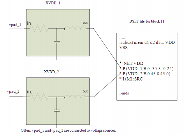
These options establish the connections of two package model instances with the power net VDD. In other words, these options will connect XVDD_1:out to pin VDD_1 of net VDD, and XVDD_2:out to pin VDD_2 of net VDD. The connections are shown in Figure 4-4.
Figure 4-4 Package Model Instances Connection with Power Net VDD
|
|
The package modeling solution is available only in the advanced EMIR (two-stage) flow (.usim_ups solver=2). |
|
|
Multiple spfipin options can be applied to the same net, each one for a particular pin. |
|
|
Any net pin without any spfipin connection is directly connected to the voltage source for the net. |
|
|

|
spfkeepcoupling is only applicable when spfactivenet or spfrcnet are enabled. |
When this option is set to on, the Virtuoso UltraSim simulator keeps the coupling capacitances as per the following criteria:
|
|
If neither of the two terminals of the coupling capacitance is specified as spfrcnet or spfactivenet, then the coupling capacitance is discarded. |
When spfkeepcoupling is set to off (default), the Virtuoso UltraSim simulator does not keep coupling capacitances while parsing parasitic files.
|
|
there is a coupling capacitance between net_A and net_B, and |
|
|
there is a coupling capacitance between net_A and net_C, and |
|
|
there is a coupling capacitance between net_C and net_D |
then the behavior will be as follows:
|
|
expand RC for net_A and net_B, and stitch lumped C on net_C and net_D. |
|
|
stitch the coupling capacitance between net_A and net_B. |
|
|
for the coupling capacitance between net_A and net_C, on the net_A side, stitch the coupling capacitance as regular coupling capacitance, and on the net_C side, connect the coupling capacitance to the pre-layout net_C. |
The coupling capacitance between net_C and net_D is not stitched. It is considered as part of total capacitances for both net_C and net_D in the DSPF file already.
The spfkeepbackslash option defines the back slash (\) symbol, used for net, instance, and other design component names, as a normal character instead of an Escape character (default is off).
tells the Virtuoso UltraSim simulator to treat the \ symbol as a normal character.
When this option is set to be 0, the software ignores negative device parameters, negative parasitic resistors, and negative parasitic capacitors in DSPF/SPF/DPF files. The default behavior is to accept negative device parameters, negative parasitic resistors, and negative parasitic capacitors from DSPF/SPF/DPF files.
Default: 1
This option enables you to specify an extra pad to a net. subnode specifies a subnode in the DSPF file. The subnode could be defined in a *|P, *|I or *|S statement. prelayout_net is the net name to which the subnode belongs.
Note: prelayout_net and subnode must have the full hierarchical path.
When spfnetpin is specified, the behavior of the Virtuoso UltraSim simulator is as follows:
|
|
If there is a subnode or pin that has the same name as the net name in *|NET statement, then the subnode or pin is shorted to the pre-layout net. |
|
|
If there is one *|P statement, the specified subnode or pin will be shorted to the pre-layout net. If there are multiple subnodes or pins, all of them will be shorted to the pre-layout net unless they are part of the hierarchical DSPF/SPEF system. |
|
|
One of the *|I or *|S statements is randomly chosen to be shorted to pre-layout net. |
usim_opt spfnetpin="NETA M1:drn"
.usim_opt spfnetpin="NETA M1:drn"
Assuming that the DSPF file contains:
UltraSim will connect M1:drn to the pre-layout net NETA. Note that the pin *|P netA is shorted to pre-layout NETA as well. If you want to disconnect this pin from the pre-layout NETA, spfdeletepin option will be needed.
Set this option to 0 to ignore the parasitic primitive diodes during stitching. When this option is set to 1, the simulator automatically detects the parasitic primitive diodes in DSPF/DPF files and stitches them accordingly.
Default: 1
tells UltraSim to ignore the parasitic primitive diodes during stitching.
The spfrcreduction option controls RC reduction during RC stitching. If spfrcreduction is on (default), the RC reduction algorithm can be applied during stitching (depending on how the RC reduction options are set). Using this option can improve simulation performance and memory. If spfrcreduction is off, RC reduction is not applied during stitching, regardless of the RC reduction option settings.
tells the Virtuoso UltraSim simulator to perform RC reduction during RC stitching if the RC reduction options, such as postl (1|2|3|4), are enabled. If postl=0, the simulator does not perform RC reduction, even it spfrcreduction=on.
This option controls how the Virtuoso UltraSim simulator handles erroneous parasitic nets. If the definition of a net in a parasitic file contains an error, you can use the spfrecover option to control how this erroneous net is stitched.
This option specifies the scale factor for parasitic capacitors (default is 1.0).
Note: The pre-layout capacitors are not affected by spfscalec.
Through the spfcrosscap=off option, UltraSim splits a cross coupling capacitor to two grounded coupling capacitors. The spfscalecrossc option instructs UltraSim to scale the value of these grounded coupling capacitors according to the following criteria:
|
|
If the terminal net of the coupling capacitor is stitched only with total C, the Ctotal value is recalculated as Cload(from dspf) - total_couplingC * (1-factor). |
Note: The spfscalecrossc option works only when the spfcrosscap option is set as off.
tells the Virtuoso UltraSim simulator to scale the grounded coupling capacitor by a factor of 0.6.
For example, assuming a cross coupling capacitor CAB exists between the nets A and B in the dspf file, and the spfcrosscap=off option is set,
*|NET A 0.010PF
*|NET B 0.015PF
CAB A B 4e-15
UltraSim splits the cross coupling capacitor CAB to two grounded coupling capacitors CA and CB. The spfscalecrossc option instructs UltraSim to scale the value of the CA and CB grounded coupling capacitors according to the following criteria:
|
|
If net A is stitched with R and C, the grounded coupling capacitor CA is scaled by a factor of 0.6, and calculated as 4e-15*0.6=2.4e-15. |
CA#### A 0 2.4e-15
|
|
If net B is stitched only with total C, the Ctotal value of net B is recalculated as 0.015e-12 - 4e-15*(1-0.6)=13.4e-15. |
CB#### B 0 13.4e-15
This option specifies the scale factor for parasitic resistors (default is 1.0).
Note: The pre-layout resistors are not affected by spfscaler.
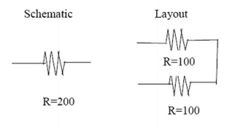
This option specifies the instance name of the resistor that has serial fingers.

These serpentine resistors are extracted as serial resistor fingers for the schematic resistor.
Note: You can specify multiple instance names using multiple spfserres options.
In the above example, X1.XRR1 is the instance name of a schematic resistor, which is represented by resistors that have two or more serial fingers. This setting ensures the correct stitching of the X1.XRR1 schematic resistor.
In the above example, X1.XRR1 is the instance name of a schematic resistor, which is represented by resistors that have two or more serial fingers. This setting ensures the correct stitching of the X1.XRR1 schematic resistor.
.usim_opt spfserresmod=model_name|subckt_name
These serpentine resistors are extracted as serial resistor fingers for the schematic resistor.
Note: You can specify multiple model names and/or subckt names using multiple spfserresmod options.
In the above example, POLY is the model name. This setting ensures the correct stitching of a schematic resistor, which is represented by resistors that have two or more serial fingers, and is an instance of the model POLY.
In the above example, POLY is the model name. This setting ensures the correct stitching of a schematic resistor, which is represented by resistors that have two or more serial fingers, and is an instance of the model POLY.
This command is applicable to both cross-coupling capacitors and ground capacitors in the pre-layout netlist. Wildcards are supported (for more information on wildcards, see Wildcard Rules ).
Skipped estimated capacitors 6
Note: This option is independent of net-based selective stitching, which includes spfrcnet and spfactive.
tells the Virtuoso UltraSim simulator to search the missing capacitors in the DSPF/SPEF file for netA. If found, the capacitors are skipped.
This option specifies whether all fingers are simulated as individual devices (spfsplitfinger=on) or all fingers are merged into one device and average values, such as width and length, are applied to the device (spfsplitfinger=off).
When .usim_emir is specified in the netlist, the default value is spfsplitfinger=on. When it is not, the default value is spfsplitfinger=off.
Specifies that all fingers should be simulated as individual devices.
This option allows the swapping of terminal1 and terminal2 of subckt during stitching. UltraSim stitching considers terminals swappable for the following primitive devices:
.subckt mosfet d g s b w1=1 l1=1
m1 d g s b nmos w=w1 l=l1
d1 s b didoe
d2 d b didoe
.ends
In this example, due to the existence of diodes, stitching considers d and s to be non-swappable. However, using the option spfswapterm, you can define d and s to be swappable for the purpose of stitching.
usim_opt spfswapterm="n1 n2 npres"
.usim_opt spfswapterm="n1 n2 npres"
tells the Virtuoso UltraSim simulator that the terminals n1 and n2 of the subckt npres are swappable terminals.
This option helps stitching of primitive elements at the top-level within the extraction scope. It is used along with spfxtorprefix. When spfxtorintop is set to yes (default), the substitution specified by spfxtorprefix is applicable not only to top-level primitive elements but also to top-level instances names.
This is an example of primitive elements at the top-level within the extraction scope. Consider that subckt s1 is extracted. This subckt is defined in the pre-layout as:
subckt in out inv
M1 out in vss vss nmos w=2 l=0.5
M2 out in vdd vdd pmos w=4 l=0.5
ends
In the extracted DSPF for subckt s1, the primitive element N1 is at the top-level of the extraction scope subckt s1. If the element name in the DSPF file for element N1 is MN1, the following option helps the stitching process find the right match:
.usim_opt spfxtorintop=yes
.usim_opt spfxtorprefix="MN N"
The spfxtorprefix option replaces substring (that is, the xtorprefix used in the RC extractor) with replace_substring. Based on the requirement that a DSPF file must be used as a HSPICE netlist file, all MOSFETs need to begin with the m symbol, all diodes with the d symbol, and so on. The hierarchical names for devices must contain leading symbols based on type, in order for HSPICE to recognize the names. Some RC extractors append a different prefix to the hierarchical name, such as MX (this prefix is considered a xtorprefix).
To match the device names in the parasitic file with the names in the pre-layout netlist file, you need to specify spfxtorprefix to be the same as what is used by the RC extractor. If it becomes necessary to change the xtorprefix substring to a different substring, specify the replace_substring option. There is no limit to the number of xtorprefices that you can specify (default is none).
usim_opt spfxtorprefix="MX_ X" spfxtorprefix="D" spfxtorprefix="R XI"
.usim_opt spfxtorprefix="MX_ X" spfxtorprefix="D" spfxtorprefix="R XI"
tells the Virtuoso UltraSim simulator to replace all instance names starting with MX_ with X, to remove the D prefix from all instance names starting with D, and to replace prefix R in all instance names with XI.
The simulator supports the following selective RC backannotation options:
This option specifies the nets to be stitched by name (default is none). All other nets are ignored and will not be stitched. Wildcards are supported and you can specify as many nets as needed.
For more information about wildcards, see "Wildcard Rules".
tells the Virtuoso UltraSim simulator to stitch the parasitics associated only with nodeA and nodeB (all other nets are not stitched).
This option allows you to specify the nets that need to be stitched as a list in a text file called file_name (only one file can be specified).
It is important to note if spfactivenet or spfactivenetfile is defined, only the specified nets are stitched. Also, you can use the acheck statement to generate the active nets file.
usim_opt spfactivenetfile=nets.tex
.usim_opt spfactivenetfile=nets.tex
nets.tex file format:
tells the Virtuoso UltraSim simulator to stitch the parasitics associated with the nets specified in the nets.tex file, and to ignore the other nets.
The spfchlevel option allows you to select the net for stitching by its hierarchy level. If the net name has a hierarchy level less than spfchlevel, the net is stitched (otherwise, only the total capacitance is added to the net node). The default is 1000 or the lowest level.
tells the Virtuoso UltraSim simulator to stitch nets that have a hierarchical level < 10.
This option specifies the net that will have its total capacitance stitched. All other parasitic components associated with this net are ignored (default is none). Wildcards are supported and you can specify as many nets as needed. All other nets will be stitched with R and C.
For more information about wildcards, see "Wildcard Rules".
tells the Virtuoso UltraSim simulator to stitch only the total capacitance of netA and to ignore other parasitics associated with netA.
This option has the same functionality as spfcnet with the exception that all the nets are specified as a list in a file named file_name. Only one file can be specified.
.usim_opt spfcnetfile=nets.tex
nets.tex file format:
tells the Virtuoso UltraSim simulator to stitch only the total node capacitance for all nets specified in the nets.tex file, and to ignore all the other parasitics associated with these nets.
This option allows you to select the net for stitching by its hierarchy level. If a net name has a hierarchy level more than or equal to spfhlevel, all the parasitics associated with the net are stitched (otherwise, only the total capacitance is added to the net node). The default is -1 or the top level.
The spfnetcmin option allows you to select the net for stitching by the value of its total node capacitance. If the total node capacitance exceeds spfnetcmin, the net is stitched. That is, all the parasitics associated with the net are stitched correctly (otherwise, only the total capacitance is added to the net node). The default is 0.0.
tells the Virtuoso UltraSim simulator to stitch parasitic resistors and capacitors for both vcc and gnd nets and to stitch all other nets with lumped capacitances.
|
|
|
If spfrcnet or spfrcnetfile is defined, only the specified nets are stitched with RC and the remaining nets in the DSPF/SPEF files are stitched with C-only. |
usim_opt spfrcnetfile=nets.tex
.usim_opt spfrcnetfile=nets.tex
nets.tex file takes the following format:
tells the Virtuoso UltraSim simulator to stitch the parasitic RC associated with the nets specified in the nets.text file, and to stitch C only for the rest of the nets in the DSPF file.
This option specifies the name of the net to be skipped, that is, all parasitic components of this net are not stitched (default is none). Wildcards are supported and you can specify as many nets as needed. All other nets will be stitched with R and C.
For more information about wildcards, see "Wildcard Rules".
Note: If multiple nets need to be specified, the nets must be placed in separate lines.
tells the Virtuoso UltraSim simulator not to stitch the parasitics associated with nodeA.
This option allows you to specify the nets to be skipped as a list in a text file called file_name. Only one file can be specified.
usim_opt spfskipnetfile=nets.tex
.usim_opt spfskipnetfile=nets.tex
nets.tex file format:
tells the Virtuoso UltraSim simulator not to stitch the parasitics associated with netA, netB, and netC.
Note: The net names in the file need to be located on separate lines.
This option allows you to skip stitching for parasitics associated with the nets that are connected to DC voltage sources. These nets usually contain a large number of parasitics, and in most types of analyses, do not affect the simulation results and can be omitted. If the stitching of power nets is important, set spfskippwnet to off. The default is on.
tells the Virtuoso UltraSim simulator to stitch the parasitics of nets connected to DC voltages.
The spfskipsignet option allows you to skip stitching for parasitics associated with signal nets (default is off).
Note: If spfskippwnet=on and spfskipsignet=on, no single nets are stitched.
tells the Virtuoso UltraSim simulator to ignore stitching parasitics for all the signal nets.
The Virtuoso UltraSim simulator prints out detailed error and warning messages generated during stitching in the netlistname.spfrpt file. In addition, a cumulative (statistics) report is printed to the screen and the log file.
Errors that cannot be corrected are issued as error messages and correctable errors are issued as warning messages. The error and warning messages are categorized according to the nature of the messages. The default number of error and warning messages for each category is 50. If you need to see more messages, increase the limit with the spfmsglimit option. You can also control the level of reporting with the spferrorreport option.
Use this option to specify the level of error reporting.
Specifies the maximum number of messages within a specified message category identifier number (STITCH-ID) to be printed in .spfrpt file. This means that the number of messages printed for a message category does not exceed the specified number limit. When a STITCH-ID is not specified, the software assigns the maximum message number limit to all message categories (STITCH-IDs).
Note: This option replaces spfmaxerrormsg and spfmaxwarnmsg. spfmaxerrormsg and spfmaxwarnmsg are internally converted to spfmsglimit.
.usim_opt spfmsglimit="10 STITCH-0010"
tells Ultrasim to print no more than 10 messages for the STITCH-0010 message category. For the other message categories, the default maximum limit of 50 messages will apply.
.usim_opt spfmsglimit="1000000"
.usim_opt spfmsglimit="5 STITCH-0020"
tells Ultrasim to print all the messages no more than 1000000 times except for the messages in category STITCH_0020 for which the software will print the messages no more than 5 times.
|
|
|
It is recommended that you go through each category reported in the .spfrpt file, understand the cause of the messages, and then limit the number of messages to be printed. This will ensure that the .spfrpt file contains only the relevant messages. |
Reading SPF file ./ring_top.spef line 32 ( 2.5% )
Reading SPF file ./ring_top.spef line 160 (19.7% )
Reading SPF file ./ring_top.spef line 285 (36.6% )
Reading SPF file ./ring_top.spef line 405 (51.2% )
Reading SPF file ./ring_top.spef line 533 (68.5% )
Reading SPF file ./ring_top.spef line 658 (85.4% )
Reading SPF file ./ring_top.spef line 777 (100.0% )
SPF Parsing: memory: 0 B total: 15.2684 MB
SPF Collect nets: memory: 0 B total: 15.2684 MB
Back annotation: memory: 131.0399 KB total: 15.3994 MB
-------------------------------------------------------------------------------
Nets | parsed 6| expanded 6| errors 0
Capacitors| parsed 485| expanded 141| stitch 70
Resistors | parsed 110| expanded 98| stitch 49
New nodes | added 90| | net coll 3
-------------------------------------------------------------------------------
nets stitched with C-only 0 nets stitched with RC 6
-------------------------------------------------------------------------------
0 errors and 13 warnings are issued (see file "my_input.spef.spfrpt")
-------------------------------------------------------------------------------
Subckt is detected with top path 1
Instance is duplicated or fingered 6
The keepparaname option allows you to choose between preserving or not preserving the names of RC elements during parsing (default is 1). The option reduces memory usage when the names are not preserved and is only applicable to designed RCs (not parasitic RCs if the parasitics are stitched). If you set usim_opt keepparaname=0, the names of RC elements are not saved, in order to reduce memory usage.
Note: You cannot probe current through an element if this setting is used.
Since keepparaname is applied during netlist file parsing, it needs to be specified before reading a netlist file. You can also switch the settings of keepparaname for different segments of the netlist file.
tells the Virtuoso UltraSim simulator not to save elements after the usim_opt keepparaname=0 statement and before the usim_opt keepparaname=1 statement (names are saved for the elements that follow usim_opt keepparaname=1).
Coupling capacitors less than cgndparse are grounded (default is 1e -18). cgndparse needs to be specified before reading a netlist file and can only be used in conjunction with usim_opt keepparaname=0 (see keepparaname for more information).
DC simulation can be time consuming for post-layout. To reduce the simulation time, you can save the pre-layout DC using usim_save and simulate the post-layout by starting DC simulation with usim_restart (Spectre syntax). This method has shown to reduce the post-layout DC simulation time significantly. The Virtuoso UltraSim simulator saves the information for all the external nodes in a file. For all internal nodes and states, if the nodes and states are registered in the solver, the information is also saved (otherwise, the simulator does not save the information in the file, and when the simulation is restarted, the unsaved internal nodes and states need to be solved again).