|
|
|||||||||
|
|
|
|
|
|
|
|
|
|
|
This chapter describes the simulation options that can be used to set the Virtuoso® UltraSim™ simulator for speed, accuracy, and functionality.
See the following topics for more information.
The Virtuoso UltraSim simulator supports Spectre® and HSPICE (registered trademark of Synopsys, Inc.) netlist file formats. The Virtuoso UltraSim simulator options can be set in a Spectre netlist file using the usim_opt command, whereas the simulator options in a HSPICE netlist file require the .usim_opt command.
You can set any number of Virtuoso UltraSim simulator options on the same usim_opt command line and also list the options in any order. These options can be set locally by using the scope option or globally (no scope).
The following scopes are supported by the Virtuoso UltraSim simulator:

|
Subcircuit instances: inst=[inst1 inst2 ...] |
|
|
Subcircuit primitives: subckt=[subck1 subckt2 ...] |
|
|
Subcircuit instance inside a subcircuit: subcktinst=[subckt1.xinst1 subckt2.xinst2 ...] |
|
|
Device model primitives: model=[model1 model2 ...] |
|
|
Model primitives inside a subcircuit: subcktmodel=[subckt1.model1 subckt2.model2 ...] |
|
|
Power network: scope=power |
|
|
Stitched network: scope=stitch |
Wildcards (*,?) can be used to match multiple scopes simultaneously (for more information about wildcards, see "Wildcard Rules" ).
Note: If the scope includes multiple entries, or contains wildcards, it must be enclosed by [] brackets.
usim_opt sim_mode=ms speed=6 postl=2
usim_opt sim_mode=a inst=i1.i2.vco1
usim_opt sim_mode=df subckt=[digital1 digital2]
.usim_opt sim_mode=ms speed=6 postl=2
.usim_opt sim_mode=a inst=x1.x2.vco1
.usim_opt sim_mode=df subckt=[digital1 digital2]
The Virtuoso UltraSim simulator also supports a common options configuration file called ultrasim.cfg, which enables you to set the simulator default options. This configuration file can be used to set netlist file, user, or site-specific Virtuoso UltraSim simulator options. Both the Spectre and HSPICE syntax options are supported in the configuration file. If the option defined in ultrasim.cfg is also defined in the netlist file, the netlist file overwrites the option. See "Virtuoso UltraSim Simulator Configuration File" for more information about configuration files.
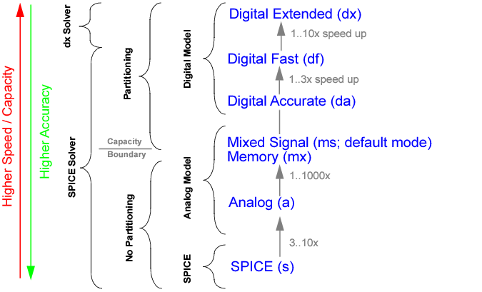
You trade-off speed and accuracy by choosing between different model and simulation abstraction levels, and by adjusting the tolerances used by the Virtuoso UltraSim simulation algorithm. The simulation mode sim_mode determines the type of partitioning and device models the Virtuoso UltraSim simulator applies to the circuit. The available modes are digital extended (dx), digital fast (df), digital accurate (da), mixed signal (ms), memory (mx), analog (a), and SPICE (s). Within each simulation mode, the speed option specifies the accuracy and determines the relative tolerance used for voltage and current calculations (valid settings are 1 to 8).
Figure 3-1 shows how simulation modes influence partitioning and device modeling. All simulation modes use the same SPICE solver. The a and s modes do not use partitioning, and the mx, ms, da, df, and dx modes use more aggressive partitioning. In addition, s mode uses SPICE models, a and ms modes use analog representative models, and df, da, and dx modes use digital representative models.
Figure 3-1 Simulation Modes
|
|
Digital Extended (dx) mode targets an accuracy of within 20% compared to s mode and is designed only for the functional verification of digital circuits. This is achieved by using a digital nonlinear current model, a constant capacitance model, and diffusion junctions with the metal oxide semiconductor field-effect transistor (MOSFET), as well as a special dx solver. |
Note: This mode is not applicable to memory or mixed signal design blocks, and may cause slow simulation speed, accuracy issues, or memory problems if used to simulate these types of design blocks.
|
|
Digital Fast (df) mode targets an accuracy of within 10% compared to s mode and is designed for the functional verification of digital circuits and memories. This is achieved by using a digital nonlinear current model for the MOSFET, and a constant capacitance model for the MOSFET, and the MOSFET diffusion junctions. A partitioning algorithm is used to provide high-speed simulation. |
|
|
Digital Accurate (da) mode is used for timing verification of digital circuits and memories, and for some PLL and mixed signal designs. da mode employs a digital nonlinear current and charge model for the MOSFET and its diffusion junctions. da mode uses partitioning and targets a simulation error of less that 5%. |
|
|
Mixed Signal (ms) mode provides the accuracy needed for analog, mixed signal, and PLL applications. It uses partitioning and an analog representative model for the MOSFET current and charge and diffusion junction. ms mode targets an accuracy within 3%. |
|
|
Memory (mx) mode provides a special simulation solution for advanced node memory designs with sensitive coupling, and internal voltage regulators. This mode supports multithreading. |
|
|
Analog (a) mode is designed for high-accuracy applications like ADC, DAC, and DC/DC circuits. It uses the same analog representative models as ms mode. It simulates the design in one partition, but provides a speed improvement of three to ten times over conventional SPICE simulation due to the analog representative model. This mode supports multithreading. |
|
|
SPICE (s) mode uses Berkeley SPICE models and is targeted to match other SPICE simulators (target error of 1%). This mode supports multithreading. |
Table 3-1 gives an overview of the Virtuoso UltraSim simulation modes, shows how they are related to device modeling, and tolerances within the simulation tool, and provides a basic understanding of what mode needs to be used for which application.
|
Timing verification of digital circuits and memories, some mixed signal (MS) designs |
||||||||||||||||||||
|
|

|
The analog representative model is the default for all simulation modes, except for s mode which uses the SPICE model |
Specifies the simulation mode that defines the partitioning and device model approach the Virtuoso UltraSim simulator applies to the circuit. Refer to Figure 3-1 for more information.
The mx, ms, da, df, and dx modes use circuit partitioning, based on ideal power supplies (dc or pwl voltage source), and apply it only to the MOSFET portion of the design. Simulation performance may be degraded as a result of using:
Solution: Use voltage regulator (VR) simulation (see Chapter 5, "Voltage Regulator Simulation" for more information).
Solution: Use voltage regulator (VR) simulation (see Chapter 5, "Voltage Regulator Simulation" for more information).
Solution: Use rvshort or the power network solver (see Chapter 6, "Power Network Solver" for more information).
Solution: Use a mode to consider inductor behavior for the circuit or use lvshort to improve performance in mx, ms, da, and df modes.
The bipolar junction transistor (BJT) or behavioral Verilog-A dominated designs cannot take advantage of circuit partitioning and other Fast SPICE technology. For these designs, Cadence recommends using s mode. For BiCMOS and latchup BJT designs, ms mode can provide a significant improvement in simulation performance.
usim_opt sim_mode=da inst=xi1.xi5.xi3
.usim_opt sim_mode=da inst=xi1.xi5.xi3
tells the simulator that subcircuit xi1.xi5.xi3 and its children are simulated in da mode, but everything else is in df mode.
The Virtuoso UltraSim simulator uses relative and absolute error tolerances while performing transient simulation. To simplify usage, it provides the high-level accuracy option speed, which allows you to customize the simulation speed and accuracy within each simulation mode. This option determines the relative convergence criterion (tol) for the current and voltage calculation.
Figure 3-2 shows how simulation speed can be set for each simulation mode to trade-off speed and accuracy.
Figure 3-2 Accuracy Settings
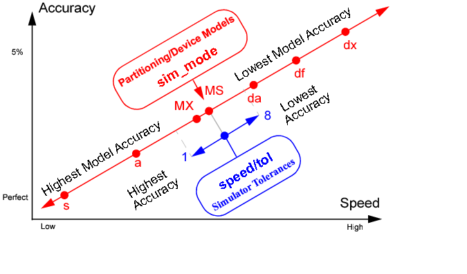
Defines the simulation speed and accuracy within the chosen simulation mode, and determines the relative tolerance for voltage and current calculations. The default value is speed=5 for all simulation modes except dx mode (default is speed=8).
Note: Cadence does not recommend using speed=7 /8 together with a or ms mode because the speed settings may not provide sufficient simulation accuracy with these modes.
Table 3-4 provides option setting recommendations for different circuit types. Cadence suggests that you start with the options in column two of the table. Column three suggests how to achieve better accuracy and speed if the recommended options do not fulfill your requirements. See "Setting Virtuoso UltraSim Simulator Options in Netlist File" for more information.
|
sim_mode=df speed=7 |
|
|||||||||
|
sim_mode=df speed=7 |
|
|||||||||
|
sim_mode=ms speed=5 |
|
|||||||||
|
sim_mode=ms speed=6 |
|
|||||||||
|
sim_mode=df speed=6 |
|
|||||||||
|
sim_mode=ms analog=2 |
|
|||||||||
|
speed=5 | 4 |
Note: May need to set maxstep_window or initial conditions to start oscillation. |
|||||||||
|
sim_mode=ms analog=2 | 4 |
|
|||||||||
|
sim_mode=ms analog=2 |
|
|||||||||
|
sim_mode=ms analog=2 | 4 |
|
|||||||||
|
sim_mode=a |
|
|||||||||
|
sim_mode=ms |
|
|||||||||
|
sim_mode=ms analog=2 | 4 |
|
|||||||||
|
sim_mode=ms |
|
|||||||||
|
sim_mode=ms |
|
|||||||||
|
sim_mode=ms |
|
|||||||||
|
sim_mode=s |
|
|||||||||
|
sim_mode=ms analog=2 | 4 |
|
|||||||||
|
sim_mode=ms Local RF block options: |
|
The Virtuoso UltraSim simulator uses circuit partitioning in higher simulation modes to improve simulation performance. Setting the analog option allows you to select between aggressive, moderate, and more conservative partitioning. The analog option applies only to the ms, da, and df modes, since the a and s modes do not use partitioning.
Controls circuit partitioning, once you have identified the analog contents of your circuit design. The higher the value of analog, the more conservative the partition algorithm.
Note: This does not apply to mx, a or s mode.
Applying analog=2 or analog=3 can slow down the simulation by forcing more conservative partitioning. To avoid slowing down the simulation, while maintaining accuracy on highly sensitive analog blocks, the analog option can be specified locally. Setting the option locally on sensitive analog blocks allows the simulator to keep the default analog level on the rest of circuit.
usim_opt analog=2 inst=x1.xpll
.usim_opt analog=2 inst=x1.xpll
Note: Analog autodetection is limited to analog-to-digital conversion (ADC) and PLL circuit designs.
Controls autodetection and promotion of analog circuits.
tells the Virtuoso UltraSim simulator to enable autodetection of analog circuits.
By default, the Virtuoso UltraSim simulator uses a pseudo-transient method of calculating the operating point. This method has been proven to handle the majority of circuits. It consists of two steps: First the power supplies are ramped and then the voltage levels are stabilized with a transient simulation. The simulator also allows you to skip the operating point calculation and to load an operating point from another simulation. In case the pseudo-transient method leads to problems, there is a pseudo-transient method available which only ramps up power supplies. The dc and dc_turbo options are used to specify the operating point calculation method.
Defines the DC simulation algorithm the Virtuoso UltraSim simulator applies to the circuit.
|
Complete dynamic operating point calculation using pseudo-transient algorithm. Strictly enforces the initial conditions (default in mx, ms, da, and df modes). |
|
|
Complete static operating point calculation using source-stepping algorithm (default in a and s modes and automatic switching to dc=1 in case of non convergence). Initial conditions are forced on to nodes by using a voltage source in series with a resistor whose resistance is 1 ohm; default Spectre® rforce value. Note: dc=3 is not recommended for ms, df, and da mode simulations. |
|
|
Complete pseudo-transient operating point (OP) calculation with damping. Suitable for designs including oscillators or designs where dc=1 causes the DC calculation to exit prematurely. |
If dc=0, the Virtuoso UltraSim simulator sets the nodal voltages as defined by .IC statements (or by the IC= parameters in various element statements) instead of solving the quiescent operating point. The DC operating points of unspecified nodes are set to 0 volts. Since all unspecified nodes will see a voltage jump at the first time step, which might cause convergence problems, it is not recommended to use dc=0.
Note: dc=0 is a Virtuoso UltraSim simulator feature and usim_opt option, and works for all netlist file formats supported by the simulator (see "Netlist File Formats" for supported formats). For simulations based on a SPICE netlist file, setting dc=0 is equivalent to specifying uic in a .tran statement.
Defines the algorithm to speed up DC simulation.
|
Enables aggressive DC simulation. Use this setting for memory and digital circuits that require: |
In most situations, the default setting (dc_turbo=0) can achieve the required DC simulation results with reasonable performance and accuracy. However, you can select a suitable value (as shown in Table 3-8 ) for dc_turbo based on the circuit type and the sensitivity for DC results. If the DC performance is slow, you can set a higher value for the dc_turbo option to speed up the simulation. Alternatively, if the DC simulation results do not have the desired level of accuracy and affect the transient simulation, you can set a lower value for dc_turbo to achieve higher accuracy while trading off performance.
Note: Avoid setting other DC options manually when using the dc_turbo option. This is because the required DC options are automatically set to an appropriate value by the UltraSim simulator based on the type of DC simulation selected using dc_turbo. In addition, setting other DC options manually can degrade the performance of dc_turbo.
tells the simulator to use moderate DC simulation algorithm.
|
Damped pseudo-transient simulation will be used in DC simulation. |
|
|
Starts the homotopy sequence from newton to ptran until DC simulation convergence is achieved. The sequence is run in the following order: newton-> gmin-> source-> dptran-> ptran. Regardless of the value you specify, UltraSim will complete the entire cycle by trying each value in this order starting from the specified value until convergence of DC simulation is achieved. For example, if you set homotopy=source, the cycle queue will be as follows: source-> dptran-> ptran->newton-> gmin. |
|
|

|
The homotopy option is recommended only for A and S simulation modes, and not for MX, MS, DA, DF, and DX modes. |
tells the simulator to use source stepping in DC simulation.
If the DC calculation does not reach any of the aforementioned conditions, the Virtuoso UltraSim simulator issues a warning message and continues the simulation. You can also use the dc_exit option to stop the simulation if a stable solution is not reached (useful when the DC calculation is important for simulation accuracy).
Controls the exit criteria for operating point calculations.
|
The simulator extends the DC calculation until a stable operating point is reached |
Controls the exit criteria for DC calculations if a stable solution is not reached.
Note: Setting dc=0 and dc=2 does not provide a stable DC solution and produces an error condition in the Virtuoso UltraSim simulator when dc_exit is set to 1 (instead use dc_exit=0 to run dc=0/2, or set dc=1/3).
The Virtuoso UltraSim simulator uses different DC methods to calculate the operating point. In general, the DC calculation is fast and does not require a progress report. When a large design is being simulated, and the DC calculation takes longer than five minutes (CPU time), the simulator prints a progress report. The report is printed for every progress_p percentage of the DC calculation time.
The Virtuoso UltraSim simulator uses a pseudo-transient method to calculate the DC operating point and generally is able to provide a stable solution. In some cases, the DC calculation does not reach a stable state. For this situation, you can use the dc_rpt_num option to print unstable nodes to a .dcr file.
Note: The unstable nodes are only reported when dc=1 or dc=2 is specified, and the DC solution is not stable when the simulator completes the DC calculation.
|
dc_rpt_num=value |
Reports values for the most unstable nodes in order of DC steady state factor (integer, unitless) |
tells the Virtuoso UltraSim simulator to print 20 unstable nodes in order of DC steady state factor.
Defines the integration method the Virtuoso UltraSim simulator applies to the circuit.
|
First-order backward Euler method (default if sim_mode=mx/ms/da/df/dx) |
|
|
Second-order gear method (automatic switching-default if sim_mode=s or a) |
|
usim_opt method=gear2
tells the simulator to use the second-order gear integration method to integrate the circuit equations.
|
|
Only dx mode supports method=euler. |
Although the speed option is all that is commonly needed to control the general accuracy of the Virtuoso UltraSim simulator, individual simulation options can be set for more fine grained control over the speed versus accuracy trade-off. You can set parameters for the universal relative tolerance tol, the absolute voltage tolerance abstolv, the absolute current tolerance abstoli, the local truncation error (LTE) trtol, and the maximum step size maxstep_window. Table 3-9 shows how these parameters depend on the speed settings.
|
1ÎĽV |
1ÎĽV |
1ÎĽV |
1ÎĽV |
1ÎĽV |
1ÎĽV |
1ÎĽV |
1ÎĽV |
|
abstoli is the absolute tolerance for currents and defines the smallest current of interest in the circuit. Currents smaller than abstoli are ignored in convergence checking and time step control.
|
abstoli=value |
Absolute tolerance (double, unit A, 0 < value < 1, default 1 pA) |
tells the simulator to use an absolute current tolerance of 10 pA for current calculations.
abstolv is the absolute tolerance for voltages and defines the smallest voltage of interest in the circuit. Voltages smaller than abstolv are ignored in convergence checking and time step control. Generally, the absolute voltage tolerance is set 106 to 108 times smaller than the largest voltage signal.
|
abstolv=value |
Absolute tolerance (double, unit V, 0 < value < 1, default 1 uV) |
tells the simulator to use a absolute voltage tolerance of 0.1 uV for voltage calculations.
maxstep_window is used to specify the maximum time step over different simulation time windows. The simulation time window is specified in the square brackets [ ] as pairs of numbers. For each pair, the first number is the start time for the simulation time window and the second number is the maximum time step for this window ending with the next time point. That is, the maxstep_window value for the simulation time window from time1 to time2 is maxstep1, time2 to time3 is maxstep2, and so forth.
Note: The time points can only use sequential double values (for example, time1 < time2 < time3).
|
maxstep1 <maxstep2...> |
|
In the following Spectre syntax example
usim_opt maxstep_window=[ 0 1n 1u 1p 10u 1e20 ]
tells the Virtuoso UltraSim simulator the maximum time step is 1n seconds during simulation time window 0 to 1u, 1p seconds during simulation time window 1 to 10u, and after simulation time 10u, the maximum time step is set to 1e20 seconds (large number indicating no maximum time step control).
In the following SPICE syntax example
.usim_opt maxstep_window=[ 100u 1p 200u 1e20 ] x1.x2
sets the maximum time step to 1p during simulation time window 100 u~200 u and 1e20 after 200 u. This setting applies only to instance x1.x2.
The relative tolerance tol is used as the universal accuracy control in the Virtuoso UltraSim simulator. Except for extremely small signals, the relative tolerance is the dominating criterion in the transient simulation. A value between 0 and 1 can be chosen; values closer to zero imply greater accuracy. tol determines the upper limit on errors relative to the size of the signal. In case you need to use a relative tolerance, which cannot be set by the high-level speed option, the tol option can be used to adjust the relative tolerance.
|
tol=value |
tells the simulator to use a relative tolerance of 0.005 for current and voltage calculation.
trtol is used in the LTE criterion, where it multiplies reltol. It it set to 3.5 by default, and should not be changed for most circuits.
|
trtol=value |
tells the simulator to use trtol=8.
relref is used as a reference for the relative convergence criteria. It defines how the relative errors should be treated based on the specified value.
|
Compares the relative errors in quantities at each node relative to the current value of that node. |
|
|
Provides the same functionality as sigglobal. In addition, compares equation residues for each node with the maximum current floating on to the node at any time in that node's history. This is the default behavior in MS, MX, DA, DF, and DX modes. |
For circuits that have difficulty converging during simulation, as a result of the design or model being used, you can use the gmin_allnodes or cmin_allnodes options to assist in convergence. The effectiveness of a particular option is dependent on the type of circuit used in the simulation. Cadence recommends trying one or both options to solve the convergence problem.
Adds the specified conductance to each node.
|
gmin_allnodes=value |
Adds the specified conductance to each node (default is zero) |
tells the Virtuoso UltraSim simulator to add a conductance of 1e-10 mho to each node.
Adds the specified capacitance to each node.
|
cmin_allnodes=value |
Adds the specified capacitance to each node (default is zero) |
tells the simulator to add a capacitance of 1 fF to each node.
The Virtuoso UltraSim simulator save (usim_save) and restart (usim_restart) features allow you to save the simulation database at a specified time point. The simulation database can be used to restart the simulation at that time point. Applications of save and restart include:
|
|
Experiment with different simulation options on sections of the circuit or on the entire circuit (for example, sim_mode, speed, or output flushing) |
For example, if the input netlist file contains the statement
.temp -10 0 25
the operating point that corresponds to .temp -10 is saved.
|
Name of the file used to save the simulation state. Multiple time points are assigned unique names. For example, filename@time1, filename@time2, and filename@time3. The saved files contain the Virtuoso UltraSim version number. (Default is <design>.save@time). |
|
|
time1, time2 |
|
|
Saves the operating point at specific intervals. For example, t=save_time1+N*save_period, N=0,1,2,... If repeat is used, subsequent save_time inputs are discarded. The saved files are named save_file@t. (Default: Save only once). |
|
Name of the file that contains the saved simulation state. (Default: <design>.simsave). |
The strobing function is used to select the time interval between the data points that the Virtuoso UltraSim simulator saves. It is enabled by setting the strobe_period option. The simulator forces a time step for each point it saves, so data is computed instead of interpolated, improving the accuracy of post simulation FFT analysis.
The strobe options are documented in the following table.
|
Sets the time interval between data points saved by the simulator |
|
|
Defines the delay between the first strobe point after strobe_start (optional, default is 0). |
usim_opt strobe_period=10n strobe_start=1u strobe_delay=5n
.usim_opt strobe_period=10n strobe_start=1u strobe_delay=5n
To address all types of simulation, ranging from high-speed digital simulation to high-precision analog simulation, the Virtuoso UltraSim simulator offers a variety of MOSFET models covering different levels of abstraction. Although the sim_mode option is what is commonly needed for controlling device modeling in the simulator, individual model options can be set for more fine grained control over the trade-off between speed and accuracy.
The Virtuoso UltraSim simulator options mos_method and mosd_method are used to control MOSFET modeling. While the BSIM SPICE model uses one set of equations for the MOSFET device, the representative models for dx, df, da, ms, mx, and a mode use different models for the core device (current and charge model), and the diffusion junctions of the MOSFET. The mos_method option determines the core device model, and the mosd_method option defines the diffusion model. If mos_method is set to SPICE, the option mosd_method is ignored. Table 3-26 gives an overview of the type of model used by each simulation mode or each mos(d)_method option.
Defines the MOSFET current and charge modeling.
|
Nonlinear digital representative current and constant capacitance charge models used in df and dx modes |
|
tells the simulator to use the nonlinear analog current and charge model for all MOSFET devices.
Defines the MOSFET diffusion junction modeling. If mos_method is set to s, mosd_method is ignored.
tells the simulator to use the nonlinear analog model for all MOSFET diffusion junctions.
Note: The mos_method and mosd_method options cannot be changed for design blocks simulated in dx mode.
Defines the MOSFET core device capacitance model in a, mx, or ms mode. A linear model can provide significant performance improvements over a nonlinear model. Cadence recommends using mos_cap only for designs that are not sensitive to nonlinear device capacitances.
|
The Virtuoso UltraSim simulator uses nonlinear MOSFET device capacitances (default) |
|
Defines the modeling of substrate current for BSIM3v3, BSIM4, BSIMSOI, and SSIMSOI devices. If s mode is used, the Virtuoso UltraSim simulator considers substrate current automatically.
Note: This option is only applicable to analog representative models (not applicable to da or df mode).
tells the simulator to activate isub during the simulation if it determines isub is large enough to be considered.
Defines the modeling of gate current for BSIM4, BSIMSOI, and SSIMSOI devices. If s mode is used, the Virtuoso UltraSim simulator considers gate current automatically.
Note: This option is only applicable to the analog representative model (not applicable to da or df mode).
|
Gate leakage current is ignored in the analog representative model (default) |
|
|
The Virtuoso UltraSim simulator controls the memory usage for table models. |
tells the Virtuoso UltraSim simulator to control the memory usage of table models.
usim_opt generic_mosfet=device_master_name
.usim_opt generic_mosfet=device_master_name
Note: device_master_name is a string.
Defines diode modeling in the Virtuoso UltraSim simulator, with an emphasis on juncap modeling.
Note: For juncap, the default is s for s mode and a for a/ms/mx/da/df modes.
usim_opt diode_method=a model=d
.usim_opt diode_method=a model=d
tells the simulator to use the default model if d is a juncap model (if d is a regular diode, the diode_method option is ignored by the simulator).
The dcut option deletes all or selected diodes in the netlist file. This is helpful in designs with large amounts of diodes, where the diodes do not have an impact on the function of the design (for example, input protection diodes). The dcut option applies to the following diode types: diode, dio500, juncap200, juncap, juncap_eldo, dst, and hisim_diode.
tells the simulator to delete all the diodes in x1.x2 and all its subcircuits.
Note: minr is only valid in Spectre format.
tells the Virtuoso UltraSim simulator to short all resistors <1.0e-4 in all models.
The Virtuoso UltraSim simulator uses representative digital models in df and da mode. These models are generated in the beginning of the simulation, stored in the *.lsn file, and can be reused using the model_lib option. The .lsn file gets updated when changes in the devices, voltage supplies, or process variations occur. The voltage range used for building the models is automatically chosen by detecting the value of the highest power supply and is used for all device models. The generated models are valid over at least 2 times the given voltage range.
In designs with low and high voltage devices, where the voltages differ by an order of magnitude (that is, 2 V/10 V), using higher voltage to build the low voltage device models can lead to a significant modelling error. In this case, it is recommended to use the lower voltage for the low voltage devices and the higher voltage for the high voltage devices. To specify the voltage range, the Virtuoso UltraSim simulator provides the vdd option, which can be applied to devices, subcircuits, and instances.
Defines the maximum voltage for the generation of digital representative models (da and df mode only).
|
vdd=value |
usim_opt vdd=2.1 model=[nf pf]
.usim_opt vdd=2.1 model=[nf pf]
The Virtuoso UltraSim simulator uses partitioning to speed up the simulation in df, da, mx, and ms modes. Partitions are built by putting all channel-connected devices into the same partition, and by cutting between capacitive coupled nodes. This approach works fine for digital circuits, memories, and most mixed signal applications.
The canalog and canalogr options determine the thresholds for identifying analog coupling capacitances. Any capacitor larger than canalog, and its ratio to the total capacitance at either node is greater than canalogr, is treated as an analog capacitance. This same threshold applies to nonlinear capacitances (for example, MOSFET Cgd). Setting canalog and canalogr lower can lead to more stable and accurate results, but usually increases run time. Setting it too high can cause less accurate results when heavy coupling occurs.
Defines the absolute threshold value for identifying analog coupling capacitances in df, da, and ms modes (does not apply to a, s, and mx mode).
|
canalog=value |
Maximum capacitance value (double and unit F) The canalog default value is dependent on the value of the analog option:
|
Defines the relative threshold value for identifying analog coupling capacitances in df, da, and ms modes (does not apply to a, s, and mx mode).
|
canalogr=value |
Relative threshold value (double, unit F, and 0 < value < 1) The canalogr default value is dependent on the value of the analog option:
|
The Virtuoso UltraSim simulator supports the simulation of inductances. Simulations including inductors can be more time consuming. Sometimes it is helpful to short all inductors in a netlist file, to do a first functional verification. The options lshort and lvshort provide the opportunity to short inductors in the signal paths or power supply lines.
Defines the threshold value for inductor shorting in signal nets. Inductors smaller than value are shorted.
|
lshort=value |
tells the simulator to short all inductors less than 1ÎĽH in signal nets.
Defines the threshold value for inductor shorting in power nets. Inductors smaller than value are shorted.
|
lvshort=value |
tells the simulator to short all inductors less than 1ÎĽH in power nets.
|
wf_format=sst2 |
SST2 format (SimVision and ViVA waveform viewers; trn/dsn; default) |
|
wf_format=fsdb |
|
|
wf_format=psf |
|
|
wf_format=wdf |
|
|
wf_format=psfxl |
|
The Virtuoso UltraSim simulator is able to write files of unlimited size in SST2 and FSDB format, whereas PSF and WDF formats are limited to a maximum of 2 GByte files. Use the wf_maxsize option to split waveform files.
Data compression varies between the formats: SST2 - high, FSDB and WDF - medium, and PSF - low. It is recommended that you use SST2 format for larger circuit designs.
The Virtuoso UltraSim simulator writes waveform files into the current directory. To enable other Cadence tools to read Virtuoso UltraSim PSF format, create a raw directory using the Virtuoso UltraSim simulator -raw command line option
In the following Spectre syntax example,
tells the simulator to generate a waveform file in PSF format.
In the following SPICE syntax example,
.usim_opt wf_format=[psf sst2]
tells the simulator to generate two waveform files, one in PSF format and the other in SST2 format.
The Virtuoso UltraSim simulator allows you to specify after what period of transient simulation time the waveform data is printed into the output waveform file, determined by the option dump_step. Its default value is 10% of trend. You can also enter the interactive mode with Control-C, and use the interactive command flush any time.
Defines the time period after which the waveform data is printed into the output waveform file.
|
dump_step=value |
Time period (double, unit s, 0 < value, default 10% of tend) |
tells the simulator to print waveforms every 10 ns of transient time into the output waveform file.
There are specific waveform formats (for example, psfbin or psfascii) with 2 Gigabyte file size limitations. The wf_maxsize option is used to limit the maximum size of a waveform output file. If this option is not set, and the output file exceeds its size limit, the simulation stops.
|
wf_maxsize=[number] |
Note: If a circuit.sp file and PSF waveform format is used, the following output file list is generated: circuit.tran, circuit_1.tran, circuit_2.tran, circuit_3.tran ... circuit_n.tran.
The accuracy for voltage and current waveforms, and the time resolution in the output waveform file can be set individually, depending on the application. The Virtuoso UltraSim simulator provides the absolute criteria wf_abstoli, wf_abstolv, and wf_tres, and the relative tolerance wf_reltol.
Enables customized filtering of waveform data. In default ms mode, the Virtuoso UltraSim simulator uses moderate filtering (wf_filter=2) to minimize waveform file size without losing accuracy for standard applications. For sensitive analog designs and small signal amplitudes, no filtering (wf_filter=0) or conservative filtering (wf_filter=1) may be required. Greater waveform file size reduction for large digital and memory designs can be achieved using wf_filter=3 and wf_filter=4.
|
Conservative waveform data filter for analog circuits with small signal amplitudes (default in a mode) |
|
|
Moderate waveform data filter (default in ms, mx, da, and df modes) |
|
tells the simulator not to filter the waveform data.
|
wf_reltol=value |
Defines the time resolution and time unit in the output waveform file.
|
wf_tres=value |
tells the simulator to use a time resolution and unit of 10 ps in the output waveform file.
Defines the absolute voltage resolution in the output waveform file.
|
wf_abstolv=value |
tells the simulator to use a voltage resolution of 0.01 mV in the output waveform file.
Defines the absolute current resolution in the output waveform file.
|
wf_abstoli=value |
tells the simulator to use a current resolution of 1 pA in the output waveform file.
Table 3-48 gives an overview of the default values for wf_reltol, wf_abstolv, and wf_abstoli dependent on the wf_filter option used.
Enables you to specify the type of number representation that should be used in the waveform output files. The number representation can be of double or float types. This option applies to SST2, PSF, PSFASCII, FSDB, and WDF waveform formats.
Note: double number representation provides higher precision but results in larger output file size.
|
Waveform data is written using the float number representation (default). |
|
|
Waveform data is written using the double number representation. |
tells the UltraSim simulator to switch to double number representation when printing data in the waveform output files.
Controls the appearance of a hierarchical node name in the waveform database.
|
Includes the following formats in the waveform database: x1.x11.n1 and x1.x11.m1:1 |
|
|
Includes the following formats in the waveform database: x1.x11.n1 and x1.x11.m1:1_$flow |
|
|
Includes the following formats in the waveform database: v(x1.x11.n1) and i1(x1.x11.m1) |
The option model_lib specifies the name of the model library file that stores all digital representative models (the model library is always given a .lsn extension). The default name for the model library is the netlist filename. For example, suppose the netlist filename is netlist.sp. Then the model library file would be called netlist.lsn. It is recommended to keep the path of the file relative to the working directory.
Defines the library file used for digital representative models (da and df mode only).
|
model_lib=filename |
Filename (default netlist.lsn) |
In the following Spectre syntax example
usim_opt model_lib=mod.lsn
tells the simulator to use the model file mod.lsn out of the netlist file directory.
In the following SPICE syntax example
.usim_opt model_lib="/home/user/ms2/mod.lsn"
tells the simulator to use the model file /home/user/ms2/mod.lsn.
The Virtuoso UltraSim simulator allows you to customize how warning messages are handled by the simulator. The number of messages per warning category can be limited globally for all warnings (usim_opt warning_limit) or individually for each category (usim_report warning_limit). When the specified category limit is reached, the simulator notifies you that the warning messages are no longer being displayed. Dangling and floating node warnings are controlled by the number of reported nodes.
|
warning_limit=value |
A limit can also be applied to a specific warning category using the usim_report warning_limit command.
tells the simulator to print out 10 warnings per warning category.
A dangling node, often the result of a design or netlist file problem, is only connected to one device or element (a node in a circuit requires a minimum of two connections). The warning_limit_dangling command is used to define the maximum number of listed dangling nodes (default is 50).
usim_opt warning_limit_dangling=100
.usim_opt warning_limit_dangling=100
tells the simulator to print out 100 dangling nodes.
A floating node is an input node (that is, a MOSFET gate) which is not driven by an element or device, and has no DC path to ground. The Virtuoso UltraSim simulator automatically connects floating nodes through a 1e12 ohm resistor (gmin_float=1e-12) to ground. The warning_limit_float command defines the maximum number of listed floating nodes (default value is 50). The floating nodes are listed in two categories: 1) Nodes connected to MOSFET or JFET gates and 2) nodes not connected to any device gates.
usim_opt warning_limit_float=100
.usim_opt warning_limit_float=100
tells the simulator to print out 100 floating nodes.
A nearly floating node is a node with a high resistive path to a driver or ground. A common example is the unconnected substrate of a MOSFET. The warning_limit_near_float command defines the maximum number of listed nodes which have a weak DC path to ground (default value is 50). These nodes are listed in two categories: 1) Nodes connected to MOSFET or JFET gates and 2) nodes not connected to any device gates.
usim_opt warning_limit_near_float=100
.usim_opt warning_limit_near_float=100
tells the simulator to print out 100 nodes with a weak DC path to ground.
usim_opt warning_limit_ups=100
.usim_opt warning_limit_ups=100
tells the simulator to print out 100 large resistors in power net.
Allows you to filter out specific nodes related to dangling, floating, and nearly-floating nodes from warning messages. Wildcards can be used to define these nodes (see "Wildcard Rules" for more information).
In the following Spectre syntax example
usim_opt warning_node_omit=[x1.x23.uncon20]
tells the Virtuoso UltraSim simulator to exclude the x1.x2.uncon20 node from the node list of dangling, floating, and near-floating warning messages.
In the following SPICE syntax example
.usim_opt warning_node_omit=[x3.x*]
tells the simulator to exclude all nodes under the x3.x* hierarchy from the node list.
.usim_opt warning_node_omit=[x1.x23.uncon20 x3.x*.uncon*]
tells the simulator to exclude the x1.x23.uncon20 node and all nodes matching x3.x*.uncon* from the node list.
The Virtuoso UltraSim simulator allows you to start the simulation at a user-defined time using the sim_start option.
tells the Virtuoso UltraSim simulator to start the simulation at 10 ns.
These options are used to print out simulation progress reports to a standard output display device (stdout) or log file during transient simulation. If the options are not specified, the Virtuoso UltraSim simulator prints out progress reports at 10% intervals during the transient simulation, or every two hours, whichever occurs first.
To define the time interval (in minutes) the simulator prints out the transient simulation progress report to a stdout or log file, use
Note: Any value for time, other than a whole number, is ignored and the default is used.
To define the interval (in transient percentage) the simulator prints out the transient simulation progress report to a stdout or log file, use
Note: This option can also be used to specify the DC progress report.
In the following Spectre syntax example
tells the simulator to print out a progress report every 5 minutes.
In the following SPICE syntax example
.usim_opt progress_t=10 progress_p=5
The model_progress_t option defines the time period the Virtuoso UltraSim simulator uses to print out a progress report during model building (minimum time value is one minute).
|
model_progress_t=value |
Specifies time period required to print out the model building progress report. |
This option allows you to print locally and globally defined simulation options, so you can identify which simulation options are being used for specific blocks in the circuit design. The simulation options are printed to a Virtuoso UltraSim report file (.usim_opt_rpt) and also appear as a message in the log file (.ulog).
The .ulog file contains the following lines which indicate the start and stop time points for the local options:
Starting reporting local options in: <filename>
Ending reporting local options
The local simulation options are located under the .usim_opt scope heading and the global simulation options are located under the Top Level Options heading in the report file.
|
0 - Report is not generated (default). 1 - Detailed report containing subcircuits and/or instances is generated. 2 - Complete report listing all of the instances is generated. |
|
|
Defines the hierarchical depth [optional]. The default value is the maximum hierarchical depth of the circuit design. If block_depth=0, only the global option set is printed. |
usim_opt sim_mode=da analog=2 speed=4 inst=[X1]
usim_opt sim_mode=s inst=[MNIV1]
.usim_opt sim_mode=da analog=2 speed=4 inst=[X1]
.usim_opt sim_mode=s inst=[MNIV1]
The Virtuoso UltraSim simulator generates the following <filename>.usim_opt_rpt file:
***************************************************************************
.TITLE 'This file is :./usim.usim_opt_rpt
Options at all the levels are printed
**********************************************************************
**********************************************************************
.usim_opt scope:
MNIV1 (n3p3fets)
The Virtuoso UltraSim simulator node_topo_report option allows you to copy node topology analysis results into the following types of ASCII report files:
|
|
Floating node (.floating_rpt file extension) |
|
|
Nearly floating node (.weak_floating_rpt) |
|
|
Dangling node (.dangling_rpt) |
The default setting is node_topo_report=0, where node topology report files are not generated by the simulator (initial node topology warnings are still copied into the log files).
tells the Virtuoso UltraSim simulator to generate node topology reports for floating, nearly floating, and dangling nodes. If your netlist file is named netlist.sp, the simulator creates netlist.weak_floating_rpt, netlist.floating_rpt, and netlist.dangling_rpt files.
Defines the resistor value used for grounding floating nodes (default gmin_float value is 1e-12).
Because Virtuoso UltraSim is a Fast SPICE simulator, it is able to handle large designs due to its true hierarchical approach. The basic idea is to consider subcircuits which are the same and see the same stimuli as one subcircuit. This allows a significant performance improvement compared to flat simulation. There is a certain overhead used for traversing the hierarchy. For circuits where each subcircuit shows different behavior, it can be advantageous to trade memory usage for speed, by flattening the circuit hierarchy.
With the exception of the SPICE and Analog modes, the Virtuoso UltraSim simulator uses an autodetect mode to detect the circuit hierarchy by default. If you want to flatten this circuit, you can use the hier command. Even with a flattened netlist file, the Virtuoso UltraSim simulator uses the same simulation engine.
Defines the hierarchy approach the Virtuoso UltraSim simulator applies to the circuit.
tells the simulator to flatten the entire circuit.
Devices, which are operated out of the model range they were designed for, can lead to a significant simulation error, as well as to convergence problems. The Virtuoso UltraSim simulator provides an error message if it find such devices. If this problem occurs, and you want to continue the simulation, the option strict_bin can be set to use the closest model bin for out-of-range devices.
Defines the model binning approach in the Virtuoso UltraSim simulator.
tells the simulator to give a warning and uses the closest model bin for models out of model range.
Allows to disable element compaction
tells the simulator to not perform element compaction.
The Virtuoso UltraSim simulator uses logic waveforms for the following statements: .lprint/.lprobe, usim_ta, and usim_nact. You can set the threshold voltages by using arguments with each of the aforementioned statements or by defining the threshold voltages using the vl and vh options. These options can be set globally for the entire circuit or locally for an instance or subcircuit.
Note: Local settings overwrite global settings.
Defines the threshold value for logic 1. Any signal above this value is considered 1.
|
vh=value |
High threshold voltage (double, unit V). If not specified, the default value is 70% of vdd. If the vdd option is not specified, vh is defined as 70% of the highest voltage supply in the circuit. |
.usim_opt vh=1.2 inst=XDIGITAL
tells the Virtuoso UltraSim simulator for block XDIGITAL to consider signals above 1.2 v to be logic 1, and for all signals outside block XDIGITAL, use 2.3 v as the threshold for logic 1.
Defines the threshold value for logic 0. Any signal below the value is considered 0.
|
vl=value |
Low threshold voltage (double, unit V). If not specified, the default value is 30% of vdd. If the vdd option is not specified, vl is defined as 30% of the highest voltage supply in the circuit. |
tells the simulator to print a logic 0 for all signal values below 0.9 v.
The default hierarchical delimiter is a single period (.) but can be changed by setting the hier_delimiter option.
|
|
To define the delimiter as " or \, the Escape symbol is required (for example, usim_opt hier_delimiter="\""). |
The Virtuoso UltraSim simulator, by default, does not allow you to use node and element names containing a period (.) because this symbol is reserved as a hierarchical delimiter.
In special cases, a period may be used as a hierarchical delimiter and as part of a node name. You can use hiernode_lookup=2 to enable the Virtuoso UltraSim simulator to consider the period as part of a node name.
For example, a probe or measure statement can be applied to x0.x1.x2.nd, where x0.x1 is the hierarchical instance name and x2.nd is the node name. If hiernode_lookup=2 is used, the Virtuoso UltraSim simulator automatically identifies the hierarchical instance name and reserves x2.nd as the node name.
|
|
Works even if the hierarchical delimiter is changed. For example, x1/x2/x3/net5, where the hierarchical delimiter is /. |
|
Period (.) cannot be used as part of node names (default) |
|
Using Verilog-A modules or controlled sources to model gate leakage effects in MOSFET devices may cause conservative partitioning and slow simulation speed. The Virtuoso UltraSim simulator search_mosg option allows you to select more aggressive partitioning and a faster simulation speed.
Circuit designers often want to simulate the effects of parasitic bipolar junction transistor (BJT) devices formed in the triple well CMOS process. Including these transistors in the simulation may result in conservative partitioning and slow simulation speed. The parasitic_bjt option allows you to control the way the Virtuoso UltraSim simulator handles the parasitic BJT devices, resulting in much faster simulation speed.
|
Detect parasitic vertical PNP BJT devices and invoke aggressive partitioning |
|
In the following Spectre syntax example
In the following SPICE syntax example
tells the simulator to cut away all the parasitic vertical PNP BJT devices.
You can define the handling of duplicate subcircuits by using the duplicate_subckt option in the netlist file. The following settings can be specified:
|
Stops the simulation upon encountering a duplicate subcircuit and issues an error message. (Default) |
|
|
duplicate_subckt=warning |
|
|
duplicate_subckt=ignore |
|
Note: The behavior of this option is the same as opt1 options duplicate_subckt=error|warning|ignore Spectre option. If multiple options are defined, the last definition overwrites the previous definitions.
|
|
Setting duplicate_subckt to |
.usim_opt duplicate_subckt=error
will stop the simulation and issue an error message if duplicate subcircuits are detected.
|
|
Setting duplicate_subckt to |
.usim_opt duplicate_subckt=warning
will use the last definition of the subcircuit, override all previous subcircuit definitions, and issue a warning message.
|
|
Setting duplicate_subckt to |
.usim_opt duplicate_subckt=ignore
will use the last definition of the subcircuit, override all previous subcircuit definitions, and not issue any message.
You can define the handling of duplicate ports in a subcircuit using the duplicateports option in the netlist file. The following settings can be specified:
Note: The behavior of this option is the same as opt1 options duplicateports=error|warning|ignore Spectre option. If multiple options are defined, the last definition overwrites the previous definitions.
|
|
Setting duplicateports to |
.usim_opt duplicateports=error
will stop the simulation and display an error message if duplicate ports are detected in a subcircuit.
|
|
Setting duplicateports to |
.usim_opt duplicateports=warning
will treat the duplicate ports as one port and display a warning message.
|
|
Setting duplicateports to |
.usim_opt duplicateports=ignore
will treat the duplicate ports as one port but will not display any message.
You can define the handling of duplicate instance definitions by using the duplicateinstance option in the netlist file. The following settings can be specified:
|
Stops the simulation upon encountering a duplicate instance and issues an error message. (Default) |
|
Note: The behavior of this option is the same as opt1 options duplicateinstance=error|warning|ignore Spectre option. If multiple options are defined, the last definition overwrites the previous definitions.
|
|
Setting duplicateinstance to |
.usim_opt duplicateinstance=error
will stop the simulation upon encountering a duplicate instance and issue an error message.
|
|
Setting duplicateinstance to |
.usim_opt duplicateinstance=warning
will use the last definition of the instance, override all the previous instance definitions, and issue a warning message.
|
|
Setting duplicateinstance to |
.usim_opt duplicateinstance=ignore
will use the last definition of the instance, override all the previous instance definitions, and will not issue any message.
The Virtuoso UltraSim simulator resolves bus signals into individual signals when reading Verilog netlist files (.vlog). The buschar option and either <> or [] is used to set the bus notation. The exception is bus notation for vector and vcd stimuli which is set using vector and vcd options (see Chapter 11, "Digital Vector File Format" and Chapter 12, "Verilog Value Change Dump Stimuli" for more information).
tells the Virtuoso UltraSim simulator to use <> as the notation for bus signals read from the structural Verilog netlist file.
The Virtuoso UltraSim simulator can support name mapping for bus nodes when instantiating analog cells in a structural Verilog netlist file. Bus node mapping between the structural Verilog netlist file and analog cell is based on the order of the nodes. To resolve bus signals into individual signals in the analog netlist file, the vlog_buschar option is used to set the bus notation.
.usim_opt vlog_buschar="front_bus_symbol*end_bus_symbol"
where asterisk (*) is a keyword and the default bus symbol is [] (square brackets). The front_bus_symbol and end_bus_symbol arguments define the starting and ending letters of bus notation, respectively.
Structural Verilog netlist file:
add4 u1 ( .a ({ net1, net2, a1, a2 }), .sum ({ sum1, sum0 }), .vdd(VDD3),
.vss(VSS_DIG) );
.subckt add4 a_3 a_2 a_1 a_0 vdd vss sum_1 sum_0
tells the Virtuoso UltraSim simulator to map the net1, net2, a1, and a2 nodes in the Verilog netlist file to a_3, a_2, a_1, and a_0 in the analog netlist file, as well as sum1 and sum0 to sum_1 and sum_0.
Structural Verilog netlist file:
tells the simulator to map the n[2], n[1], and n[0] nodes in the Verilog netlist file to a<2>, a<1>, and a<0> in the analog netlist file.
Structural Verilog netlist file:
ram i0 ( .A(Addr), vdd(VDD3) );
subckt ram A7 A6 A5 vdd A4 A3 A2 A1 A0
tells the simulator that the A4 through A0 analog signals are not recognizable as bus nodes because the vdd node ends the bus node definition.
When invoking an analog cell using SPICE syntax from a structural Verilog instance, the redundant ports of the SPICE cell are connected to dummy nodes if the Verilog instance has fewer ports than the SPICE cell. If the power nets (for example, vdd and vss) are only defined in the SPICE subcircuit, and not the Verilog instance, they are also connected to dummy nodes.
Note: For the Virtuoso UltraSim simulator, the local node always overwrites the global node.
For example, in the Spectre netlist file
Structural Verilog netlist file:
The vdd and vss nodes cannot be connected to the power net, even if they are declared global nodes in the netlist file.
The vlog_supply_conn option is used to connect to
This option is used to connect a dummy node to either the global or internal node of the Verilog instance. The port names in the analog netlist file are specified using portname1, portname2, ... and node1, node2, ... is used to specify the internal or global node names of the Verilog instance.
The option can be applied locally to a Verilog module or instance and is set the same as the other Virtuoso UltraSim simulator local options (see Examples below for more information). The Verilog module and instance can be regarded as a subcircuit and instance when setting the local options. This option is also valid for lower hierarchical level instances.
Note: The vlog_supply_conn option has no effect when the port of a subcircuit in the analog netlist file is not a dummy node, and the port is connected to a signal in the Verilog netlist file.
In the following Verilog netlist file example
.usim_opt vlog_supply_conn=[vdd global_vdd vss global_vss]
The global_vdd node is connected to vdd in the add subcircuit of instance u1, and the global_vss node is connected to vss.
In the next Verilog netlist file example
tells the Virtuoso UltraSim simulator that the analog netlist file is the same as the one used in the previous example. The vdd and vss nodes of the Verilog instance u1 are not dummy nodes, so they are not connected to the global node by the simulator.
In the following Verilog netlist file local option example
.usim_opt vlog_supply_conn=[vdd global_vdd vss local_vss] xdigital.verilog.u1
.subckt xor in1 in2 out vdd vss
.subckt nand4 in1 in2 in3 in4 out vdd vss
tells the simulator vdd and vss of nand4 for Verilog instance u2 are still connected to dummy nodes because the option is local and is only applied to Verilog instance u1. Also, vdd and vss of xor for instance u1 are connected to the global_vdd (global) and local_vss (local) nodes in the Verilog netlist file, respectively.
Use the skip option to disable a circuit block simulation.
|
The Virtuoso UltraSim simulator includes the circuit block in the simulation (default). |
|
In the following Spectre syntax example
tells the Virtuoso UltraSim simulator to disable the x0.x1 circuit block simulation.
In the following SPICE syntax example
.usim_opt skip=1 subckt=op_amp
tells the simulator to disable the simulation for all instances of the op_amp subcircuit.
Use to control the preserve setting of .probe statements. If probe_preserve is set to all, the simulator applies preserve=all to all .probe statements.
Note: When set to all, the probe_preserve option overrides preserve=none|all specified in .probe statements. It does not override preserve=port.
|
Does not have any impact on .probe statements (default). |
|
|
Applies preserve=all to all .probe statements. |
In the following Spectre syntax example
tells the Virtuoso UltraSim simulator to apply preserve=all to all .probe statements in the netlist.
In the following Spectre syntax example
tells the Virtuoso UltraSim simulator to apply preserve=all to all .probe statements in the netlist.
By default, the substrate forward-bias check (usim_report chk_substrate) reports all MOSFET substrate models in the report file. If the default_chk_substrate option is set to no, the UltraSim simulator generates a report that contains only the MOSFET substrate models that are specified using the model argument of the chk_subsrate option (see Substrate Forward-Bias Check ).
Table 3-71 default_chk_substrate Options
|
Causes the usim_report chk_substrate option to include all MOSFET substrate models in the report (default). |
|
|
Causes the usim_report chk_substrate option to include only those MOSFET substrate models in the report that are specified using the model argument of the chk_substrate option. |
usim_opt default_chk_substrate=no
|
The Virtuoso UltraSim simulator does not print cut nodes into a file (default) |
|
|
The simulator prints all cut nodes into a .nodecut file |
|
The simulator does not print cut elements into a file (default) |
|
|
The simulator prints all cut elements into a .elemcut file |
Determines whether to enable or disable the .print command.
|
Enables the .print command (Default). |
|
|
Disables the .print command. However, the signals in the .print statements are saved in the waveform file. |
Controls text wrapping in circuit check reports created by Virtuoso Ultrasim Simulator.
The error message limit specified using the dcheck_err_limit option will impact the following design checks:
usim_opt dcheck_err_limit=1000
.usim_opt dcheck_err_limit=1000
This option limits the number of error messages that will be printed in the reports generated by the power checking (pcheck) commands except pcheck title hotspot (Hot Spot Node Current check). The default value is 10000.
The error message limit specified using the pcheck_limit option will impact the following power checks:
tells the UltraSim simulator to limit the number of error messages in the reports generated by the power checks except pcheck title hotspot to 1000.
This option limits the number of error messages that will be printed in the reports generated by the timing analysis (usim_ta) commands. The default value is 10000.
This check affects the following timing analysis commands:
usim_opt usim_ta_err_limit=1000
.usim_opt usim_ta_err_limit=1000
When set to 0 (default), the UltraSim simulator prints the condition expression along with the populated parameter values. When set to 1, only the parameter values are printed.
.usim_opt dcheck_cond_report=1
tells the UltraSim simulator to print only the parameter values and not the condition expression.
The usim_trim option can be used to change the values of resistors and capacitors, and the length, width, and threshold voltage of a MOSFET device, without modifying the netlist file.
|
|
The usim_trim option does not work with stitched dspf or spef flows |
|
|
Only MOSFET device lengths, widths, and threshold voltages can be changed (use the delvto device model parameter to adjust threshold voltages) |
In the following Spectre syntax example
usim_trim instance=x1.x2.cap5 value=3f
tells the Virtuoso UltraSim simulator to change the value of instance x1.x2.cap5 to 3f (Fahrenheit).
In the following SPICE syntax example
.usim_trim instance=x1.x2.x3.res5 value=1k
tells the simulator to change the value of instance x1.x2.x3.res5 to 1k (ohms).
.usim_trim instance=x1.x2.mp00 w=10e-5 l=5e-5
tells the simulator to change the width of instance x1.x2.mp00 to 10e-5 meters and length to 5e-5 meters.
.usim_trim instance=x1.mn1 w=1.0e-6
tells the simulator to change the width of instance x1.mn1 to 1.e-6 meters.
Spectre syntax is not supported.
|
Specifies the port name of the instance whose original connection is to be disconnected. The syntax to define a port of an instance is instancename.portname where . is the hierarchical delimiter. For example, the port vdd of instance X1 is defined as X1.vdd. The port can be defined explicitly or implicitly in a global statement. |
|
|
Specifies the port name of the subckt whose original connection is to be disconnected. This is applicable to all the instances of the subckt. As in the case of instport, the port can be defined explicitly or implicitly. The syntax to specify the port vdd of all the instances of subckt inv is inv/vdd where / is the hierarchical delimiter. |
.reconnect instport=x1.p node=vcc
Suppose that p is an explicit port of x1 and the hierarchical delimiter is ., this command disconnects the original connection of port p of x1 and reconnects a top-level node vcc to instance x1's port p.
.reconnect instport=x1/vdd node=vcc
Suppose that vdd is defined as a global node and / is the hierarchical delimiter, this command reconnects a top-level node vcc to the global node vdd inside instance x1, including all the hierarchies inside x1. The connection of vdd in other blocks remains unchanged.
.reconnect subcktport=pump.out node=vcc
Suppose that out is an explicit port of subckt pump and it has three instances: xpump1, xpump2, and xpump3, this command tells UltraSim that all instances' port out, that is, xpump1.out, xpump2.out, xpump3.out, have to be disconnected from their original connections and reconnected with vcc.
.reconnect instport=x1.x2.p node=x3.x4.netA
Suppose that port p is an explicit port, this command tells UltraSim to reconnect node x3.x4.netA with the port p of instance x1.x2 and disconnect the original connection of x1.x2.p.
.usim_opt switch_cmiumi_source=1
Enables the simulator to use CMI models for all the source elements.
|
use_veriloga=1 [inst=[instance_list]] [subckt=[subckt_list]] |
|
|
Uses the verilogA model for the instance names specified in the inst list or selects the verilogA model specified in the subckt list. If the inst or subckt list is not specified, the verilogA model is used for all instances. Wildcard character * is supported in instance names and verilogA model names. |
|
|
use_veriloga=0 [inst=[instance_list]] [subckt=[subckt_list]] |
|
|
Uses subcircuit definition for the instance names specified in the inst list or selects the subcircuits listed in the subckt list. If the inst or subckt list is not specified, the subcircuit definition is used for all instances. Wildcard character * is supported in instance and subcircuit names. |
|
usim_opt use_veriloga=1 inst=[abc*]
.usim_opt use_veriloga=1 inst=[abc*]
Uses the verilogA model for all instance names that begin with the string abc.
usim_opt use_veriloga=1 inst=[abc xyz ]
.usim_opt use_veriloga=1 inst=[abc xyz ]
Uses the verilogA model for abc and xyz instance names.
usim_opt use_veriloga=0 inst=[abc]
.usim_opt use_veriloga=0 inst=[abc]
Uses the subcircuit definition for abc instance name.
usim_opt use_veriloga=1 subckt=[abc xyz]
.usim_opt use_veriloga=1 subckt=[abc xyz]
Uses the verilogA models abc and xyz.
usim_opt use_veriloga=0 subckt=[abc*]
.usim_opt use_veriloga=0 subckt=[abc*]
Uses the subcircuit names that begin with the string abc.
Uses the verilogA model for all instances.
The default values for the Virtuoso UltraSim simulator options are listed below in Table 3-79. The majority of these options are listed in the Simulation Options section of the output log file. The default values may vary for different versions of the simulator.
|
1(df/da/ms); ignored(a/mx/s) |
|
|
be(df/da/mx/ms); gear2(a/s) |
|
|
1(df/da/ms); 0(a/mx/s) |
|
|
df(df), da(da), a(ms/mx/a), s(s) |
|
|
df(df/da), a(ms/mx/a); ignored(s) |
|
|
Juncap: a(df/da/ms/a) s(s); other diodes: s(df/da/ms/a/s) |
|
|
1(df/da/ms/mx); 3(a/s) |
|
|
. (period) |
|
|
5 m(dt/da); |
|
|
2(df/da/ms); 1(a); 0(s) |
|
|
|
The df abbreviation stands for global df mode, da for global da mode, ms for global ms mode, mx for global mx mode, a for global a mode, and s for global s mode. |
|
|
The Virtuoso UltraSim simulator automatically promotes analog from 1 to 2 when simulating a small design (that is, a design with less than 200 active devices). The analog option is ignored in global a/s mode. |