4
Technology File Layer Definitions
The layerDefinitions section of the technology file specifies the user-defined layers that can be used throughout the technology databases in a graph and in design sessions.
If a layer or purpose name contains a special character, it must be enclosed in double quotes. Names that do not contain special characters may or may not be enclosed in double quotes.
For a list of special characters, see the section on "Special Characters" in Cadence SKILL Language User Guide.
This chapter contains the following topics:
- layerDefinitions
- techLayers
- techPurposes
- techLayerPurposePriorities
- techDisplays
- techLayerProperties
- techDerivedLayers
- LPP Validity
layerDefinitions
layerDefinitions()
Description
Contains layer definitions. All subsections specifying layer definitions must be enclosed within the parentheses of this section. The subsections are:
techLayers
techLayers( (t_layerNamex_layerNumbert_layerAbbr[x_maskNumber] ['valid t/nil] ['allowSetToValid t/nil] ) …
) ;techLayers
Description
Defines the layers to be used throughout the technology file.
Arguments
Example
techLayers(
 ; ( layerName     layerNumber     abbreviation   'allowSetToValid t/nil)
   ( nimplant      39              nimplnt        'allowSetToValid nil)
)
techPurposes
techPurposes( (t_purposeName x_purposeNum[t_purposeAbbr] ['parenttx_parentPurpose] ['voltageRange (f_min f_max)] ['sigTypet_sigType] ['descriptiont_description] ['valid t/nil] ['allowSetToValid t/nil] )
) ;techPurposes
Description
Defines purposes that can be used to define layer-purpose pairs. Layer-purpose pairs are used for display during design sessions.
- Purpose name
- Purpose name truncated to fit or the purpose name abbreviation
- Parent purpose name or number
- Voltage range
- Signal type
- Purpose description
Arguments
|
The name of the purpose. |
|
|
Valid values: A unique integer, |
|
|
The name or number of the parent purpose. The default parent purpose is Valid values: Predefined purposes. For more information, see Predefined Purposes. |
|
|
The minimum and maximum voltage pair. It specifies the voltage range carried by the shapes created with the specified purpose. |
|
|
This string attribute does not have a default value and it cannot be an empty string. If sigType is |
|
|
This string attribute does not have a default value. It is used to specify a brief description of the purpose. It cannot be an empty string. |
|
|
The default value of this Boolean attribute is |
|
|
The default value of this Boolean attribute is |
|
Predefined Purposes
The purpose names listed in the table below are predefined (in cdsDefTechLib) and must be used in accordance with their defined meaning. Whenever possible, these purposes should be used instead of user-defined purpose names.
Customizing Object Attributes
You can control how shapes are displayed on various layers by defining layer-purpose pairs and assigning to each layer-purpose pair a display packet. If you want to prevent shapes from being drawn on a layer-purpose pair, you can set the valid attribute for that layer-purpose pair to nil.
Various combinations of the layers and purposes specified in cdsDefTechLib define a set of system-reserved layer-purpose pairs that are used to display system-generated output, such as markers, rulers, flight lines, and boundaries. None of the system-reserved layer-purpose pairs are set to valid by default. As a result, they are not listed automatically in the Palette.
Layout Objects
The table below lists layout objects and the associated LPPs.
*For information about how to view the complete list of associated display packets in Display Resource Editor (DRE), see
Analog Objects
The table below lists analog objects and the associated LPPs.
| Object | Layer | Purpose | Packet |
|---|---|---|---|
|
The display settings in the
display.drf files are not considered while running sweeps, corners, and parametric analysis in ADE. For more information, see useDisplayDrf. |
|||
Schematic Objects
For information about schematic objects and their associated LPPs, see
Dynamic Highlight and Drag Outline
The display packets listed below are used for displaying the dynamic highlight and the outline of an object being dragged or moved.
| Object | Packet |
|---|---|
|
For more information, see |
|
Example 1
techPurposes(
    (highvoltage  13  hvo  'sigType "analog"  'voltageRange (0.0  0.3)
    'description "highvoltage range 0.0 --- 0.3."
    )
)
Example 2
techPurposes(
    (lowvoltage  14  lvo  'parent slot  'sigType "signal"
    'voltageRange (-3.3 0.0)     'description "lowvoltage range -3.3 --- 0.0"
    )
)
Example 3
techPurposes(
    (techPurpose2  2  tp2  'parent fill  'sigType "userDef2"
    'description "This purpose is for user-defined signal type 2."
    )
)
Example 4
techPurposes(
    (blockage1  1214  BLK1  'parent annotation  'valid nil )
)
Example 5
techPurposes(
    (blockage1  1214  BLK1  'parent annotation  'valid nil  'allowSetToValid nil)
)
techLayerPurposePriorities
techLayerPurposePriorities( (t_layerNamet_purposeName) …
) ;techLayerPurposePriorities
Description
Lists layers with assigned purposes in the order of priority, from the lowest to the highest.
Arguments
Example
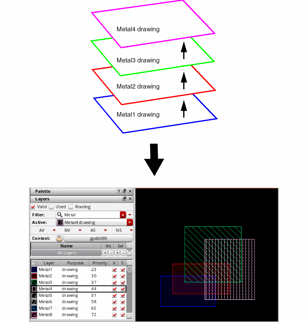
techLayerPurposePriorities(
 ; ( layerName     purposeName )
   ( Metal1        drawing     )
   ( Metal2        drawing     )
   ( Metal3        drawing     )
   ( Metal4        drawing     )
) ;techLayerPurposePriorities
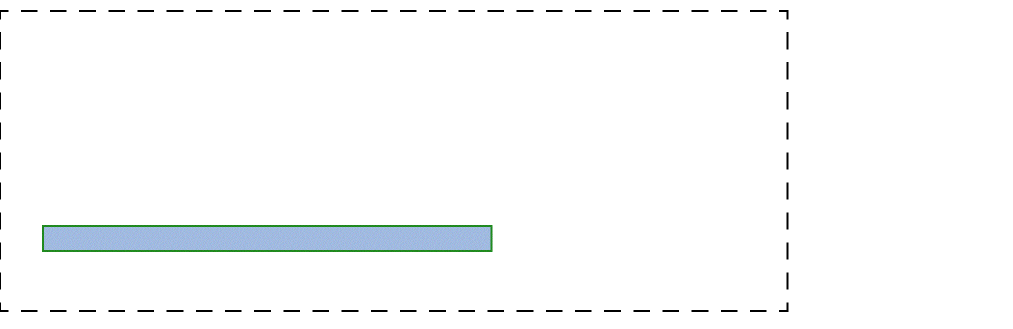
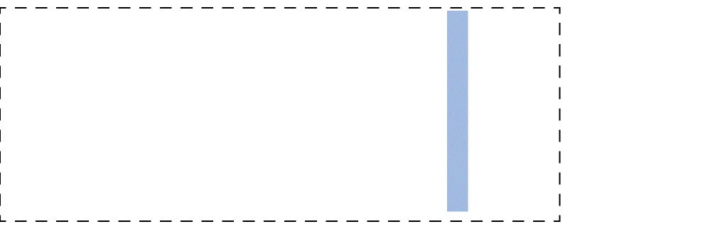
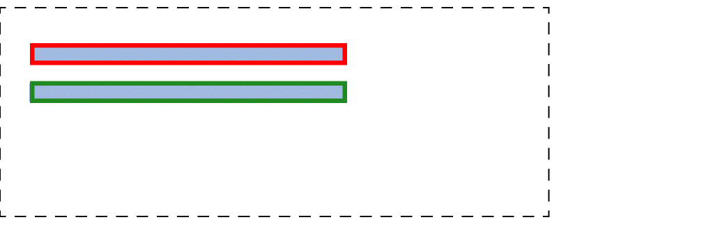
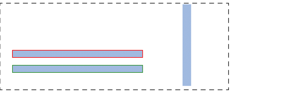
Defines layer-purpose pair priority based on the order in which the layer-purpose pairs are listed. For example, the layer-purpose pair listed first, Metal1 drawing, has the lowest priority, and the layer-purpose pair listed last, Metal4 drawing, has the highest priority. The priority assigned to the layer-purpose pairs determines how shapes are rendered in the layout. For example, shapes on the layer-purpose pair with the highest priority are drawn on top of the shapes on all other layer-purpose pairs.
The figure below illustrates how layer-purpose pairs are rendered based on the priority assigned to them. It also includes an example layout that shows shapes drawn on layers Metal1 through Metal4, with the Metal1 shape at the bottom and the Metal4 shape at the top.
techDisplays
techDisplays( (t_layerNamet_purposeNamet_packetg_visibleg_selectableg_contToChgLayg_dragEnableg_valid['allowSetToValid t/nil] ['descriptiont_description] ) … )
Description
Defines the display attributes of layer-purpose pairs.
Arguments
|
Name of a packet defined in the display resource file. For more information about display packets and the display resource file, see Chapter 11, “Display Resource File”. |
|
|
Indicates whether the layer is visible in the display device. |
|
|
Indicates whether the objects drawn on the layer are selectable. |
|
|
Indicates whether you can drag a shape created on the layer in the layout editor. |
|
|
Indicates whether the layer appears in the Palette Assistant window. |
|
|
The default value of this Boolean attribute is |
|
|
This string can be used to specify a brief description of the display attributes. |
|
Example
techDisplays(
 ; ( layer   Purpose   Packet      Vis   Sel   chgLay   drag   valid
 ;   attribute)
   ( poly1   boundary  redHash_S   t     t     t        t      t
     'allowSetToValid nil 'description "poly boundary layer")
)
Sets the display packet to redHash_s for poly1 boundary layer-purpose pair (LPP). In addition, the visible, selectable, change layer, drag enable, and valid attributes are all set to t. The 'allowSetToValid attribute is set to nil.
techLayerProperties
techLayerProperties( (t_propNamet_layer1[t_layer2]g_propValue) …
) ;techLayerProperties
Description
Stores properties for specific user-defined layers. Must be contained within the layerDefinitions enclosure.
The following are the properties that can be specified:
Arguments
Example
techLayerProperties(
    ( sheetResistance        METAL1                      0.02 )
    ( areaCapacitance        (METAL1 drawing)            4.1e-4 )
    ( areaCapacitance        METAL1        METAL2        2.36-5 )
    ( edgeCapacitance        METAL1                      3.0e-5 )
    ( edgeCapacitance        METAL1        METAL2        5.0e-6 )
) ;techLayerProperties
techDerivedLayers
With techDerivedLayers, you can specify:
- Purpose-Aware–Derived Layers
- Sizing-Derived Layers
- Area-Restricted Derived Layers
- Color-Derived Layers
- Two-Layer–Derived Layers
- Non-rectangular Shape Derived Layers
Purpose-Aware–Derived Layers
techDerivedLayers( (tx_derivedLayerx_derivedLayerNum(tx_layer'selecttx_purpose) ) …
) ;techDerivedLayers
Description
Defines layers derived by pairing a layer with a purpose. Purpose-aware derived layers allow selection of a layer with the specified purpose for purpose-aware constraint application.
Arguments
Example
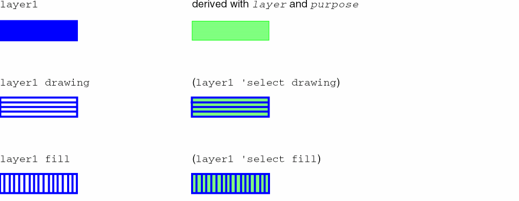
techDerivedLayers(
   ("derivedLayerPurpose1" 1000 ("metal1" 'select "drawing"))
   ("derivedLayerPurpose2" 1001 ("metal1" 'select "fill"))
)
Defines a derived layer named derivedLayerPurpose1 with layer number 1000, created by selecting layer metal1 and purpose drawing. It also defines a derived layer named derivedLayerPurpose2 with layer number 1001, created by selecting layer metal1 and purpose fill.
Sizing-Derived Layers
techDerivedLayers( (tx_derivedLayerx_derivedLayerNum(tx_layers_sizeOpg_value) ) …
) ;techDerivedLayers
Description
Defines layers derived from sizing other layers.
Arguments
Example
techDerivedLayers(
(metal1Sized  20001  ( "Metal1" 'grow  0.01))
)
Defines a derived layer named metal1sized with layer number 20001, with all shapes on Metal1 grown by 0.01um.
Area-Restricted Derived Layers
techDerivedLayers( (tx_derivedLayer(tx_layer'areax_area) ) …
) ;techDerivedLayers
Description
Defines derived layers with restricted area.
Arguments
Example
techDerivedLayers(
   ("derivedLayer1" 1000 ("metal1" 'area <5))
)
Defines a derived layer named derivedLayer1 with layer number 1000 by restricting the area to less than 5.
Color-Derived Layers
techDerivedLayers( (t_derivedLayerNamex_derivedLayerNum(tx_layerName'colort_maskColor) ['locked | 'unlocked] ) …
) ;techDerivedLayers
Description
(Virtuoso Advanced Node for Layout Only) Creates a derived layer and copies to it shapes based on their color mask and color locked state, if specified.
Arguments
Example
The metal1 layer has both locked and unlocked colored shapes and one gray shape, as shown below. The various scenarios explain how shapes can be copied to the derived layer.
Scenario 1
techDerivedLayers(
    ( metal1_RedLocked 131 ( metal1 'color  mask1Color ) 'locked )
)
Creates a derived layer named metal1_RedLocked with layer number 131 and copies to it the locked mask1Color shape, as shown below.
Scenario 2
techDerivedLayers(
    ( metal1_GreenUnlocked 131 ( metal1 'color  mask2Color ) 'unlocked )
)
Creates a derived layer named metal1_GreenUnlocked with layer number 131 and copies to it the unlocked mask2Color shape, as shown below.
Scenario 3
techDerivedLayers(
    ( metal1_Gray 131 ( metal1 'color grayColor ) 'unlocked )
)
Creates a derived layer named metal1_Gray with layer number 131 and copies to it the unlocked grayColor shape, as shown below.
Scenario 4
techDerivedLayers(
    ( metal1_Locked 131 ( metal1 'color  any ) 'locked )
)
Creates a derived layer named metal1_Locked with layer number 131 and copies to it all locked shapes, as shown below.
Scenario 5
techDerivedLayers(
    ( metal1_UnLocked 131 ( metal1 'color any ) 'unlocked )
)
Creates a derived layer named metal1_UnLocked with layer number 131and copies to it all unlocked shapes, as shown below.
Two-Layer–Derived Layers
techDerivedLayers( (t_derivedLayerNamex_derivedLayerNum(tx_layer1s_optx_layer2) [x_count|t_rangeVal] [ 'diffNet | 'sameNet ] [ 'exclusive ] ) …
) ;techDerivedLayers
Description
Defines derived layers to be used throughout the technology file. A derived layer is the result of performing a logical operation on two layers.
Arguments
|
The name to apply to the derived layer. |
|
|
The layer number for the derived layer. |
|
|
The first layer used to create the derived layer. |
|
|
The logical operation to perform on the two layers to create the derived layer. Only one logical operator can be used in the creation of a derived layer.
The other operators are explained in Operator Definitions. |
|
|
The second layer used to create the derived layer. |
|
|
The number of times contact must be made between the shapes on the two layers forming the derived layer. |
|
|
A range of the number of times contact can be made between the shapes on the two layers forming the derived layer.
Valid values:
where, n is the count, n1 is the lower number in a range, n2 is the upper number in a range, |
|
|
The shapes on layer1 and layer2 must be on different nets. If not specified, connectivity is ignored. |
|
|
The shapes on layer1 and layer2 must be on the same net. If not specified, connectivity is ignored. |
|
|
This specification must define the only derived layer relationship between shapes on layer1 and shapes on layer2. |
Operator Definitions
| Operator | Definition |
|---|---|
|
The 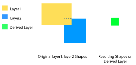 |
|
|
The 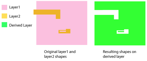 |
|
|
The 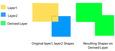 |
|
|
The 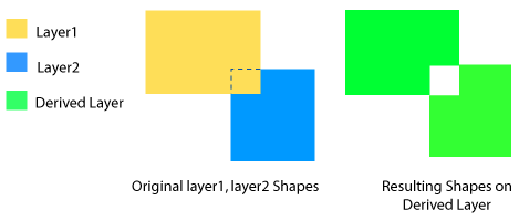 |
|
|
The 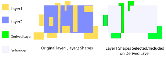 |
|
|
The 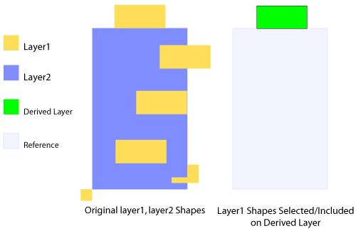 |
|
|
The 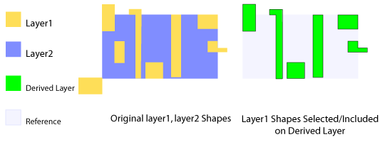 |
|
|
The 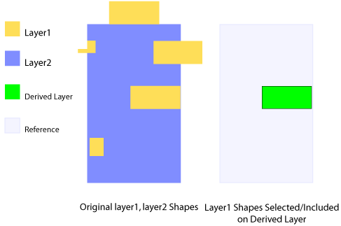 |
|
|
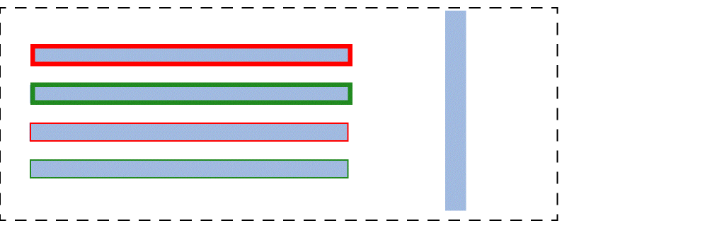
The For more information, see 'butting and 'coincident. 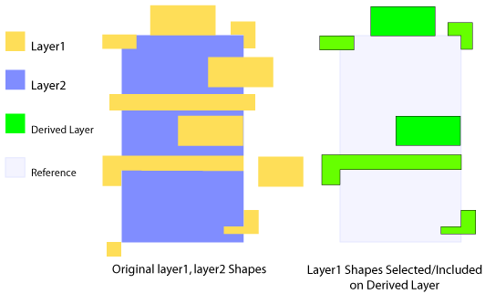 |
|
|
The 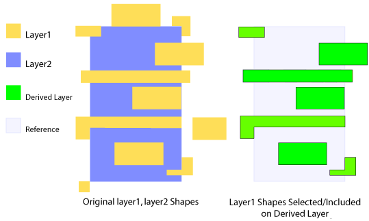 |
|
|
The For more information, see 'butting and 'overlapping.
The
'buttingOrOverlapping layer operation is the same as the 'touching layer operation, but the latter does not support optional parameters. 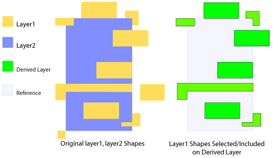 |
|
|
The
None of the optional parameters can be specified when a derived layer definition contains the
'touching operator. To specify any of these optional parameters, use 'buttingOrOvelapping.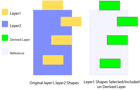 |
|
|
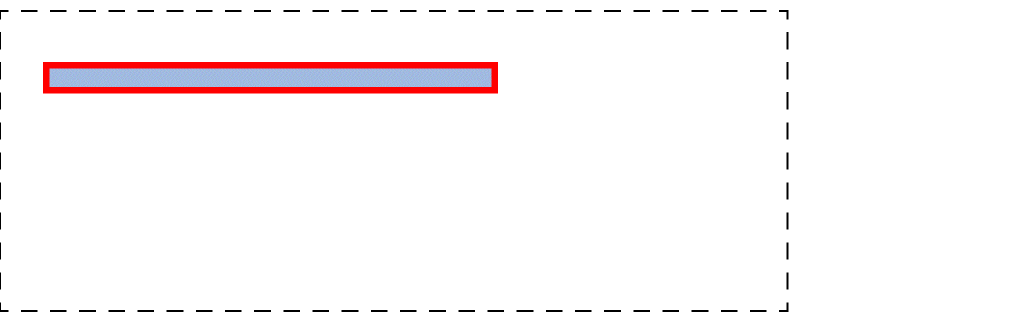
The The difference between this and the 'touching layer operation is that this operation does not include the abutting shapes that are outside the layer2 shapes and overlapping shapes that are only partially inside the layer2 shapes. The following figure is an example of shapes included in a derived layer when this type of layer operation is used. 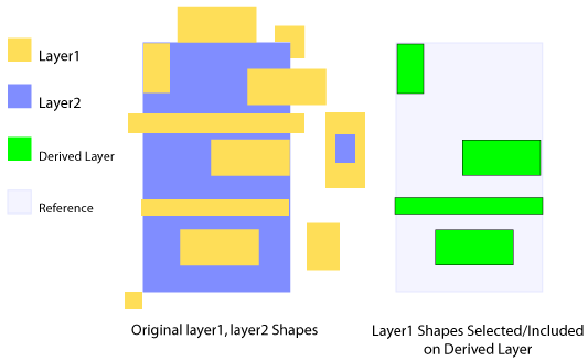 |
|
|
The 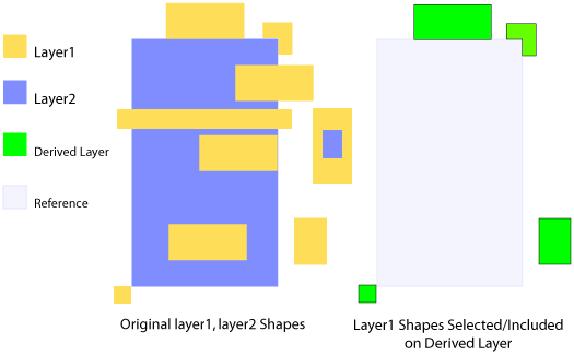 |
|
|
The 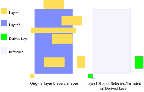 |
|
|
The 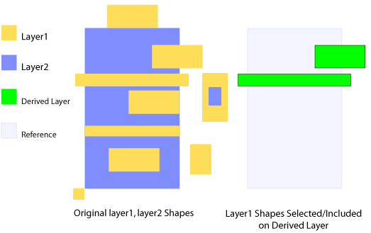 |
|
|
The 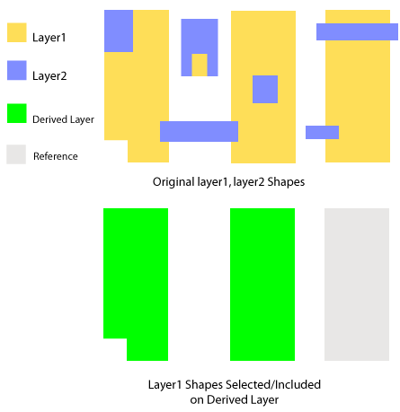 |
|
Non-rectangular Shape Derived Layers
techDerivedLayers( (tx_derivedLayerx_derivedLayerNum(tx_layer'notRect ) )
Description
Defines derived layers with non-rectangular shapes.
Arguments
Example
techDerivedLayers(
    ( notRect1 25020 ( metal1 'notRect))
)
Defines a derived layer named notRect1, with all non-rectangular shapes on layer metal1.
LPP Validity
A layer-purpose pair (LPP) is created from a combination of a single layer and a single purpose object defined in the technology database.
There are several ways of controlling the validity of an LPP. The valid attribute of the LPId can be set directly to true or false. However, the effective validity of the LPP depends on the valid attribute set for the parent layer, the parent purpose, and the LPP itself. Therefore, the effective LPP validity is equal to layer valid && purpose valid && lp base valid.
The layer valid attribute contributes to the validity of all layer-purpose pairs that the layer is part of. Similarly, the purpose valid attribute contributes to the validity of all layer-purpose pairs that the purpose is part of. The default values of layer and purpose valid attributes are true.
The ability to set the valid attributes of a layer, purpose, or layer-purpose pair can be controlled by the following attributes:
-
allowSetToValid: This attribute is persistent. -
allowSetToValidInSession: This attribute is not persistent and applies only during the current session.
These attributes exist on the layer, purpose, and layer-purpose pair objects.
If an object’s allowSetToValid or allowSetToValidInSession attribute is false, the valid attribute may not be set to true.
The allowSetToValid and allowSetToValidInSession attributes can always be set to false. However, the attributes can only be set to true when the parent technology database is opened in the "write" or "append" mode.
LPP Validity Attributes
-
layerId~>valid
Gets or sets the layervalidattribute. The attribute can be changed totrueonly when the layer attributesallowSetToValidandallowSetToValidInSessionaretrue. The default value istrue. -
layerId~>allowSetToValid
Gets or sets the layerallowSetToValidattribute. The attribute can be changed totrueonly when the technology database of the corresponding layer is opened in "append" or "write" mode. This attribute is persistent and the default value istrue. -
layerId~>allowSetToValidInSession
Gets or sets the layerallowSetToValidInSessionattribute. The attribute can be changed totrueonly when the technology database of the corresponding layer is opened in "append" or "write" mode. This attribute is not persistent and the default value istrue. -
purposeDefId~>valid
Gets or sets the purposevalidattribute. The attribute can be changed totrueonly when the purpose attributesallowsetToValidandallowSetToValidInSessionaretrue. The default value istrue. -
purposeDefId~>allowSetToValid
Gets or sets the purposeallowSetToValidattribute. The attribute can be changed totrueonly when the technology database of the corresponding purpose is opened in "append" or "write" mode. This attribute is persistent and the default value istrue. -
purposeDefId~>allowSetToValidInSession
Gets or sets the purposeallowSetToValidInSessionattribute. The attribute can be changed totrueonly when the technology database of the corresponding purpose is opened in "append" or "write" mode. This attribute is not persistent and the default value istrue. -
lpId~>allowSetToValid
Gets or sets the LPPallowSetToValidattribute. The attribute can be changed totrueonly when the technology database of the corresponding LPP is opened in "append" or "write" mode. This attribute is persistent and the default value istrue. -
lpId~>allowSetToValidInSession
Gets or sets the LPPallowSetToValidInSessionattribute. The attribute can be changed totrueonly when the technology database of the corresponding LPP is opened in "append" or "write" mode. This attribute is not persistent and the default value istrue. -
techIsLPValidBase(lpId)
Checks if the LPP basevalidattribute istrue. -
lpId~>valid
Gets the effective LPPvalidattribute. Effective LPPvalidattribute is equal to layervalid&& purposevalid&& LPP basevalid.
Sets the LPP basevalidattribute. The LPP basevalidattribute can be changed totrueonly when the following conditions are met:
Return to top