6
Automatically Creating Cellviews
This chapter discusses the following topics:
- Features of Creating Cellviews
- Automatically Creating a Cellview from Another Cellview
- Automatically Creating a Cellview from a Pin List
- Automatically Creating a Cellview from an Instance
- Creating a Cellview from the Canvas (Make Cell)
- Editing Symbol Generation Options
-
Specifying Symbol Generator Pin SortingFor more information on cellview creation, see also VHDL In Forms in the VHDL In for Virtuoso Design Environment User Guide and Reference.
Features of Creating Cellviews
- Create a new cellview from an existing cellview. See Automatically Creating a Cellview from Another Cellview.
- Create a new cellview from a list of port/pin names. See Automatically Creating a Cellview from a Pin List.
- Create a new cellview from an existing instance. See Automatically Creating a Cellview from an Instance.
- Create a new cellview from the canvas by using Make Cell. See Creating a Cellview from the Canvas (Make Cell).
-
Generate circuit symbols for schematic capture and subsequent simulation processes
You can automatically generate a symbol from a list of pins in a text-to-symbol generator (TSG) file. Refer to the in Text-to-Symbol Generator. - Generate symbol and simulation views. Refer to the Cadence® SKILL-based library management program in Symbol and Simulation Library Generator.
The software uses the TSG program to generate a symbol when you choose either Create – Cellview – From Cellview or Create – Cellview – From Pin List.
Automatically Creating a Cellview from Another Cellview
You can automatically create a new
To create a cellview from another cellview,
-
From the view, choose Create – Cellview – From Cellview.
The Cellview From Cellview form appears.
By default, the software initializes the form with information about the cellview currently open (the default cellview).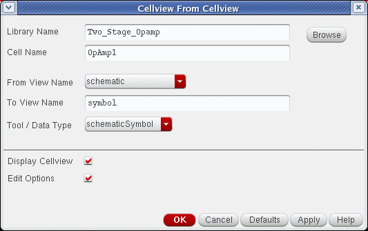
- Use a different cellview as the source of the port/pin information by changing the Library Name, Cell Name, and From View Name fields.
-
Change the To View Name or Tool / Data Type field to change the cellview to be created.If either the From View Name cyclic field or the Tool / Data Type cyclic field does not contain the desired view or conversion function, you must modify the
schViewToPinListReglist or theschPinListToViewReglist, which are defined in yourschConfig.ilfile, which is described in Virtuoso Design Environment User Guide. - Display the cellview in a new window by turning on the Display Cellview button.
- Edit various cellview creation options by turning on the Edit Options button.
-
Click OK.
When generating a symbol, the Symbol Generation Options form appears if you turned on the Edit Options button and the cellview is being newly created or replaced.
If a cellview already exists with the same name, a dialog box prompts you to either replace the cellview, modify it (symbol cellview only), or cancel the command.
From this point, the exact behavior of the command depends on the type of data being created.
sigType property (by default “signal”) and pins, then each symbol pin will inherit a sigType property that has the same value of the corresponding net.Replacing an Existing Symbol Cellview
You can replace or modify existing symbol cellviews. You can only replace (not modify) all other types of existing cellviews.
-
From the schematic window, choose Create – Cellview – From Cellview.
The Cellview From Cellview form appears.
-
In the To View Name field, type
symbol. -
Click OK.
If the symbol cellview to be created already exists, the Create Cellview dialog box appears. -
Click Replace.
The Symbol Generation Options form appears.
-
Click OK.
The Overwrite Base Cell CDF dialog box appears.
The existing cellview is deleted and a new one is created. - Click Yes.
Modifying an Existing Symbol Cellview
You can replace or modify existing symbol cellviews. You can only replace (not modify) all other types of existing cellviews.
-
From the view, do one of the following:
-
Choose Create – Cellview – From Cellview.
The Cellview From Cellview form appears.
-
Choose Create – Cellview – From Pin List.
The Cellview From Pin List form appears.
-
Choose Create – Cellview – From Cellview.
-
Click OK.
If the symbol cellview to be created already exists, the Create Cellview dialog box appears.
Note: Before clicking Modify, be aware that modifying a symbol cellview will:- automatically edit the cellview with a minimal amount of changes to the current pin locations, graphics, and properties within the symbol cellview.
- delete pins that are no longer needed.
- add pins that do not yet exist in the new cellview.
- add pins near the bottom of the cellview. Use the symbol editor to reposition these new pins and to adjust any symbol graphics. The system determines attributes of the new pins by the currently active TSG template file (see Loading and Saving a TSG Template File).
- add or update cellview properties and terminal properties.
- annotate the changes that were made in note format at the bottom of the cellview and in the Command Interpreter Window (CIW).
- not delete cellview or terminal properties.
-
Click Modify.
The symbol cellview is automatically edited and saved.
The Overwrite Base Cell CDF dialog box appears. - Click Yes to update the base cell CDF with new simInfo port information (see Figure 6-3).
Examples of Replacing and Modifying Pins on a Symbol
The following three figures show the difference between choosing Replace and Modify.
- Figure 6-1—The symbol
- Figure 6-2—The symbol after choosing Replace
- Figure 6-3—The symbol after choosing Modify
Figure 6-1 illustrates an original symbol that was created using Create – Cellview – From Cellview from a schematic that had the pins { a bb ccc dddd eeeee f gg hhh iii k ll mmm }.
The following changes were then made to the schematic:
-
Deleted input pin
bb -
Deleted inputOutput pin
iii -
Added input pins
wwwwwwandzz -
Added inputOutput pin
ii
All three figures show pin a at the exact same location, (X,Y) = (0,0) which is the origin point of the symbol. By default, TSG puts the top-most left pin at the origin of the symbol.
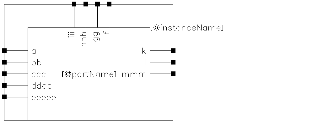
Figure 6-2 The Symbol after Choosing Replace
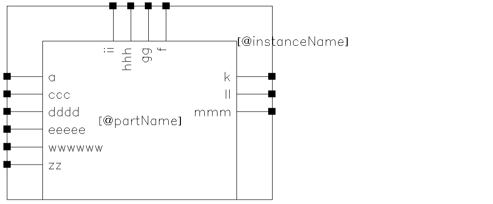
After a Replace, only pin a is in the exact same position as the original pins. All other unaffected pins are in new locations for the following reasons:
-
Pins
ccc,dddd, andeeeeehave moved up by one grid space, which was freed up by the deletion of pinbb. -
Although the ordering and number of pins along the top is similar to the original (with new pin
iireplacing piniii), all four top pins have moved down by one-half a grid (due to the shorter label). -
Due to the length of new or deleted pin names, the graphic has been recalculated in size accordingly.
Figure 6-3 The Symbol after Choosing Modify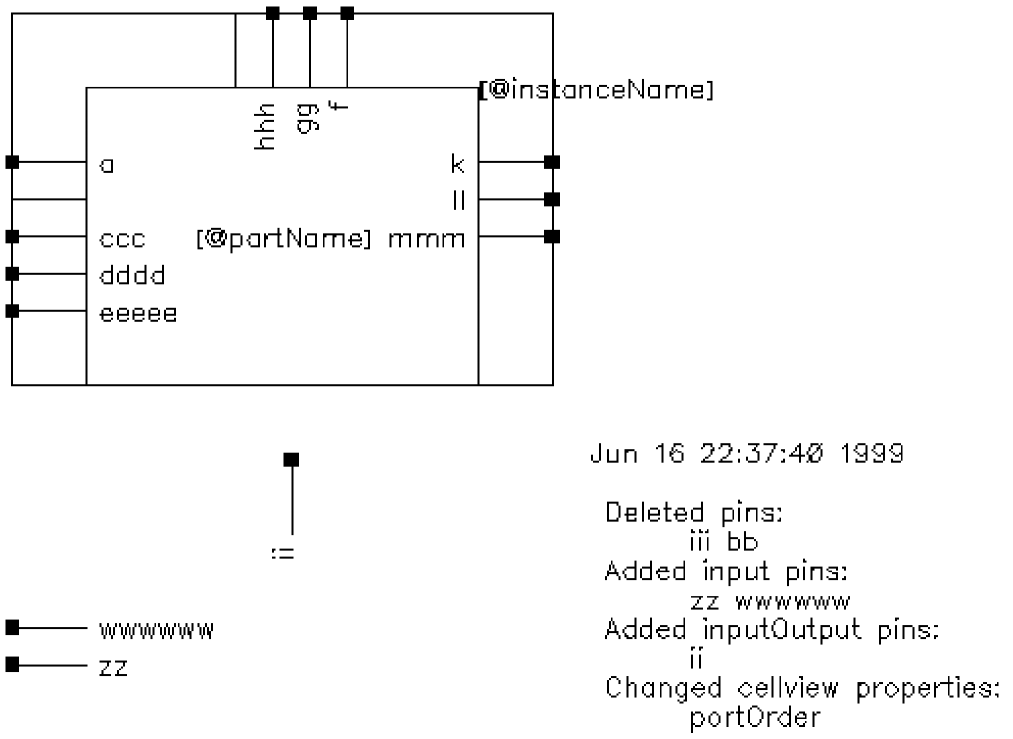
The modified cellview has all of the unaffected pins {a ccc dddd eeeee f gg hhh k ll mmm} at their original locations. The new pins {wwwwww, zz, ii} have been placed at the bottom of the cellview, outside of the bounding box of the original symbol. The pin and pin names {bb, iii} have been deleted, but the graphic pin line (pin stub) remains to show the position of the pins that were deleted. If necessary, you can delete these graphic pin lines using the symbol editor. Also shown is the note used to describe the changes that were made to the symbol.
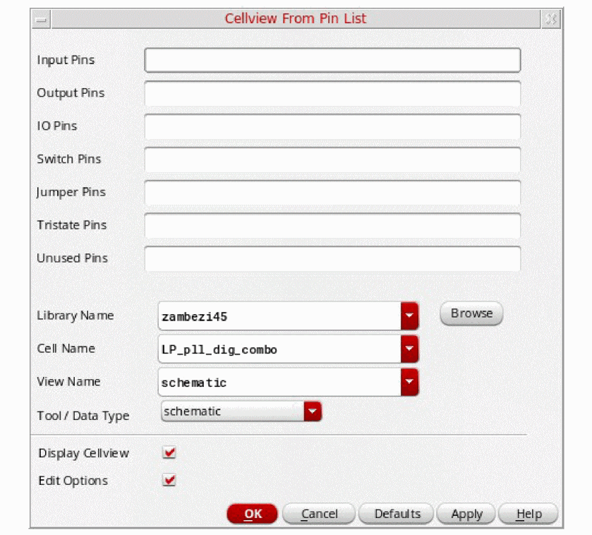
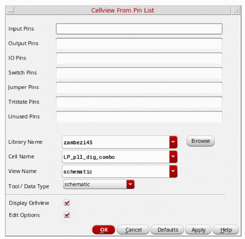
Automatically Creating a Cellview from a Pin List
A pin list can be any list of input, output, I/O, or switch pins. You can create a cellview from existing pins, such as those from the basic pin library, or you can create the cellview from new pin names.
To create a symbol cellview from a pin list,
-
From the view, choose Create – Cellview – From Pin List.
The Cellview From Pin List form appears.
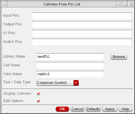
- Type the names of the pins that you want to appear in the automatically created cellview. Separate each pin name with a space.
-
(Optional) To use a different cellview as the source of the port/pin information, change the Library Name, Cell Name, and View Name fields.If either the View Name field or the Tool / Data Type cyclic field does not contain the desired view or conversion function, you must modify the
schViewToPinListReglist or theschPinListToViewReglist, both of which are defined in yourschConfig.ilfile, which is described in Virtuoso Design Environment User Guide. - (Optional) To display the cellview in a new window, turn on the Display Cellview button.
- (Optional) To edit various cellview creation options, turn on Edit Options.
-
Click OK.
When generating a symbol, the Symbol Generation Options form appears if you turned on Edit Options and the cellview is being newly created or replaced.
If the cellview already exists, a dialog box prompts you to either replace the cellview, modify it (symbol cellview only), or cancel the command.
The system generates the specified cellview from the pin information you enter on the form.
Automatically Creating a Cellview from an Instance
To create a cellview from an instance,
- From the view, choose Create – Cellview – From Instance.
-
Click an instance in your design window.
The Cellview From Instance form appears.
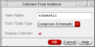
- Change the options on the form, if needed.
-
Click OK.
The system generates the specified cellview from the instance you selected. When you turn on Display Cellview, the system displays the cellview in a new window.
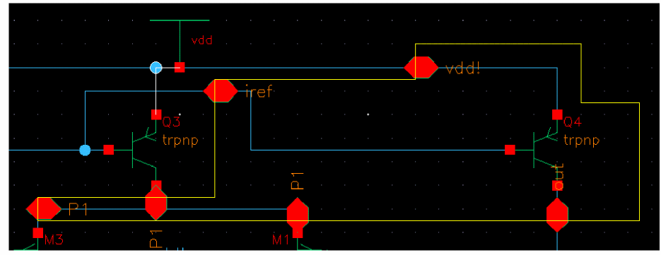
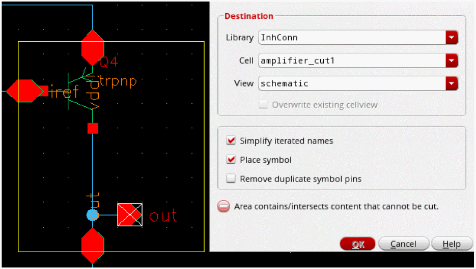
Creating a Cellview from the Canvas (Make Cell)
You can create a new cellview from objects within a specified canvas area by selecting that area, and using the Make Cell command. This process excludes the selection of pins.
To create a cellview from the current window:
- In Virtuoso Schematic Editor XL, choose Edit – Hierarchy – Make Cell.
-
Draw a rectangle on the canvas over the objects to be included. The cursor turns into an
 icon if an invalid object is selected.
The Make Cell form appears.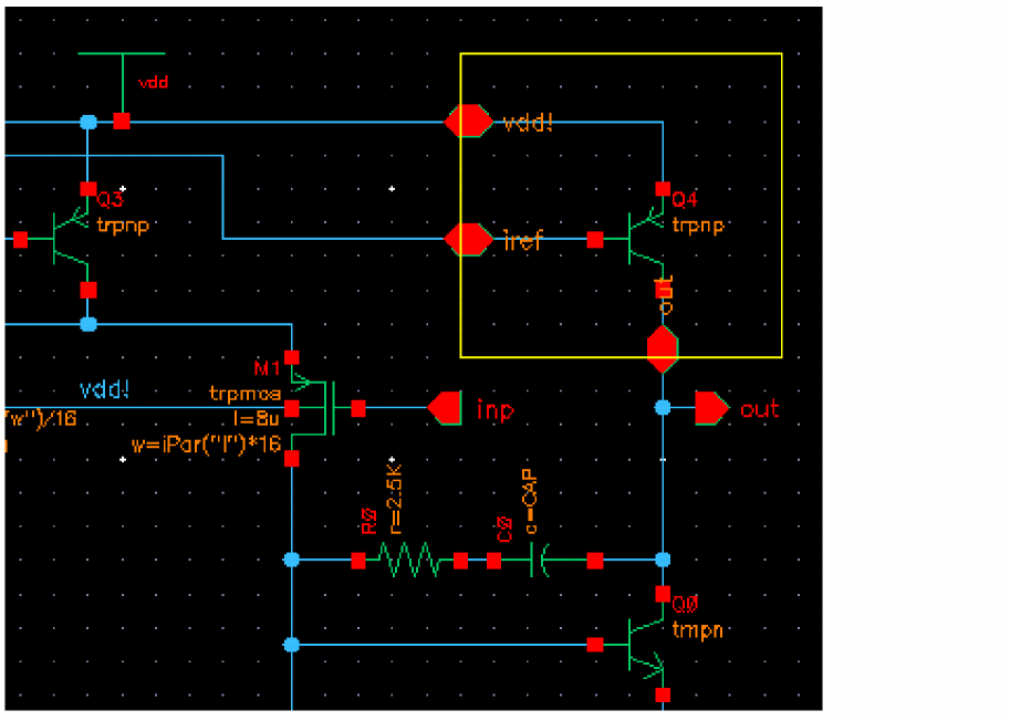
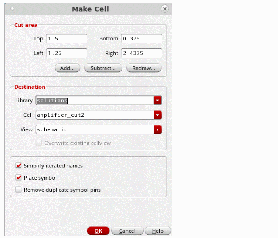
-
(Optional) Adjust the selection by using the options in the Cut area field.
- (Optional) Edit the destination by changing the Library, Cell, and View fields.
- Select or deselect the Simplify iterated names check box.
-
Select or deselect the Place symbol check box. Deselecting it places the new cell directly in the current schematic:
-
Select or deselect the Remove duplicate symbol pins check box. This is only available when Place symbol is selected.If any incorrect selections are made, the form displays an error message and the OK button is unavailable. Resolve any issues, for example, remove any pins from the selection. When all issues are resolved, the OK button becomes available.
-
Click OK.
The newly created cell is placed on the canvas.
- Click and drag the mouse to move the symbol cell the canvas.
-
(Optional) Press the
5key on the keyboard or select Edit – Route Flight to route the connections.
Editing Symbol Generation Options
The Symbol Generation Options form displays the property and attribute settings that the text-to-symbol generator (TSG) uses to generate symbols. The software loads the default form settings from a template file, which you specify using the tsgTemplateType environment variable.
This section discusses the following tasks:
- Adding, Changing, and Reordering Pin Names
- Editing Pin Attributes
- Excluding or Including Inherited Connection Pins
- Loading and Saving a TSG Template File
- Editing Symbol Attributes
- Editing Symbol Labels
- Creating a New Label
- Deleting Labels
- Modifying Label Attributes
- Editing Properties
- Creating a New Property
- Deleting Properties
- Modifying Property Attributes
Adding, Changing, and Reordering Pin Names
To add, change, or reorder pin names,
-
From the view, do one of the following:
-
Choose Create – Cellview – From Cellview.
The Cellview From Cellview form appears.
-
Choose Create – Cellview – From Pin List.
The Cellview From Pin List form appears.
-
Choose Create – Cellview – From Cellview.
- Turn on Edit Options.
-
Click OK.
If the symbol cellview to be created already exists, the Create Cellview dialog box appears.-
Click Replace.
The Symbol Generation Options form appears.
By default, the software initializes the form with information from the current cellview and the Cellview From Cellview.
-
Click Replace.
- To space pins further apart, add one or more asterisks ( * ) between the pin names in the Left Pins, Right Pins, Top Pins, and Bottom Pins fields.
-
Click OK.
This setting results in the following:
Editing Pin Attributes
To edit the attributes of a pin,
- From the view, do one of the following:
- Turn on Edit Options.
-
Click OK.
If the symbol cellview to be created already exists, the Create Cellview dialog box appears. -
Select List from one of the Attributes cyclic fields.
The Left, Right, Top, Bottom Pin Attributes form appears.
The banner title on the form indicates left, right, top, or bottom pin attributes.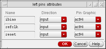
- Use the Direction cyclic fields to change the direction of the pins.
- Use the Pin Graphic cyclic fields to change the graphic of the pin.
- Click OK.
Excluding or Including Inherited Connection Pins
To exclude or include inherited connection pins in a symbol view:
-
Choose Create – Cellview – From Cellview.
The Cellview From Cellview form appears.
By default, the software initializes the form with information from the current cellview (in the Library Name, Cell Name, and View Name fields) and the Cellview From Cellview form.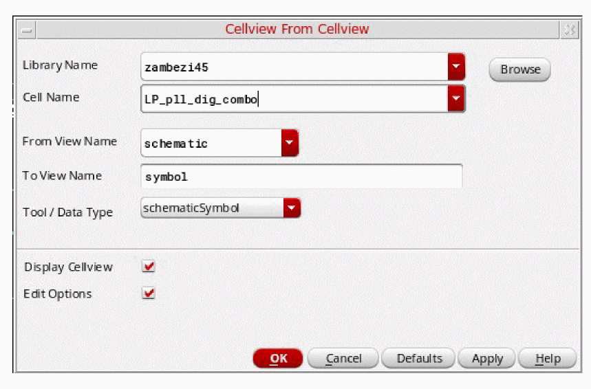
- In the To View Name field enter name of the symbol view to be created.
-
Click the OK button.
The Symbol Generation Options form is displayed.
-
Choose whether or not to Exclude Inherited Connection Pins, or name specific inherited connection pins to be excluded.
Some design flows will require pins with inherited connections to be explicitly shown on the symbol view, whereas other flows will require pins with inherited connection attributes to not be shown. To facilitate both cases the Exclude Inherited Connection Pins section allows you to specify whether all pins with inherited connections are to be excluded during symbol generation, or only a named set. The (Exclude) Only these option will be pre-seeded with the list of all the pins that show inherited connection attributes, and you can manually edit this list.
See also the tsgExcludeInhConnPins and tsgExcludeInhConnPinsNames environment variables. - Click OK to generate the new symbol view.
Editing Pin Label Defaults
You can use the Labels tab in the Editor Options form to control and override pin label properties such as font and justification settings.
- Select Options – Editor to display the Editor Options.
-
Click the Labels tab.
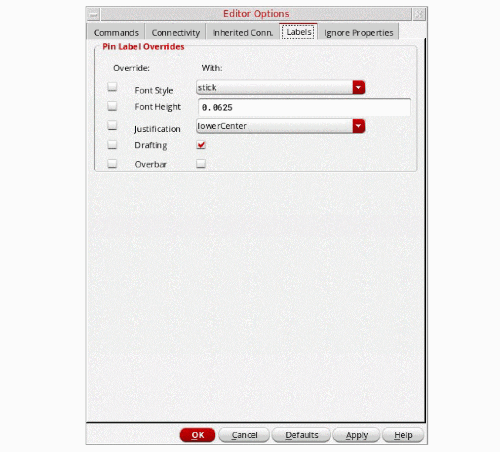
-
Amend the options in the Pin Label Overrides section as required.You have to first of all check the appropriate Override option, then you need to choose what you want to override this option With. For example, to apply an overbar, you will need to check both the checkboxes associated with this option, one to choose to override the Overbar option, and the other to apply the overbar.For more information see the Labels tab in the Editor Options form.
Click the OK button to apply the pin label overrides.
The above pin label options store their values in schematic environment variables, with two variables applicable for each option. One variable controls whether or not to override the associated symbol value, while the other provides the overriding value.
- pinLabelSetFontStyle
- pinLabelFontStyle
- pinLabelSetFontHeight
- pinLabelFontHeight
- pinLabelSetJustify
- pinLabelJustify
- pinLabelSetDrafting
- pinLabelSetDrafting
- pinLabelDrafting
- pinLabelSetOverbar
- pinLabelOverbar
Loading and Saving a TSG Template File
The TSG template file contains the default property and attribute settings that appear on the Symbol Generation Options form. The software loads the TSG template file the first time you use one of the Create Cellview commands to automatically generate a symbol. You use the tsgTemplateType environment variable to specify the TSG template file.
To load or save a TSG template file,
- From the view, do one of the following:
- Turn on Edit Options.
-
Click OK.
If the symbol cellview to be created already exists, the Create Cellview dialog box appears. -
In the Symbol Generation Options form, turn on Load / Save.
The Symbol Generation Options expands to display the template data fields.
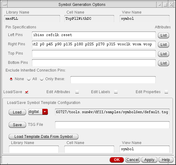
- In the Load / Save Symbol Template Configuration section, type the path to the TSG template file.
-
Click Load or Save.
The system initializes the Load / Save Symbol Template Configuration section of the form with the values from the specified TSG file.
The software builds all subsequent symbols using the new values.
Editing Symbol Attributes
-
From the view, do one of the following:
-
Choose Create – Cellview – From Cellview.
The Cellview From Cellview form appears. -
Choose Create – Cellview – From Pin List.
The Cellview From Pin List form appears.
-
Choose Create – Cellview – From Cellview.
- Turn on Edit Options.
-
Click OK.
If the symbol cellview to be created already exists, the Create Cellview dialog box appears.-
Click Replace.
The Symbol Generation Options form appears.
By default, the software initializes the form with information from the current cellview and the Cellview From Cellview form.
-
Click Replace.
-
In the Symbol Generation Options form, turn on Edit Attributes.
The Symbol Generation Options form expands to display the symbol attributes options.
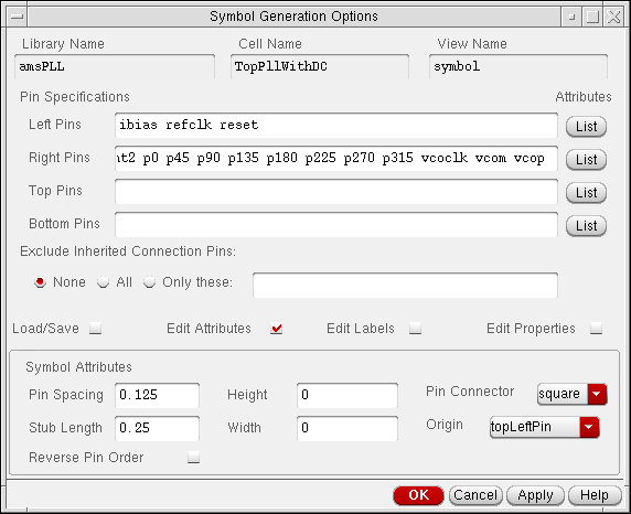
-
Edit the attributes.The symbol origin can be specified as
topLeftPin,bottomLeftPin, orcenterLeftin the Symbol Generation Options form or using the text-to-symbol generator (TSG) origin setting.-
If the symbol origin is
topLeftPin, the top-most, left-most pin is used. -
If the symbol origin is
bottomLeftPin, the bottom-most, left-most pin is used. -
If the symbol origin is
centerLeft, the origin is the middle of the left-hand side of the symbol box.
-
If the symbol origin is
- Click OK.
Editing Symbol Labels
- From the view, do one of the following:
- Turn on Edit Options.
-
Click OK.
If the symbol cellview to be created already exists, the Create Cellview dialog box appears.-
Click Replace.
The Symbol Generation Options form appears.
By default, the software initializes the form with information from the current cellview and the Cellview From Cellview form.
-
Click Replace.
-
In the Symbol Generation Options form, turn on Edit Labels.
The Symbol Generation Options form expands to display the label options.
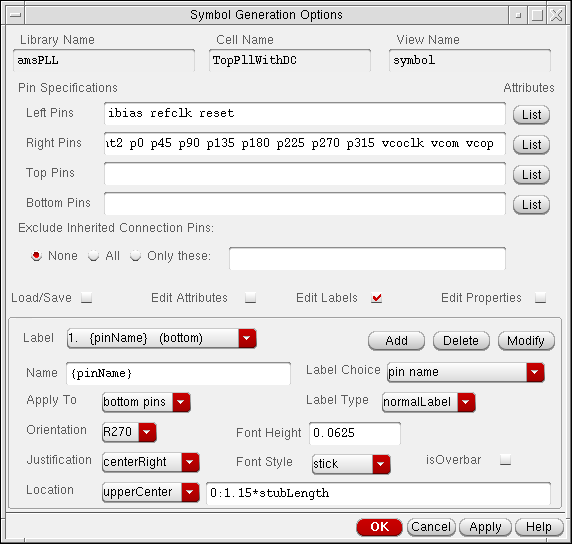
- Edit the symbol labels.
- Click OK.
Creating a New Label
-
From the view, do one of the following:
-
Choose Create – Cellview – From Cellview.
The Cellview From Cellview form appears. -
Choose Create – Cellview – From Pin List.
The Cellview From Pin List form appears.
-
Choose Create – Cellview – From Cellview.
- Turn on Edit Options.
-
Click OK.
If the symbol cellview to be created already exists, the Create Cellview dialog box appears.-
Click Replace.
The Symbol Generation Options form appears.
By default, the software initializes the form with information from the current cellview and the Cellview From Cellview form.
-
Click Replace.
-
In the Symbol Generation Options form, turn on Edit Labels.
The Symbol Generation Options form expands to display the data that can be edited.
- In the Label cyclic field, choose new.
- Choose the desired Label Choice and other options.
- In the Name field, type the name of the new label.
- In the Apply To field, specify which objects the label attaches to.
-
Click Add.
The new label name is added to the list of labels that will automatically be created during symbol generation.
Deleting Labels
To delete a symbol label from the Label cyclic field,
-
From the view, do one of the following:
-
Choose Create – Cellview – From Cellview.
The Cellview From Cellview form appears. -
Choose Create – Cellview – From Pin List.
The Cellview From Pin List form appears.
-
Choose Create – Cellview – From Cellview.
- Turn on Edit Options.
-
Click OK.
If the symbol cellview to be created already exists, the Create Cellview dialog box appears.-
Click Replace.
The Symbol Generation Options form appears.
By default, the software initializes the form with information from the current cellview and the Cellview From Cellview form.
-
Click Replace.
-
In the Symbol Generation Options form, turn on Edit Labels.
The Symbol Generation Options form expands to display the label options. - In the Label cyclic field, choose the name of the label you want to delete.
-
Click Delete.
The label name no longer appears in the Label cyclic field.
Modifying Label Attributes
-
From the view, do one of the following:
-
Choose Create – Cellview – From Cellview.
The Cellview From Cellview form appears. -
Choose Create – Cellview – From Pin List.
The Cellview From Pin List form appears.
-
Choose Create – Cellview – From Cellview.
- Turn on Edit Options.
-
Click OK.
If the symbol cellview to be created already exists, the Create Cellview dialog box appears.-
Click Replace.
The Symbol Generation Options form appears.
By default, the software initializes the form with information from the current cellview and the Cellview From Cellview form.
-
Click Replace.
-
In the Symbol Generation Options form, turn on Edit Labels.
The Symbol Generation Options form expands to display the label options. - In the Label cyclic field, choose the name of the label you want to modify.
- Make any desired changes to the various label display attributes or label location fields.
-
Click Modify.
The label is modified.
Editing Properties
-
From the view, do one of the following:
-
Choose Create – Cellview – From Cellview.
The Cellview From Cellview form appears. -
Choose Create – Cellview – From Pin List.
The Cellview From Pin List form appears.
-
Choose Create – Cellview – From Cellview.
- Turn on Edit Options.
-
Click OK.
If the symbol cellview to be created already exists, the Create Cellview dialog box appears.-
Click Replace.
The Symbol Generation Options form appears.
By default, the software initializes the form with information from the current cellview and the Cellview From Cellview form.
-
Click Replace.
-
In the Symbol Generation Options form, turn on Edit Properties.
The Symbol Generation Options form expands.
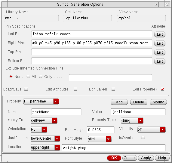
- Edit any property.
- Click OK.
Creating a New Property
-
From the view, do one of the following:
-
Choose Create – Cellview – From Cellview.
The Cellview From Cellview form appears. -
Choose Create – Cellview – From Pin List.
The Cellview From Pin List form appears.
-
Choose Create – Cellview – From Cellview.
- Turn on Edit Options.
-
Click OK.
If the symbol cellview to be created already exists, the Create Cellview dialog box appears.-
Click Replace.
The Symbol Generation Options form appears.
By default, the software initializes the form with information from the current cellview and the Cellview From Cellview form.
-
Click Replace.
-
In the Symbol Generation Options form, turn on Edit Properties.
The Symbol Generation Options form expands. - In the Property cyclic field, choose new.
- In the Name field, type the name of the new label.
- In the Apply To field, specify which objects the label attaches to.
-
Click Add.
The new property name is added to the list of properties that are automatically created during symbol generation.
Deleting Properties
-
From the view, do one of the following:
-
Choose Create – Cellview – From Cellview.
The Cellview From Cellview form appears. -
Choose Create – Cellview – From Pin List.
The Cellview From Pin List form appears.
-
Choose Create – Cellview – From Cellview.
- Turn on Edit Options.
-
Click OK.
If the symbol cellview to be created already exists, the Create Cellview dialog box appears.-
Click Replace.
The Symbol Generation Options form appears.
By default, the software initializes the form with information from the current cellview and the Cellview From Cellview form.
-
Click Replace.
-
In the Symbol Generation Options form, turn on Edit Properties.
The Symbol Generation Options form expands. - In the Properties cyclic field, choose the name of the property you want to delete.
-
Click Delete.
The property no longer appears in the Properties cyclic field.
Modifying Property Attributes
To modify property attributes,
-
From the view, do one of the following:
-
Choose Create – Cellview – From Cellview.
The Cellview From Cellview form appears. -
Choose Create – Cellview – From Pin List.
The Cellview From Pin List form appears.
-
Choose Create – Cellview – From Cellview.
- Turn on Edit Options.
-
Click OK.
If the symbol cellview to be created already exists, the Create Cellview dialog box appears.-
Click Replace.
The Symbol Generation Options form appears.
By default, the software initializes the form with information from the current cellview and the Cellview From Cellview form.
-
Click Replace.
-
In the Symbol Generation Options form, turn on Edit Properties.
The Symbol Generation Options form expands. - In the Properties cyclic field, choose the property name you want to modify.
- Make any desired changes to the various property display attributes or property location fields.
- Click Modify.
Specifying Symbol Generator Pin Sorting
When symbols are automatically created, TSG sorts the pins either alphanumerically by pin name (default) or geometrically according to the pin’s relative position in the source schematic view.
To specify how TSG sorts the pins,
-
From the view, choose Options – Editor.
The Editor Options form appears. - In the Command Controls section of the form, set the Symbol Generator Pin Sorting option to alphanumeric or geometric.
-
Click OK.
Automatic symbol generation now uses the specified pin sorting method.
You can change the default (alphanumeric to geometric) by editing the ssgSortPins environment variable. The system uses this variable when you choose Options – Save Defaults. It is also available as arguments to the schGetEnv and schSetEnv procedural interface SKILL functions.
Return to top