Process of Creating the CPF Content
Overview
The content of the CPF file can grow through the design process. The tools in the design process need different information. Therefore you can start the design with an incomplete CPF file.
At the design stage, low power verification checks the following aspects of a design using PSO methodology:
Power up and power down of the design
State retention and restoration
Enabling and disabling of isolation
To perform low power verification, you need the following minimum set of commands to specify the power structures when starting from RTL:
set_design end_design create_power_domain create_nominal_condition create_power_mode create_state_retention_rule create_isolation_rule At the logic implementation stage, logic synthesis adds the required level shifter logic, isolation logic, state retention logic, and power switch logic to the gate-level netlist, and test synthesis adds the required test logic.
To drive synthesis and test, you need at least the following commands in addition to the commands listed above:
define_library_set define_isolation_cell define_level_shifter_cell define_state_retention_cell update_nominal_condition update_power_mode At the physical implementation stage, ATPG, and signoff, you need at least the following commands in addition to all commands listed above:
Note: You can run gate-level simulation after both logic and physical implementation.
Even when the CPF file that you read in contains more CPF commands than the tool needs, the tool will just read the ones it needs and will ignore the other ones.
The content change can be handled in several ways:
You can start with a CPF file and add to this file as you go through the design process.
You can include additional commands in a separate file and source it in the original CPF file.
A CPF file contains both the power intent for the design and the technology information. When you use multiple CPF files, you can capture the technology information in a separate file. Library-related definitions are captured in the define_xxx commands.
The power intent for the design captures the different power domains, the different power modes and transitions, and the specifications for the power logic. The power intent of the design is captured in the create_xxx commands. Implementation tools need more detailed information which is captured in the update_xxx commands. This information can be captured in a separate file.
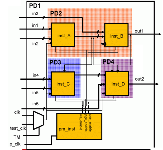
The example shown in Figure 3-1 is used to illustrate different approaches of CPF creation.
Figure 3-1 Example Design for CPF
Using a Single CPF File
#################################################
#       Technology part of the CPF
#################################################
# define the level shifters
define_level_shifter_cell -cells LVLHLEHX* \
   	 -input_voltage_range 1.2 \
   	 -output_power_pin VDD \
   	 -output_voltage_range 0.8 \
   	 -direction down \
   	 -output_voltage_input_pin EN \
   	 -ground VSS \
   	 -enable EN \
   	 -valid_location to
define_level_shifter_cell -cells LVLHLELX* \
   	 -input_voltage_range 1.2 \
   	 -output_power_pin VDD \
   	 -output_voltage_range 0.8 \
   	 -direction down \
   	 -output_voltage_input_pin EN \
   	 -ground VSS \
   	 -enable EN \
   	 -valid_location to
define_level_shifter_cell -cells LVLHLX* \
   	 -input_voltage_range 1.2 \
   	 -output_power_pin VDD \
   	 -output_voltage_range 0.8 \
   	 -direction down \
   	 -ground VSS \
   	 -valid_location to
define_level_shifter_cell -cells LVLLHEHX* \
   	 -input_voltage_range 0.8 \
   	 -output_power_pin VDD \
   	 -input_power_pin VDDI \
   	 -output_voltage_range 1.2 \
   	 -direction up \
   	 -output_voltage_input_pin EN \
   	 -ground VSS \
   	 -valid_location to
define_level_shifter_cell -cells LVLLHX* \
   	 -input_voltage_range 0.8 \
   	 -output_voltage_range 1.2 \
   	 -input_power_pin VDDI \
   	 -output_power_pin VDD \
   	 -direction up \
   	 -ground VSS \
   	 -valid_location to
# define the isolation cells
define_isolation_cell -cells ISOLN* \
   	 -enable EN \
   	 -power VDD -ground VSS \
   	 -valid_location to
# define the always on cell
define_always_on_cell -cells "BUFGX2M BUFGX8M INVGX2M INVGX8M" \
   	 -power_switchable VDD -power VDDG -ground VSS
# define the power switch cells
define_power_switch_cell -cells "HEAD8DM HEAD16DM HEAD32DM HEAD64DM" \
   	 -stage_1_enable !SLEEP \
   	 -type header \
   	 -stage_1_output SLEEPOUT \
   	 -power VDDG \
   	 -power_switchable VDD
define_power_switch_cell -cells "HEAD8M HEAD16M HEAD32M HEAD64M" \
   	 -stage_1_enable !SLEEP \
   	 -type header \
   	 -power VDDG \
   	 -power_switchable VDD
define_power_switch_cell -cells "FOOT8DM FOOT16DM" \
   	 -stage_1_enable SLEEPN \
   	 -type footer \
   	 -stage_1_output SLEEPNOUT \
   	 -ground VSSG \
   	 -ground_switchable VSS
define_power_switch_cell -cells "FOOT8M FOOT16M" \
   	 -stage_1_enable SLEEPN \
   	 -type footer \
   	 -ground VSSG \
   	 -ground_switchable VSS
# define the state retention cell
define_state_retention_cell -cells *DRFF* -restore_function RETN \
   	 -power VDDG \
   	 -power_switchable VDD \
   	 -ground VSS
# define the library sets
set vendor_08v_list "\
../LIBS/vendor_130/vendor13sp_tt_0p8v_25c.lib \
../LIBS/vendor_130LL/vendorl130e_ll_tt_0p8v_25c.lib \
../LIBS/vendor_130SP/vendorl130e_sp_tt_0p8v_25c.lib "
set vendor_120v_list "\
../LIBS/vendor_130/vendor13sp_tt_0p8v_1p2v_25c.lib \
../LIBS/vendor_130LL/vendorl130e_ll_tt_1p2v_25c.lib \
../LIBS/vendor_130SP/vendorl130e_sp_tt_1p2v_25c.lib "
define_library_set -name vendor_120v -libraries $vendor_120v_list
define_library_set -name vendor_08v -libraries $vendor_08v_list
#################################################
#       Design part of the CPF
#################################################
set_design top
set_hierarchy_separator "/"
# create power domains
create_power_domain -name PD1 -default
create_power_domain -name PD2 -instances {inst_A inst_B} \
   	 -shutoff_condition {pm_inst/pse_enable[0]}
create_power_domain -name PD3 -instances inst_C \
   	 -shutoff_condition {pm_inst/pse_enable[1]}
create_power_domain -name PD4 -instances inst_D \
   	 -shutoff_condition {pm_inst/pse_enable[2]}
create_power_domain -name LD1 -instances pm_inst/pd_inst*
# define the nominal conditions
create_nominal_condition -name point_8v -voltage 0.8
update_nominal_condition -name point_8v -library_set vendor_08v
create_nominal_condition -name one_p_2v -voltage 1.2
update_nominal_condition -name one_p_2v -library_set vendor_120v
create_nominal_condition -name off -voltage 0
# specify the power mode info
create_power_mode -name PM1 -default -domain_conditions {PD1@point_8v \
PD2@point_8v PD3@point_8v PD4@point_8v LD1@one_p_2v}
update_power_mode -name PM1 -sdc_files ../CPF/1.0/cm1.sdc
create_power_mode -name PM2 -domain_conditions {PD1@point_8v PD2@off \
PD3@point_8v PD4@point_8v LD1@one_p_2v}
create_power_mode -name PM3 -domain_conditions {PD1@point_8v PD2@off PD3@off \
PD4@point_8v LD1@one_p_2v}
create_power_mode -name PM4 -domain_conditions {PD1@point_8v PD2@off PD3@off \
PD4@off LD1@one_p_2v}
# create rules for state retention insertion
create_state_retention_rule -name st1 -domain PD2 \
-restore_edge {!pm_inst/pge_enable[0]}
create_state_retention_rule -name st2 -domain PD3 \
-restore_edge {!pm_inst/pge_enable[1]}
create_state_retention_rule -name st3 -domain PD4 \
-restore_edge {!pm_inst/pge_enable[2]}
# create rules for isolation logic insertion
create_isolation_rule -name iso1 -from PD2 \
-isolation_condition {pm_inst/ice_enable[0]}
create_isolation_rule -name iso2 -from PD3 \
-isolation_condition {pm_inst/ice_enable[1]}
create_isolation_rule -name iso3 -from PD4 \
-isolation_condition {pm_inst/ice_enable[2]}
# create rules for level shifter insertion
create_level_shifter_rule -name ls1 -to LD1
create_level_shifter_rule -name ls2 -from LD1
# declare power and ground nets
create_power_nets -nets VDD_0.8 -voltage 0.8
create_power_nets -nets VDD2 -voltage 0.8
create_power_nets -nets VDD3 -voltage 0.8
create_power_nets -nets VDD4 -voltage 0.8
create_power_nets -nets VDDH -voltage 1.2
create_ground_nets -nets VSS
# create global connections
create_global_connection -domain PD1 -net VDD_0.8 -pins VDD
create_global_connection -domain PD1 -net VDD_0.8 -pins VDDG
create_global_connection -domain PD1 -net VSS -pins VSS
create_global_connection -domain PD1 -net VSS -pins VSSG
create_global_connection -domain PD2 -net VDD2 -pins VDD
create_global_connection -domain PD2 -net VDD_0.8 -pins VDDG
create_global_connection -domain PD2 -net VSS -pins VSS
create_global_connection -domain PD2 -net VSS -pins VSSG
create_global_connection -domain PD3 -net VDD3 -pins VDD
create_global_connection -domain PD3 -net VDD_0.8 -pins VDDG
create_global_connection -domain PD3 -net VSS -pins VSS
create_global_connection -domain PD3 -net VSS -pins VSSG
create_global_connection -domain PD4 -net VDD4 -pins VDD
create_global_connection -domain PD4 -net VDD_0.8 -pins VDDG
create_global_connection -domain PD4 -net VSS -pins VSS
create_global_connection -domain PD4 -net VSS -pins VSSG
create_global_connection -domain LD1 -net VDDH -pins VDD
create_global_connection -domain LD1 -net VDD_0.8 -pins VDDI
create_global_connection -domain LD1 -net VSS -pins VSS
# add implementation info for power domains
update_power_domain -name LD1 -internal_power_net VDDH
update_power_domain -name PD1 -internal_power_net VDD_0.8
update_power_domain -name PD2 -internal_power_net VDD2
update_power_domain -name PD3 -internal_power_net VDD3
update_power_domain -name PD4 -internal_power_net VDD4
# update the rules
update_state_retention_rules -names st1 -cell_type DRFF -library_set vendor_08v
update_state_retention_rules -names st2 -cell_type DRFF -library_set vendor_08v
update_state_retention_rules -names st3 -cell_type DRFF -library_set vendor_08v
update_isolation_rules -names iso1 -location to -cells ISOLNX2M
update_isolation_rules -names iso2 -location to -cells ISOLNX2M
update_isolation_rules -names iso3 -location to -cells ISOLNX2M
update_level_shifter_rules -names ls1 -cells LVLLHX2M -location to -prefix RC_LS
# specify the power switch rule information
create_power_switch_rule -name SW1 -domain PD2 -external_power_net VDD_0.8
update_power_switch_rule -name SW1 -cells HEAD32M -prefix CDN_
create_power_switch_rule -name SW2 -domain PD3 -external_power_net VDD_0.8
update_power_switch_rule -name SW2 -cells HEAD32M -prefix CDN_
create_power_switch_rule -name SW3 -domain PD4 -external_power_net VDD_0.8
update_power_switch_rule -name SW3 -cells HEAD32M -prefix CDN_
end_design
Using Multiple CPF Files
In this case a master CPF file is created in which two other supporting CPF files with additional CPF commands are sourced.
pf_design_1.cpf(see Figure 3-2) contains the basic information used by most tools.library_vendor_130.cpf(see Figure 3-3) contains the technology-related information.pf_design_1_impl.cpf(see Figure 3-4) contains implementation-specific information.
Figure 3-2 Content of the pf_design_1.cpf File (Master CPF File)
#start of master CPF file
source library_vendor_130.cpf
set vendor_08v_list "\
../LIBS/vendor_130/vendor13sp_tt_0p8v_25c.lib \
../LIBS/vendor_130LL/vendorl130e_ll_tt_0p8v_25c.lib \
../LIBS/vendor_130SP/vendorl130e_sp_tt_0p8v_25c.lib "
set vendor_120v_list "\
../LIBS/vendor_130/vendor13sp_tt_0p8v_1p2v_25c.lib \
../LIBS/vendor_130LL/vendorl130e_ll_tt_1p2v_25c.lib \
../LIBS/vendor_130SP/vendorl130e_sp_tt_1p2v_25c.lib "
define_library_set -name vendor_120v -libraries $vendor_120v_list
define_library_set -name vendor_08v -libraries $vendor_08v_list
#################################################
#       Design part of the CPF
#################################################
set_design top
set_hierarchy_separator "/"
# create power domains
create_power_domain -name PD1 -default
create_power_domain -name PD2 -instances {inst_A inst_B} \
   	 -shutoff_condition {pm_inst/pse_enable[0]}
create_power_domain -name PD3 -instances inst_C \
   	 -shutoff_condition {pm_inst/pse_enable[1]}
create_power_domain -name PD4 -instances inst_D \
   	 -shutoff_condition {pm_inst/pse_enable[2]}
create_power_domain -name LD1 -instances pm_inst/pd_inst*
# create nominal conditions
create_nominal_condition -name point_8v -voltage 0.8
create_nominal_condition -name one_p_2v -voltage 1.2
create_nominal_condition -name off -voltage 0
# create power modes
create_power_mode -name PM1 -default -domain_conditions {PD1@point_8v \
PD2@point_8v PD3@point_8v PD4@point_8v LD1@one_p_2v}
create_power_mode -name PM2 -domain_conditions {PD1@point_8v PD2@off \
PD3@point_8v PD4@point_8v LD1@one_p_2v}
create_power_mode -name PM3 -domain_conditions {PD1@point_8v PD2@off \
PD3@off PD4@point_8v LD1@one_p_2v}
create_power_mode -name PM4 -domain_conditions {PD1@point_8v PD2@off \
PD3@off PD4@off LD1@one_p_2v}
# create rules for state retention insertion
create_state_retention_rule -name st1 -domain PD2 \
-restore_edge {!pm_inst/pge_enable[0]}
create_state_retention_rule -name st2 -domain PD3 \
-restore_edge {!pm_inst/pge_enable[1]}
create_state_retention_rule -name st3 -domain PD4 \
-restore_edge {!pm_inst/pge_enable[2]}
# create rule for isolation logic insertion
create_isolation_rule -name iso1 -from PD2 \
-isolation_condition {pm_inst/ice_enable[0]}
create_isolation_rule -name iso2 -from PD3 \
-isolation_condition {pm_inst/ice_enable[1]}
create_isolation_rule -name iso3 -from PD4 \
-isolation_condition {pm_inst/ice_enable[2]}
# create rules for level shifter insertion
create_level_shifter_rule -name ls1 -to LD1
create_level_shifter_rule -name ls2 -from LD1
source pf_design_1_impl.cpf
end_design
Figure 3-3 Content of the library_vendor_130.cpf File
#################################################
#       Technology part of the CPF
#################################################
# define the level shifters
define_level_shifter_cell -cells LVLHLEHX* \
   	 -input_voltage_range 1.2 \
   	 -output_power_pin VDD \
   	 -output_voltage_range 0.8 \
   	 -direction down \
   	 -output_voltage_input_pin EN \
   	 -ground VSS \
   	 -enable EN \
   	 -valid_location to
define_level_shifter_cell -cells LVLHLELX* \
   	 -input_voltage_range 1.2 \
   	 -output_power_pin VDD \
   	 -output_voltage_range 0.8 \
   	 -direction down \
   	 -output_voltage_input_pin EN \
   	 -ground VSS \
   	 -enable EN \
   	 -valid_location to
define_level_shifter_cell -cells LVLHLX* \
   	 -input_voltage_range 1.2 \
   	 -output_power_pin VDD \
   	 -output_voltage_range 0.8 \
   	 -direction down \
   	 -ground VSS \
   	 -valid_location to
define_level_shifter_cell -cells LVLLHEHX* \
   	 -input_voltage_range 0.8 \
   	 -output_power_pin VDD \
   	 -input_power_pin VDDI \
   	 -output_voltage_range 1.2 \
   	 -direction up \
   	 -output_voltage_input_pin EN \
   	 -ground VSS \
   	 -valid_location to
define_level_shifter_cell -cells LVLLHX* \
   	 -input_voltage_range 0.8 \
   	 -output_voltage_range 1.2 \
   	 -input_power_pin VDDI \
   	 -output_power_pin VDD \
   	 -direction up \
   	 -ground VSS \
   	 -valid_location to
# define the isolation cells
define_isolation_cell -cells ISOLN* \
   	 -enable EN \
   	 -power VDD -ground VSS \
   	 -valid_location to
# define the always on cell
define_always_on_cell -cells "BUFGX2M BUFGX8M INVGX2M INVGX8M" \
   	 -power_switchable VDD -power VDDG -ground VSS
# define the power switch cells
define_power_switch_cell -cells "HEAD8DM HEAD16DM HEAD32DM HEAD64DM" \
   	 -stage_1_enable !SLEEP \
   	 -type header \
   	 -stage_1_output SLEEPOUT \
   	 -power VDDG \
   	 -power_switchable VDD
define_power_switch_cell -cells "HEAD8M HEAD16M HEAD32M HEAD64M" \
   	 -stage_1_enable !SLEEP \
   	 -type header \
   	 -power VDDG \
   	 -power_switchable VDD
define_power_switch_cell -cells "FOOT8DM FOOT16DM" \
   	 -stage_1_enable SLEEPN \
   	 -type footer \
   	 -stage_1_output SLEEPNOUT \
   	 -ground VSSG \
   	 -ground_switchable VSS
define_power_switch_cell -cells "FOOT8M FOOT16M" \
   	 -stage_1_enable SLEEPN \
   	 -type footer \
   	 -ground VSSG \
   	 -ground_switchable VSS
# define the state retention cell
define_state_retention_cell -cells *DRFF* -restore_function RETN \
   	 -power VDDG \
   	 -power_switchable VDD \
   	 -ground VSS
Figure 3-4 Content of the pf_design_1_impl.cpf File
#start of implementation information
# associate library sets with nominal conditions
update_nominal_condition -name point_8v -library_set vendor_08v
update_nominal_condition -name one_p_2v -library_set vendor_120v
# specify timing constraints
update_power_mode -name PM1 -sdc_files ../CPF/1.0/cm1.sdc
# declare power and ground nets
create_power_nets -nets VDD_0.8 -voltage 0.8
create_power_nets -nets VDD2 -voltage 0.8
create_power_nets -nets VDD3 -voltage 0.8
create_power_nets -nets VDD4 -voltage 0.8
create_power_nets -nets VDDH -voltage 1.2
create_ground_nets -nets VSS
# create global connections
create_global_connection -domain PD1 -net VDD_0.8 -pins VDD
create_global_connection -domain PD1 -net VDD_0.8 -pins VDDG
create_global_connection -domain PD1 -net VSS -pins VSS
create_global_connection -domain PD1 -net VSS -pins VSSG
create_global_connection -domain PD2 -net VDD2 -pins VDD
create_global_connection -domain PD2 -net VDD_0.8 -pins VDDG
create_global_connection -domain PD2 -net VSS -pins VSS
create_global_connection -domain PD2 -net VSS -pins VSSG
create_global_connection -domain PD3 -net VDD3 -pins VDD
create_global_connection -domain PD3 -net VDD_0.8 -pins VDDG
create_global_connection -domain PD3 -net VSS -pins VSS
create_global_connection -domain PD3 -net VSS -pins VSSG
create_global_connection -domain PD4 -net VDD4 -pins VDD
create_global_connection -domain PD4 -net VDD_0.8 -pins VDDG
create_global_connection -domain PD4 -net VSS -pins VSS
create_global_connection -domain PD4 -net VSS -pins VSSG
create_global_connection -domain LD1 -net VDDH -pins VDD
create_global_connection -domain LD1 -net VDD_0.8 -pins VDDI
create_global_connection -domain LD1 -net VSS -pins VSS
# add implementation info for power domains
update_power_domain -name LD1 -internal_power_net VDDH
update_power_domain -name PD1 -internal_power_net VDD_0.8
update_power_domain -name PD2 -internal_power_net VDD2
update_power_domain -name PD3 -internal_power_net VDD3
update_power_domain -name PD4 -internal_power_net VDD4
# update the rules
update_state_retention_rules -names st1 -cell_type DRFF -library_set vendor_08v
update_state_retention_rules -names st2 -cell_type DRFF -library_set vendor_08v
update_state_retention_rules -names st3 -cell_type DRFF -library_set vendor_08v
update_isolation_rules -names iso1 -location to -cells ISOLNX2M
update_isolation_rules -names iso2 -location to -cells ISOLNX2M
update_isolation_rules -names iso3 -location to -cells ISOLNX2M
update_level_shifter_rules -names ls1 -cells LVLLHX2M -location to -prefix RC_LS
# specify the rules for power switch insertion
create_power_switch_rule -name SW1 -domain PD2 -external_power_net VDD_0.8
update_power_switch_rule -name SW1 -cells HEAD32M -prefix CDN_
create_power_switch_rule -name SW2 -domain PD3 -external_power_net VDD_0.8
update_power_switch_rule -name SW2 -cells HEAD32M -prefix CDN_
create_power_switch_rule -name SW3 -domain PD4 -external_power_net VDD_0.8
update_power_switch_rule -name SW3 -cells HEAD32M -prefix CDN_