Creating a CPF File
Introduction
This chapter shows you what the content of a complete CPF file looks like for the following low power techniques:
Each section is self-contained. If you are interested in only one technique, you will find all the information you need for that low power technique in that section.
This implies that if you intend to use several techniques, you might find some repetition.
This chapter assumes a non-hierarchical flow. For more information about the hierarchical flow, refer to Chapter 4, "Hierarchical Flow."
For simplicity, only one CPF file is created.
Note: Other chapters will show use of multiple CPF files.
 | The content of the CPF file can change through the design process. The tools in the design process need different information. Therefore you can start the design with an incomplete CPF file. |
Creating a CPF File for an MSV Design
A Multiple Supply Voltage (MSV) design uses multiple supply voltages for the core logic. In Figure 2-1 the top design and instance inst_A operate at voltage VDD1, while instance inst_B operates on voltage VDD2 and instance inst_C operates at voltage VDD3.
A portion of the design that operates at the same operating voltage (that is, uses the same main power supply) belongs to the power domain that corresponds to that operating voltage.
A steady state of the design is called a power mode. Pure MSV designs have only one power mode because the operating voltage of the power domains is assumed not to change. A power mode will also have a typical set of timing constraints associated with it.
To pass signals between portions of the design that operate on different voltages, level shifters are needed.
The majority of cells in a power domain are driven by the same power supply, except for the level shifters which are driven by multiple power supplies.
Level shifters have two sets of power and ground pins, and are therefore associated with two power domains: a primary and a secondary power domain.
A power domain X is a secondary power domain of a special low power instance if the primary power and ground nets of domain X provide the power supply to the secondary power and (or) ground pins of the special low power instance.
A power domain Y is a primary power domain of a a special low power instance if the primary power and ground nets of domain Y provide the power supply to the primary power and ground pins (follow-pins) of the special low power instance.
The tools reading CPF can derive the primary and secondary power domains for level shifters. For more information, refer to Input and Ouput Domains of Level Shifters.
Figure 2-1 Example of MSV Design
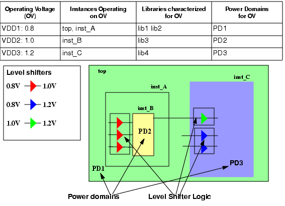
Figure 2-1 shows the typical operating voltage for each power domain. To check if the design functions correctly when slightly different operating conditions apply, typically a multi-corner timing analysis is done for the worst and best case corner. A pure MSV design has only one state of the design, so two views can be considered as shown in Figure 2-2. The design must function correctly in both corners for the same set of timing constraints that is typically specified for a given state of the design (power mode).
Figure 2-2 Multi-Corner Timing Analysis

When analyzing a view of the design, you need to indicate the corners at which the power domains are operating, as shown in Figure 2-3.
Figure 2-3 Relation of Analysis View with Power Domains and Operating Corners
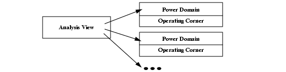
Operating corners are not only characterized by a set of operating conditions, but also by the library sets to be used for that corner, because the timing and power characteristics of the cells depend on the operating conditions. Typically different libraries are used for the different corners.
Table 2-1 indicates for the design of Figure 2-1 the libraries that must be used to analyze the views.
Table 2-1 Operating Corners for the Power Domains of the MSV Design
As it is obvious that all this information is related to the power intent of the design, it makes sense to describe this information in the CPF file.
Complete CPF File for MSV Example
set_cpf_version 1.1
#################################################
#       Technology part of the CPF
#################################################
# define the library sets
define_library_set -name set1_bc -libraries {lib1_bc lib2_bc}
define_library_set -name set1_wc -libraries {lib1_wc lib2_wc}
define_library_set -name set2_bc -libraries lib3_bc
define_library_set -name set2_wc -libraries lib3_wc
define_library_set -name set3_bc -libraries lib4_bc
define_library_set -name set3_wc -libraries lib4_wc
# define the level shifters
define_level_shifter_cell -cells LVLLHEHX* \
   	 -input_voltage_range 0.8 \
   	 -output_voltage_range 1.0 \
   	 -output_power_pin VDD \
   	 -ground VSS \
   	 -direction up \
   	 -valid_location from
define_level_shifter_cell -cells LVLLHX* \
   	 -input_voltage_range 0.8 \
   	 -output_voltage_range 1.2 \
   	 -output_power_pin VDD \
   	 -direction up \
   	 -ground VSS \
   	 -valid_location to
define_level_shifter_cell -cells LVLLHELX* \
   	 -input_voltage_range 1.0 \
   	 -output_voltage_range 1.2 \
   	 -output_power_pin VDD \
   	 -direction up \
   	 -ground VSS \
   	 -valid_location to
#################################################
#       Design part of the CPF
#################################################
set_design top
# create power domains
create_power_domain -name PD1 -default
create_power_domain -name PD2 -instances instance_B
create_power_domain -name PD3 -instances instance_C
# create nominal conditions
create_nominal_condition -name low -voltage 0.8
create_nominal_condition -name medium -voltage 1.0
create_nominal_condition -name high -voltage 1.2
# create power mode
create_power_mode -name PM -domain_conditions {PD1@low PD2@medium PD3@high} \
-default
# associate library sets with nominal conditions
update_nominal_condition -name low -library_set set1_wc
update_nominal_condition -name medium -library_set set2_wc
update_nominal_condition -name high -library_set set3_wc
# create rules for level shifter insertion
create_level_shifter_rule -name lsr1 -from PD1 -to PD2
create_level_shifter_rule -name lsr2 -from PD2 -to PD3
create_level_shifter_rule -name lsr3 -from PD1 -to PD3
#####################################################
# Additional Information for Logic Synthesis
#####################################################
# specify power targets
set_power_target -leakage 30 -dynamic 250
# specify timing constraints
update_power_mode -name PM -sdc_files top.sdc
# specify activity information
update_power_mode -name PM -activity_file top.tcf -activity_file_weight 100
# update the rules
update_level_shifter_rules -names lsr1 -location from
update_level_shifter_rules -names {lsr2 lsr3} -location to
#####################################################
# Additional Information for Physical Implementation
#####################################################
# declare power and ground nets
create_ground_nets -nets VSS
create_power_nets -nets VDD1 -voltage 0.8
create_power_nets -nets VDD2 -voltage 1.0
create_power_nets -nets VDD3 -voltage 1.2
# (optional) create global connections
# create_global_connection -net VSS -pins VSS
# create_global_connection -domain PD1 -net VDD1 -pins VDD
# create_global_connection -domain PD2 -net VDD2 -pins VDD
# create_global_connection -domain PD3 -net VDD3 -pins VDD
# add implementation info for power domains
update_power_domain -name PD1 -primary_power_net VDD1 -primary_ground_net VSS
update_power_domain -name PD2 -primary_power_net VDD2 -primary_ground_net VSS
update_power_domain -name PD3 -primary_power_net VDD3 -primary_ground_net VSS
# create operating corners
create_operating_corner -name BC_PD1 \
   	 -process 1 -temperature 0 -voltage 0.88 -library_set set1_bc
create_operating_corner -name BC_PD2 \
   	 -process 1 -temperature 0 -voltage 1.0 -library_set set2_bc
create_operating_corner -name BC_PD3 \
   	 -process 1 -temperature 0 -voltage 1.32 -library_set set3_bc
create_operating_corner -name WC_PD1 \
   	 -process 1 -temperature 125 -voltage 0.72 -library_set set1_wc
create_operating_corner -name WC_PD2 \
   	 -process 1 -temperature 125 -voltage 0.9 -library_set set2_wc
create_operating_corner -name WC_PD3 \
   	 -process 1 -temperature 125 -voltage 1.08 -library_set set3_wc
# create analysis views
create_analysis_view -name AV_BC -mode PM \
   	 -domain_corners {PD1@BC_PD1 PD2@BC_PD2 PD3@BC_PD3}
create_analysis_view -name AV_WC -mode PM \
   	 -domain_corners {PD1@WC_PD1 PD2@WC_PD2 PD3@WC_PD3}
end_design
Steps to Create the CPF File for MSV Design
This section describes the information to include in a CPF file for an MSV design. The example shown in Figure 2-1 is used throughout this section.
A CPF file has technology-related information and design-related information.
For an MSV design, the technology-related information lists the libraries that you want to use for the design and identifies the library cells that can be used as level shifters.
The design-related information captures the power intent and constraints.
Declaring the Design Described in the CPF File
Specifying the Naming Styles Used
Specifying the Operating Voltages Used in the Design
Associating a Nominal Condition with a Power Domain
Specifying the Libraries to Use for a Condition
Specifying the Rules to Create Level Shifter Logic
Specifying Activity Information
The following information is needed for physical implementation:
Specifying the Global Power and Ground Nets
Specifying the Global Connections
Specifying Additional Information for Power and Ground Routing
Specifying the Operating Corners
Specifying the Libraries
 |
To group libraries that are characterized for a specific set of operating conditions, use the define_library_set command: |
define_library_set -name library_set-librarieslibrary_list
For the example in Figure 2-1, six library sets are defined: one library set for the best and worst case operating conditions of each power domain.
define_library_set -name set1_bc -libraries {lib1_bc lib2_bc}
define_library_set -name set1_wc -libraries {lib1_wc lib2_wc}
define_library_set -name set2_bc -libraries lib3_bc
define_library_set -name set2_wc -libraries lib3_wc
define_library_set -name set3_bc -libraries lib4_bc
define_library_set -name set2_wc -libraries lib3_wc
Specifying the Level Shifter Cells to Use
| |
To identify which cells in the libraries can be used as level shifters, use the define_level_shifter_cell command. |
For more information on how to model different types of level shifters, refer to Modeling Level Shifters.
For applications that do not read .lib files, you must specify the library cells to allow the application to identify the instances of these cells in the netlist.
An MSV design may need different level shifters depending on the voltage gaps to bridge. For the example in Figure 2-1, the following command defines a set of level shifters that can be used from a power domain operating on 0.8V to a power domain operating on1.0V.
define_level_shifter_cell -cells LVLLHEHX* \
   	 -input_voltage_range 0.8 \
   	 -output_power_pin VDD \
   	 -output_voltage_range 1.0 \
   	 -direction up \
   	 -ground VSS \
   	 -valid_location from
Declaring the Design Described in the CPF File
| |
To identify the design for which the CPF file is created, use the following command: |
set_designmodule
where module refers to the name of the top module of the design to which the power information in the CPF file applies.
For the example in Figure 2-1:
set_design top
| |
To indicate when the power information for this module ends, use the following command: |
end_design
Specifying Units Used
You can specify the units that will be used for the power and time values in CPF commands.
| |
To specify the power unit used, use the following command |
| |
To specify the time unit used, use the following command |
Note: These commands are optional if you use the default values.
Specifying the Naming Styles Used
| |
To specify the hierarchy separator used in the CPF file, use the following command |
The format of a name in RTL and in the netlist can be different. When you want to use the RTL names in the CPF file, but you are reading a gate-level netlist, you need to specify how the base name and bit information are represented in the netlist.
| |
To specify the format used to name flip-flops and latches in the netlist starting from the register names in the RTL description, use the following command |
| |
To specify the format used to name the design objects in the netlist starting from multi-bit arrays in the RTL description, use the following command |
For more information on these two commands, refer to Individual Registers Names in the Common Power Format Language Reference.
Note: These three commands are optional if you use the default values.
Specifying the Power Domains
| |
To identify portions of the design that operate on the same voltage, associate these portions with a power domain using the create_power_domain command: |
create_power_domain -name power_domain[-instancesinstance_list] [-boundary_portspin_list] [-default]
Note:
The following options of create_power_domain are irrelevant for a pure MSV (non-switchable) design: -shutoff_condition, external_controlled_shutoff, -default_isolation_condition, -default_restore_edge, -default_save_edge, -default_restore_level, -default_save_level, -power_up_states, -active_state_conditions, and -base_domains.
For the example in Figure 2-1:
create-power_domain -name PD1 -default
create_power_domain -name PD2 -instances inst_B
create_power_domain -name PD3 -instances inst_C
Note: CPF requires that the top module belongs to the default power domain.
Specifying the Operating Voltages Used in the Design
In CPF, operating voltages are associated with nominal conditions.
| |
To specify the operating voltages used in the design, use the create_nominal_condition command: |
create_nominal_condition -name string-voltage {voltage|voltage_list}[-ground_voltage{voltage|voltage_list}]
Note:
The following options of create_nominal_condition are irrelevant for a pure MSV design: -state, -pmos_bias_voltage and -nmos_bias_voltage.
For the example in Figure 2-1 three nominal conditions are defined.
create_nominal_condition -name low -voltage 0.8
create_nominal_condition -name medium -voltage 1.0
create_nominal_condition -name high -voltage 1.2
 | In CPF, operating voltages are not directly associated with power domains. When using other low power techniques such as power shut off (PSO) or dynamic voltage frequency scaling (DVFS), the operating voltage of a power domain can change and different power domains can use the same operating voltage at different times. |
Associating a Nominal Condition with a Power Domain
In CPF, nominal conditions are associated with power domains for a given design mode (here referred to as power mode).
A pure MSV design (a design that uses multiple supply voltages but no other low power techniques such as PSO or DVFS methodology) is considered to have only one power mode and each power domain can be associated with only one nominal condition.
| |
To associate the nominal conditions with the power domains, use the create_power_mode command: |
create_power_mode -name string-domain_conditionsdomain_condition_list-default
Note:
The -group_modes option of the create_power_mode command is only relevant for a hierarchical flow. For more information, refer to Chapter 4, "Hierarchical Flow."
Use the following format to specify a domain condition (association of a power domain with its nominal condition):
domain_name@nominal_condition_name
For the example in Figure 2-1:
create_power_mode -name PM -domain_conditions {PD1@low PD2@medium PD3@high} \
-default
Note: CPF requires that one power mode is specified as the default power mode.
Specifying the Libraries to Use for a Condition
You already grouped libraries that are characterized for a specific set of operating conditions in a library set.
| |
To specify which library set to use for a specific nominal condition, use the update_nominal_condition command: |
update_nominal_condition -name condition-library_setlibrary_set
Typically, you specify here the libraries for the worst case condition. For the example in Figure 2-1:
update_nominal_condition -name low -library_set set1_wc
update_nominal_condition -name medium -library_set set2_wc
update_nominal_condition -name high -library_set set3_wc
Specifying the Rules to Create Level Shifter Logic
Depending on your technology, you may need level shifters when passing any signals
From a power domain with a lower voltage to a power domain with a higher voltage
From a power domain with a higher voltage to a power domain with a lower voltage
In both cases
| |
To create the rule to be used between power domains or a set of pins, use the create_level_shifter_rule command: |
create_level_shifter_rule -name string{-pinspin_list| -frompower_domain_list| -topower_domain_list}...[-excludepin_list]
For the example in Figure 2-1:
create_level_shifter_rule -name lsr1 -from PD1 -to PD2
create_level_shifter_rule -name lsr2 -from PD2 -to PD3
create_level_shifter_rule -name lsr3 -from PD1 -to PD3
Specifying Power Constraints
Note: This information is optional in the CPF file.
| |
To specify the targets for leakage and dynamic power in the current design, use the set_power_target command: |
set_power_target
{ -leakagefloat| -dynamicfloat
| -leakagefloat-dynamicfloat}
For the example in Figure 2-1:
set_power_target -leakage 30 -dynamic 250
Specifying Timing Constraints
Note: This information is optional in the CPF file.
| |
To specify the timing constraints for the current design, use the -sdc_files option of the update_power_mode command: |
update_power_mode -name mode{-sdc_files | -setup_sdc_files | -hold_sdc_files}sdc_file_list
For the example in Figure 2-1:
update_power_mode -name PM -sdc_files top.sdc
Specifying Activity Information
Note: This information is optional in the CPF file.
| |
To specify the activity information that can be used for power analysis, use |
update_power_mode -name mode-activity_filefile-activity_file_weightweight
Supported formats for the activity files are VCD, TCF, and SAIF.
If the design has several modes, you can specify the relative weight of the activities per mode for optimization purpose. Because an MSV design has only one power mode, the weight for the file must be 100.
For the example in Figure 2-1:
update_power_mode -name PM -activity_file top.tcf -activity_file_weight 100
Updating the Rules with Implementation Information
You can specify additional information for level shifters, such as, where to place them, what cells to use, or what prefix to use for the added level shifters in the design.
| |
To specify the location or the type of level shifters to be used, use the update_level_shifter_rules command: |
update_level_shifter_rules -names rule_list
{ -location {from | to | parent | any}
| -within_hierarchyinstance| -cells cell_list
| -prefixstring}...
For the example in Figure 2-1:
update_level_shifter_rules -names lsr1 -location from
update_level_shifter_rules -names {lsr2 lsr3} -location to
Specifying the Global Power and Ground Nets
| |
To declare (or create) the nets connected to the power supplies, use the create_ground_nets and commands: |
create_ground_nets -nets net_list[-voltagestring]
[-user_attributesstring_list]
[-peak_ir_drop_limitfloat]
[-average_ir_drop_limitfloat]
create_power_nets -nets net_list[-voltagestring]
[-user_attributesstring_list]
[-peak_ir_drop_limitfloat]
[-average_ir_drop_limitfloat]
Note:
The following options of create_ground_nets and create_power_nets are irrelevant for the pure MSV design: -external_shutoff_condition, and -internal.
For the example in Figure 2-1:
create_ground_nets -nets VSS
create_power_nets -nets VDD1 -voltage 0.8
create_power_nets -nets VDD2 -voltage 1.0
create_power_nets -nets VDD3 -voltage 1.2
Specifying the Global Connections
| |
To specify how to connect global nets, such as power and ground nets, use the create_global_connection command: |
create_global_connection
-netnet-pinspin_list
[-domaindomain| -instancesinstance_list]
For the example in Figure 2-1:
create_global_connection -net VSS -pins VSS
create_global_connection -domain PD1 -net VDD1 -pins VDD
create_global_connection -domain PD2 -net VDD2 -pins VDD
create_global_connection -domain PD3 -net VDD3 -pins VDD
Specifying Additional Information for Power and Ground Routing
| |
To specify additional information that applies to power and ground routing, use |
update_power_domain
-namedomain{ -primary_power_netnet| -primary_ground_netnet} ...
For the example in Figure 2-1:
update_power_domain -name PD1 -primary_power_net VDD1
update_power_domain -name PD2 -primary_power_net VDD2
update_power_domain -name PD3 -primary_power_net VDD3
Here the update_power_domain command for power domain PD1 indicates that VDD1 is the main power net for all cells of power domain PD1.
Specifying the Operating Corners
The design must be able to perform under different sets of operating conditions (process, voltage, and temperature values). Because the timing and power characteristics of the cells depend on the operating conditions, different library sets that contain the characterization information for the different conditions are used. An operating corner shows which library set to use for a given operating condition.
| Different portions of the design can operate at the same voltage and yet use dedicated library sets. In this case, it is possible to have multiple operating corners with the same operating conditions. |
| |
To define an operating corner, use the create_operating_corner command. |
create_operating_corner
-namestring-voltagefloat[-ground_voltagefloat]
[-processfloat]
[-temperaturefloat]
-library_setlibrary_set
Note:
The -pmos_bias_voltage and -nmos_bias_voltage options of create_operating_corner are irrelevant for a design not using substrate biasing.
For the design in Figure 2-1, six operating corners were specified.
The following command specifies to use library set set1_bc for operating corner BC_PD1. The process value of the operating corner is 1, the temperature is 0°C and the operating voltage is 0.88V. This operating corner is defined for best case conditions.
create_operating_corner -name BC_PD1 \
   	 -process 1 -temperature 0 -voltage 0.88 -library_set set1_bc
Specifying the Analysis Views
The design must function correctly in each power mode not only under typical conditions, but also under extreme conditions. Typically a multi-mode multi-corner timing analysis will be done for the worst case and the best case conditions.
An analysis view associates a specific operating corner with each power domain in the specified power mode. You need to make sure that all operating corners for a view correspond to either best or worst case conditions.
| |
To define an analysis view, use the create_analysis_view command. |
create_analysis_view
-namestring-modemode-domain_cornersdomain_corner_list[-user_attributesstring_list]
Note:
The -group_views option of create_analysis_view is only relevant in a hierarchical flow. For more information, refer to Chapter 4, "Hierarchical Flow."
Use the following format to specify a domain corner:
| The CPF file can contain several analysis views with the same domain and corner information for a power mode. For a multi-mode multi-corner analysis, some implementation and timing analysis tools need unique views to associate with different parasitic corners. |
For the design in Figure 2-1, two analysis views were specified.
The following command specifies analysis view AV_BC for power mode PM1. For this view the operating corners for the best case operating conditions are associated with the three power domains.
create_analysis_view -name AV_BC -mode PM1 \
   	 -domain_corners {PD1@BC_PD1 PD2@BC_PD2 PD3@BC_PD3}
Creating a CPF File for a Design Using PSO Methodology
A design using power shut off (PSO) implementation is a design of which some portions can be switched on and off as needed (or possibly) to save leakage and dynamic power.
Logic blocks (hierarchical instances), leaf instances, and pins that use the same main power supply and that can be simultaneously switched on or off are said to belong to the same power domain. The example design in Figure 2-4 has three power domains:
The top-level of the design,
top, and hiearchical instances,inst_Candpm_inst,are always switched on: they belong to domainPD1Hierarchical instances
inst_Aandinst_Bare always switched on and off simultaneously: they belong to power domainPD2Hierarchical instance
inst_Dcan be switched on and off independently from hierarchical instancesinst_Aandinst_B:it belongs to power domainPD3
Figure 2-4 Example of Design with PSO
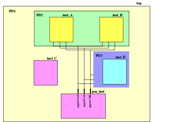
Power domain PD1 is never powered down. It is called an unswitched domain.
Power domains PD2 and PD3 can be powered down. They are referred to as switchable domains. CPF distinguishes between internal switchable, and on-chip controlled external switchable domains.
A steady state of the design in which some power domains are switched on and some power domains are switched off is called a power mode. In a power mode, each power domain operates on a specific nominal condition. Different timing constraints can be associated with each power mode. Table 2-2 shows the three power modes of the example design.
Table 2-2 Power Modes
Note: A voltage of 0.0V indicates that the power domain is off.
To prevent that unknown states in the power domains that are powered down propagate to the domains that remain powered on isolation cells are needed at the boundaries of the power domains that are powered down. Most of the time, isolation cells are inserted at the output boundaries of the powered down domains. You can, however, also insert isolation cells at the input boundaries.
To facilitate powered down blocks to resume normal operation, state retention cells can be used for some sequential cells to keep their previous state prior to power down.
For switchable domains you need to indicate how the power supply is connected and disconnected from the gates.
For internal switchable domains, you must add power switch logic.
For external switchable domains, the power switch logic is not part of the chip, so you must indicate that an external power shut-off method is used.
For this example we are assuming that power domains PD2 and PD3 are internal switchable.
Special control signals are used to shut down a power domain, enable state retention, and control the working of the power switch logic. Table 2-3 shows the signals used in this example.
Table 2-3 Signals Controlling the Power Domains
When a domain is switchable, it derives its power from another power domain through either internal or external power switch logic.
In this example, power domain PD2 derives its power from power domain PD1, then PD1 is called the secondary (or base) domain for PD2, which is referred to as the primary (or derived) domain.
When defining a (primary) power domain you can indicate its secondary domain and under which condition the domain will be shut down.
The majority of instances in a power domain are driven by the same power supply. For switchable domains, it is the primary power and ground nets of the (primary) power domain to which the instances belong that provide the power supply to the power and ground pins (follow-pins) of the cells.
On the other hand, isolation cells and state retention cells are driven by multiple power supplies. These special low power instances have at least two sets of power and ground pins, and are therefore associated with two power domains: the primary domain is the domain that provides the power supply to their primary set of power and ground pins. The secondary domain is the domain whose primary power and ground nets provide the power supply to the secondary power and ground pins of the special low power instances.
It is recommended that you specify the secondary domain for these special low power instances, but if you do not specify this information, the tools can use some rules to derive the secondary domain. For more information, refer to Secondary Power Domain of Isolation Instances, and Secondary Domain of Retention Logic.
If the design can operate in different power modes, you need to check if the design functions correctly in each of these modes not only at the typical conditions but also when slightly different operating conditions apply. Typically a multi-mode multi-corner timing analysis will be done for the worst case and the best case corner. The design must function correctly in both corners for the same set of timing constraints that is specified for that power mode. Figure 2-5 shows that an analysis (view) can be done for each corner of the power mode.
Figure 2-5 Multi-Corner Timing Analysis for a Power Mode

When analyzing a view of the design, you need to indicate the corners at which the power domains are operating, as shown in Figure 2-6.
Figure 2-6 Relation of Analysis View with Power Domains and Operating Corners

Operating corners are not only characterized by a set of operating conditions, but also by the library sets to be used for that corner, because the timing and power characteristics of the cells depend on the operating conditions. Typically different libraries are used for the different corners.
Table 2-4 indicates which library sets must be used for the design in Figure 2-4 to check the conditions.
Table 2-4 Operating Corners
As is obvious that all this information is related to the power intent of the design, it makes sense to describe this information in the CPF file.
Complete CPF File for PSO Example
set_cpf_version 1.1
#################################################
#       Technology part of the CPF
#################################################
# define the library sets
define_library_set -name set1_wc -libraries {lib1_wc lib2_wc}
define_library_set -name set1_bc -libraries {lib1_bc lib2_bc}
# define the isolation cells
define_isolation_cell -cells ISOLN* -enable EN -valid_location on
# define the always on cell
define_always_on_cell -cells "BUFGX2M BUFGX8M INVGX2M INVGX8M"
# define the state retention cell
define_state_retention_cell -cells *DRFF* -restore_function RETN
# define the power switch cells
define_power_switch_cell -cells "hd8DM hd16DM hd32DM hd64DM"  \
   	 -stage_1_enable SLEEP -type header
define_power_switch_cell -cells "hd8M hd16M hd32M hd64M"  \
   	 -stage_1_enable !SLEEP -type header
define_power_switch_cell -cells "ft8DM ft16DM" \
   	 -stage_1_enable !SLEEPN -type footer
define_power_switch_cell -cells "ft8M ft16M"  \
   	 -stage_1_enable SLEEPN -type footer
#################################################
#       Design part of the CPF
#################################################
# identify the design for which the CPF file is created
set_design top
# create power domains
create_power_domain -name PD1 -default
create_power_domain -name PD2 -instances {inst_A inst_B} \
-shutoff_condition {pse_enable[0]} -base_domains PD1
create_power_domain -name PD3 -instances inst_D \
-shutoff_condition {pse_enable[1]} -base_domains PD1
# create nominal conditions
create_nominal_condition -name off -voltage 0
create_nominal_condition -name on -voltage 1.1
# create power modes
create_power_mode -name PM1 -domain_conditions {PD1@on PD2@on PD3@on} -default
create_power_mode -name PM2 -domain_conditions {PD1@on PD3@on}
create_power_mode -name PM3 -domain_conditions {PD1@on}
# associate library sets with nominal conditions
update_nominal_condition -name on -library_set set1_wc
# create rules for isolation logic insertion
create_isolation_rule -name iso1 -from PD2 \
-isolation_condition {pm_inst.ice_enable[0]}
create_isolation_rule -name iso2 -to PD1\
-isolation_condition {pm_inst.ice_enable[1]} -isolation_output high
# create rules for state retention insertion
create_state_retention_rule -name st1 -domain PD2 \
-restore_edge {!pm_inst.pge_enable[0]}
create_state_retention_rule -name st2 -domain PD3 \
-restore_edge {!pm_inst.pge_enable[1]}
#####################################################
# Additional Information for Logic Synthesis
#####################################################
# specify power targets
set_power_target -leakage 30 -dynamic 250
# specify timing constraints
update_power_mode -name PM1 -sdc_files pm1.sdc
update_power_mode -name PM2 -sdc_files pm2.sdc
update_power_mode -name PM1 -activity_file top.tcf -activity_file_weight 100
# update the rules with implementation info
update_isolation_rules -names iso1 -location to -cells ISOLNX2M
update_isolation_rules -names iso2 -location to -cells ISOLNX2M
#####################################################
# Additional Information for Physical Implementation
#####################################################
# declare power and ground nets
create_power_nets -nets VDD -voltage 1.1
create_power_nets -nets {VDD_SW1 VDD_SW2} -internal
create_ground_nets -nets VSS -voltage 0
# (optional) create global connections
create_global_connection -net VDD -pins VDD
create_global_connection -net VSS -pins VSS
# rules for power switch insertion
create_power_switch_rule -name SW1 -domain PD2 -external_power_net VDD
create_power_switch_rule -name SW2 -domain PD3 -external_power_net VDD
update_power_switch_rule -name SW1 -cells hd32M -prefix CDN_
update_power_switch_rule -name SW2 -cells hd32M -prefix CDN_
# add implementation info for power domains
update_power_domain -name PD1 -primary_power_net VDD -primary_ground_net VSS
update_power_domain -name PD2 -primary_power_net VDD_SW1 -primary_ground_net VSS
update_power_domain -name PD3 -primary_power_net VDD_SW2 -primary_ground_net VSS
# create operating corners
create_operating_corner -name BC \
   	 -process 1 -temperature 0 -voltage 1.21 -library_set set1_bc
create_operating_corner -name WC \
   	 -process 1 -temperature 125 -voltage 0.99 -library_set set1_wc
# create analysis views
create_analysis_view -name AV_PM1_bc -mode PM1 \
   	 -domain_corners {PD1@BC PD2@BC PD3@BC}
create_analysis_view -name AV_PM1_wv -mode PM1 \
   	 -domain_corners {PD1@WC PD2@WC PD3@WC}
create_analysis_view -name AV_PM2_bc -mode PM2 \
   	 -domain_corners {PD1@BC PD2@BC PD3@BC}
create_analysis_view -name AV_PM2_wc -mode PM2 \
   	 -domain_corners {PD1@WC PD2@WC PD3@WC}
create_analysis_view -name AV_PM3_bc -mode PM3 \
   	 -domain_corners {PD1@BC PD2@BC PD3@BC}
create_analysis_view -name AV_PM3_wc -mode PM3 \
   	 -domain_corners {PD1@WC PD2@WC PD3@WC}
# indicate when the power information for the design ends
end_design
Steps to Create the CPF File for Design Using PSO
This section describes the information to include in a CPF file for a design using the PSO methodology. The example shown in Figure 2-4 is used throughout this section.
A CPF file has technology-related information and design-related information.
For a design using the PSO methodology, the technology-related information lists the libraries that you want to use for the design and identifies the library cells that can be used as isolation cells, power switch cells and state retention cells.
Specifying the Isolation Cells to Use
Specifying the Always-On Cells
Specifying the State Retention Cells to be Used
The design-related information captures the power intent and constraints.
Declaring the Design Described in the CPF File
Specifying the Operating Voltage Used in the Design
Specifying the Static Behavior in each Power Mode
Specifying the Libraries to Use for a Condition
Specifying the Rules to Create Isolation Logic
Specifying the Rules to Create State Retention Logic
Specifying Activity Information
The following information is needed for physical implementation:
Specifying the Power and Ground Nets
Specifying the Global Connections
Specifying the Rules for the Power Switch Logic
Specifying Additional Information for Power and Ground Routing
Specifying the Operating Corners
Specifying the Libraries
| |
To group libraries that are characterized for a specific set of operating conditions, use the define_library_set command: |
define_library_set -name library_set-librarieslibrary_list
For the example in Figure 2-4, we assume only one main power supply, which implies that the definition of one library set is sufficient.
define_library_set -name set1_wc -libraries {lib1_wc lib2_wc}
define_library_set -name set1_bc -libraries {lib1_bc lib2_bc}
Specifying the Isolation Cells to Use
| |
To identify which cells in the libraries can be used as isolation cells, use the define_isolation_cell command. |
For more information on how to model different types of isolation cells, refer to Modeling Isolation Cells.
For applications that do not read .lib files, you must specify these library cells to allow these applications to identify instances of isolation cells in the netlist.
For the example in Figure 2-4:
define_isolation_cell -cells ISOLN* -enable EN -valid_location on
Specifying the Always-On Cells
Always-on cells are special cells whose power supply has to be continuous on even when the power supply for the rest of the logic in the power domain is off.
Always-on cells are used for example
To drive the control signals of the state retention cells in a domain that is being powered down
In combination with isolation cells that are inserted in the power domain that is switched off to ensure that the driver of the enable pin of the isolation cells is never switched off.
| |
To identify which cells in the libraries can be used as always-on cells, use the define_always_on_cell command. |
define_always_on_cell
-cellscell_list[-library_setlibrary_set]
[ {-power_switchableLEF_power_pin
|-ground_switchableLEF_ground_pin|-power_switchableLEF_power_pin-ground_switchableLEF_ground_pin}
-powerLEF_power_pin-groundLEF_ground_pin]
Note: Outputs of cells that are always on, are always-on drivers.
For applications that do not read .lib files, you must specify these library cells to allow these applications to identify the instances of these cells in the netlist.
For the example in Figure 2-4,
define_always_on_cell -cells "BUFGX2M BUFGX8M INVGX2M INVGX8M"
Specifying the State Retention Cells to be Used
| |
To identify which cells in the libraries can be used as state retention cells, use the define_state_retention_cell command. |
For more information on how to model different types of state retention cells, refer to Modeling State Retention Cells.
For applications that do not read .lib files, you must specify these library cells to allow these applications to identify the instances of these cells in the netlist.
For the example in Figure 2-4,
define_state_retention_cell -cells *DRFF* -restore_function RETN
This command indicates that when the restore pin RETN is set to 1, the state of the specified cells will be restored to the value saved after exiting power shut-off mode.
Specifying the Power Switch Cells to be Used
| |
To identify which cells in the libraries can be used as power switch cells, use the define_power_switch_cell command. |
For more information on how to model different types of power switch cells, refer to Modeling Power Switch Cells.
For applications that do not read .lib files, you must specify the library cells to allow the applications to identify the instances of these cells in the netlist.
For the example in Figure 2-4,
define_power_switch_cell -cells "hd8DM hd16DM hd32DM hd64DM"  \
   	 -stage_1_enable SLEEP -type header
define_power_switch_cell -cells "hd8M hd16M hd32M hd64M"  \
   	 -stage_1_enable !SLEEP -type header
define_power_switch_cell -cells "ft8DM ft16DM" \
   	 -stage_1_enable !SLEEPN -type footer
define_power_switch_cell -cells "ft8M ft16M"  \
   	 -stage_1_enable SLEEPN -type footer
Declaring the Design Described in the CPF File
| |
To identify the design for which the CPF file is created, use the following command: |
set_designmodule
where module refers to the name of the top module of the design to which the power information in the CPF file applies.
For the example in Figure 2-4:
set_design top
| |
To indicate when the power information for this module ends, use the following command: |
end_design
Specifying Units Used
You can specify the units that will be used for the power and time values in CPF commands.
| |
To specify the power unit used, use the following command |
| |
To specify the time unit used, use the following command |
Note: These commands are optional if you use the default values.
Specifying Naming Styles Used
| |
To specify the hierarchy separator used in the CPF file, use the following command |
The format of a name in RTL and in the netlist can be different. When you want to use the RTL names in the CPF file, but you are reading a gate-level netlist, you need to specify how the base name and bit information are represented in the netlist.
| |
To specify the format used to name flip-flops and latches in the netlist starting from the register names in the RTL description, use the following command |
| |
To specify the format used to name the design objects in the netlist starting from multi-bit arrays in the RTL description, use the following command |
For more information on these two commands, refer to Individual Registers Names in the Common Power Format Language Reference.
Note: These three commands are optional if you use the default values.
Specifying the Power Domains
| |
To identify portions of the design that operate on the same voltage and that can be simultaneously switched on or off, associate these portions with a power domain using the create_power_domain command: |
create_power_domain -name power_domain[-instancesinstance_list] [-boundary_portspin_list] [-default]
[-shutoff_conditionexpression[-external_controlled_shutoff]]
[ -default_isolation_conditionexpression]
[-default_restore_edgeexpr| -default_save_edgeexpr
|-default_restore_edgeexpr-default_save_edgeexpr
|-default_restore_levelexpr-default_save_levelexpr]
[ -power_up_states {high|low|random} ]
[ -active_state_conditionsactive_state_condition_list]
[ -base_domainsdomain_list]
The -shutoff_condition determines when the power domain is switched off. If this option is not specified, the power domain is an unswitched domain.
For the example in Figure 2-4:
create-power_domain -name PD1 -default
create_power_domain -name PD2 -instances {inst_A inst_B} \
-shutoff_condition {pse_enable[0]} -base_domains PD1
create_power_domain -name PD3 -instances inst_D \
-shutoff_condition {pm_inst.pse_enable[1]} -base_domains PD1
Power domains PD2 and PD3 have power domain PD1 as their secondary power domain.
Note: CPF requires that the top module belongs to the default power domain.
Specifying the Operating Voltage Used in the Design
In CPF, operating voltages are associated with nominal conditions.
| |
To specify the operating voltages used in the design, use the create_nominal_condition command: |
create_nominal_condition -name string-voltage {voltage|voltage_list}[-state {on | off | standby}]
[-ground_voltage{voltage|voltage_list}]
Note:
The -pmos_bias_voltage and -nmos_bias_voltage options of create_nominal_condition are irrelevant for a design not using substrate biasing.
The example in Figure 2-4 uses only one operating voltage, but you can also specify a nominal condition whose voltage is 0.
create_nominal_condition -name off -voltage 0
create_nominal_condition -name on -voltage 1.1
Specifying the Static Behavior in each Power Mode
| |
To define the static behavior of the design in a power mode, you need to specify the nominal condition of each power domain in that mode, using the create_power_mode command: |
create_power_mode -name string
-domain_conditionsdomain_condition_list[-default]
Note:
The -group_modes option of the create_power_mode command is only relevant for a hierarchical flow. For more information, refer to Chapter 4, "Hierarchical Flow."
Use the following format to specify a domain condition (association of a power domain with its nominal condition in the power mode being defined):
domain_name@nominal_condition_name
For the example in Figure 2-4:
create_power_mode -name PM1 -domain_conditions {PD1@on PD2@on PD3on} -default
create_power_mode -name PM2 -domain_conditions {PD1@on PD3@on}
create_power_mode -name PM3 -domain_conditions {PD1@on}
Note: CPF requires that one power mode is specified as the default power mode.
Note:
When a domain is not specified in the list of domain conditions, it is considered to be switched off in the specified mode. For example, power domain PD2 is not specified in the list of conditions for power mode PM2, but referring to Table 2-2, power domain PD2 is switched off in this mode. It is recommended not to rely on the default behavior and to specify all power domains when defining a power mode.
Specifying the Libraries to Use for a Condition
You already grouped libraries that are characterized for a specific set of operating conditions in a library set.
| |
To specify which library set to use for a specific nominal condition, use the update_nominal_condition command: |
update_nominal_condition -name condition-library_setlibrary_set
For the example in Figure 2-4:
update_nominal_condition -name on -library_set set1_wc
Specifying the Rules to Create Isolation Logic
| |
To define when isolation cells must be added or to specify which pins must be isolated, use the create_isolation_rule command: |
create_isolation_rule
-namestring[-isolation_conditionexpression| -no_condition]
{-pinspin_list| -frompower_domain_list| -topower_domain_list}...[-exclude
pin_list][-isolation_target{from|to}]
[-isolation_output { high | low | hold | tristate}]
[-secondary_domainpower_domain]
Typically, isolation logic is needed to isolate signals going from a power domain being switched down to a power domain that remains on. If an input of a powered down domain requires a stable signal for electrical reasons, isolation is required even if the signal goes from a powered on domain to a powered down domain.
Referring to Table 2-2, isolation logic will be needed in power modes 2 and 3 for any nets going from power domain PD2 to PD1 and PD3, and for any nets going from power domains PD3 and PD2 to PD1.
For the example in Figure 2-4:
create_isolation_rule -name iso1 -from PD2 \
-isolation_condition {pm_inst.ice_enable[0]}
create_isolation_rule -name iso2 -to PD1\
-isolation_condition {pm_inst.ice_enable[1]} -isolation_output high
In this example, the secondary power domain was not specified for the isolation instances. In this case, the tools will use the power domain of the logic that drives the enable pins. That logic is the pm_inst instance which belongs to power domain PD1.
Specifying the Rules to Create State Retention Logic
| |
To define the rule for replacing selected registers or all registers in the specified power domain with state retention registers, use the create_state_retention_rule command. |
create_state_retention_rule
-namestring{ -domainpower_domain| -instancesinstance_list}[ -excludeinstance_list]
[-restore_edgeexpr| -save_edgeexpr
|-restore_edgeexpr-save_edgeexpr
|-restore_levelexpr-save_levelexpr]
[ -restore_preconditionexpr] [-save_preconditionexpr]
[-target_type {flop|latch|both}]
[-secondary_domaindomain]
For the example in Figure 2-4:
create_state_retention_rule -name st1 -domain PD2 \
-restore_edge {!pm_inst.pge_enable[0]}
create_state_retention_rule -name st2 -domain PD3 \
-restore_edge {!pm_inst.pge_enable[1]}
In this example, the secondary power domain was not specified for the state retention logic. In this case, the tools will use the secondary (or base) power domain of its primary domain. That logic is the pm_inst instance which belongs to power domain PD1.
Specifying Power Constraints
Note: This information is optional in the CPF file.
| |
To specify the targets for leakage and dynamic power in the current design, use the set_power_target command: |
set_power_target
{ -leakagefloat| -dynamicfloat
| -leakagefloat-dynamicfloat}
For the example in Figure 2-4:
set_power_target -leakage 30 -dynamic 250
Specifying Timing Constraints
Note: This information is optional in the CPF file.
| |
To specify the timing constraints for the current design, use the -sdc_files option of the update_power_mode command: |
update_power_mode -name mode{-sdc_files | -setup_sdc_files | -hold_sdc_files}sdc_file_list
For the example in Figure 2-4:
update_power_mode -name PM1 -sdc_files pm1.sdc
update_power_mode -name PM2 -sdc_files pm2.sdc
Specifying Activity Information
Note: This information is optional in the CPF file.
| |
To specify the activity information that can be used for power analysis, use |
update_power_mode -name mode-activity_filefile-activity_file_weightweight
Supported formats for the activity files are VCD, TCF, and SAIF.
If the design has several modes, you can specify the relative weight of the activities per mode.
For the example in Figure 2-4, only the activity file for the default power mode is specified:
update_power_mode -name PM1 -activity_file top.tcf -activity_file_weight 100
Updating the Rules with Information for Implementation
To specify the location or the type of isolation cells to be used, use the
update_isolation_rulescommand:To append the specified rules for state retention logic with implementation information, use the
update_state_retention_rulescommand:
For the example in Figure 2-4:
update_isolation_rules -names iso1 -location to -cells ISOLNX2M
update_isolation_rules -names iso2 -location to -cells ISOLNX2M
Specifying the Power and Ground Nets
| |
To declare (or create) the nets connected to the power supplies, use the create_ground_nets and create_power_nets commands: |
create_ground_nets -nets net_list[-voltagestring]
[-external_shutoff_conditionexpression| -internal]
[-user_attributesstring_list]
[-peak_ir_drop_limitfloat]
[-average_ir_drop_limitfloat]
create_power_nets -nets net_list[-voltagestring]
[-external_shutoff_conditionexpression| -internal]
[-user_attributesstring_list]
[-peak_ir_drop_limitfloat]
[-average_ir_drop_limitfloat]
Note:
Power and ground nets referenced in an update_power_domain command can be either always on or can be switchable power nets depending on the power domain specification. Other power and ground nets are considered to be always on unless you specify the -external_shutoff_condition option.
For the example in Figure 2-4,
create_power_nets -nets VDD -voltage 1.1
create_power_nets -nets {VDD_SW1 VDD_SW2} -internal
create_ground_nets -nets VSS -voltage 0
Specifying the Global Connections
| |
To specify how to connect global nets, such as power and ground nets, use the create_global_connection command: |
create_global_connection
-netnet-pinspin_list
[-domaindomain| -instancesinstance_list]
For the example in Figure 2-4:
create_global_connection -net VDD -pins VDD
create_global_connection -net VSS -pins VSS
Specifying the Rules for the Power Switch Logic
To specify how a single power switch must connect the external and internal power or ground nets for the specified power domain, use the
create_power_switch_rulecommand.To append the specified rules for power switch logic with implementation information, use the
update_power_switch_rulecommand:
For the example in Figure 2-4:
create_power_switch_rule -name SW1 -domain PD2 -external_power_net VDD
create_power_switch_rule -name SW2 -domain PD3 -external_power_net VDD
update_power_switch_rule -name SW1 -cells hd32M -prefix CDN_
update_power_switch_rule -name SW2 -cells hd32M -prefix CDN_
Specifying Additional Information for Power and Ground Routing
| |
To specify additional information that applies to power and ground routing, use |
update_power_domain
-namedomain{ -primary_power_netnet| -primary_ground_netnet} ...
For the example in Figure 2-4:
update_power_domain -name PD1 -primary_power_net VDD -primary_ground_net VSS
update_power_domain -name PD2 -primary_power_net VDD_SW1 -primary_ground_net VSS
update_power_domain -name PD3 -primary_power_net VDD_SW2 -primary_ground_net VSS
Specifying the Operating Corners
The design must be able to perform under different sets of operating conditions (process, voltage, and temperature values). Because the timing and power characteristics of the cells depend on the operating conditions, different library sets that contain the characterization information for the different conditions are used. An operating corner shows which library set to use for a given operating condition.
| Different portions of the design can operate at the same voltage and yet use dedicated library sets. In this case, it is possible to have multiple operating corners with the same operating conditions. Table 2-4 illustrates this case. |
| |
To define an operating corner, use the create_operating_corner command. |
create_operating_corner
-namestring-voltagefloat[-ground_voltagefloat]
[-processfloat]
[-temperaturefloat]
-library_setlibrary_set
Note:
The -pmos_bias_voltage and -nmos_bias_voltage options of create_operating_corner are irrelevant for a design not using substrate biasing.
For the design in Figure 2-4, two operating corners were specified.
The following command specifies to use library set set1_wc for operating corner WC. The process value of the operating corner is 1, the temperature is 125°C and the operating voltage is 0.99V. This operating corner is defined for worst case conditions.
create_operating_corner -name WC \
   	 -process 1 -temperature 125 -voltage 0.99 -library_set set1_wc
Specifying the Analysis Views
The design must function correctly in each power mode not only under typical conditions, but also under extreme conditions. Typically a multi-mode multi-corner timing analysis will be done for the worst case and the best case conditions.
An analysis view associates a specific operating corner with each power domain in the specified power mode. You need to make sure that all operating corners for a view correspond to either best or worst case conditions.
| |
To define an analysis view, use the create_analysis_view command. |
create_analysis_view
-namestring-modemode-domain_cornersdomain_corner_list[-user_attributesstring_list]
Note:
The -group_views option of create_analysis_view is only relevant in a hierarchical flow. For more information, refer to Chapter 4, "Hierarchical Flow."
Use the following format to specify a domain corner:
| The CPF file can contain several analysis views with the same domain and corner information for a power mode. For a multi-mode multi-corner analysis, some implementation and timing analysis tools need unique views to associate with different parasitic corners. |
For the design in Figure 2-7, six analysis views were specified.
The following command specifies analysis view AV_PM1 for power mode PM1. For this view the operating corners for the best case operating conditions are associated with the three power domains.
create_analysis_view -name AV_PM1 -mode PM1 \
   	 -domain_corners {PD1@BC PD2@BC PD3@BC}
Creating a CPF File for a Design Using DVFS Methodology
Dynamic voltage frequency scaling (DVFS) reduces the power in the chip by scaling down the voltage and frequency when peak performance is not required.
A design using DVFS can be seen as a special case of an MSV design operating in multiple design modes.
In a pure MSV design different portions of the design operate on different voltages and these portions remain operating at their respective operating voltage.
In a DVFS design, in addition some portions can dynamically change to other voltages depending on the design mode or can even be switched off.
Requirements for DVFS Designs
DVFS designs require variable power supply(ies) that can generate the required voltage levels with minimal transition energy losses and a quick voltage transient response.
When scaling the voltage, the frequency must be scaled accordingly to meet signal propagation delay requirements.
A power scheduler can intelligently compute the appropriate frequency and voltage levels needed to execute the various applications.
Figure 2-7 Example of DVFS Design
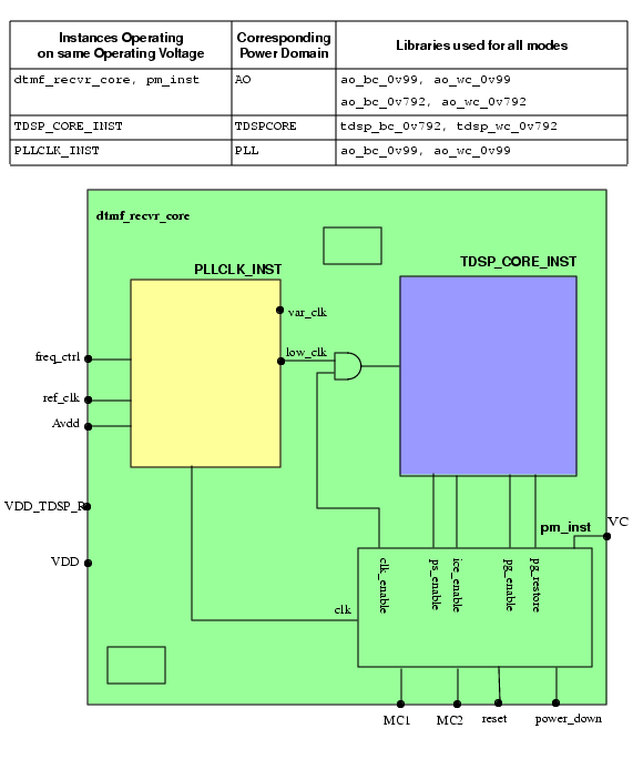
The dtmf_recvr_core design shown in Figure 2-7 has several other blocks which for the sake of simplicity are not shown here. However, they all operate at the same voltage as the top-level of the design.
The voltage of the top-level design is scaled depending on the requested function of the design. If the processing speed is critical a higher voltage is used, if the processing speed is not critical, the voltage is dynamically scaled down together with the clock frequency to save power. For this design we assume that the voltage supply is dynamically controlled external to the chip. The input power signal for the top-level and the blocks that operate at the same voltage is VDD.
Note: The design used here uses both DVFS and PSO methodology.
The dtmf_recvr_core design further contains
The
TDSP_CORE_INSTblockThis digital signal processing block operates at a lower voltage because its processing speed is not critical. When the block does not need to be operational, it is shut down.
The power input for this block is
Vdd_TDSP_R. Theclk_enablesignal disables the clock when the block is shut down.The
PLLCLK_INSTblockThis block is used to generate the clocks needed by all the blocks in the design. It has a reference clock,
ref_clk, that is used to generate all other clocks.Because the design uses two operating voltages, two clock signals are created:
The
low_clkclock signal which feeds theTDSP_CORE_INSTblock has a constant lower frequency.The
var_clkclock signal feeds the top-level design and other blocks and can vary in clock frequency depending on the operating voltage.
The
freq_ctrlsignal ensures that the frequency of thevar_clksignal used for the top-level design is scaled proportional to the voltage.Because this block is an analog block, it needs to operate at a constant voltage to ensure correct working. It therefore needs a dedicated power input,
Avdd.The
pm_instblock
In DVFS designs, a collection of logic blocks (hierarchical instances) and leaf instances that use the same main power supply and whose voltage and frequency can simultaneously change or be switched off belong to the same power domain.
The example design in Figure 2-7 has the following power domains.
The
PLLCLK_INSTblock is the only block in the design that operates at constant voltage 0.99V. This block belongs to power domainPLL.The
TDSP_CORE_INSTblock operates at voltage 0.792V and it is the only block that is shut down at certain times. This block belongs to power domainTDSPCORE.The
pm_instblock, the top-level design and the remaining blocks are always powered on but their operating voltage and frequency can change. They belong to power domainAO.
Power domains PLL and AO are never powered down. They are referred to as an unswitched domain. Power domain TDSPCORE can be powered down and is called a switchable domain. CPF distinguishes between internal switchable, and on-chip controlled external switchable domains.
A steady state of a design in which some power domains are switched on and some power domains are switched off is called a power mode. In a power mode, each power domain operates on a specific voltage (nominal condition). Table 2-5 shows the operating voltages for each of the power domains in the three power modes of the dtmf_recvr_core design. The voltages shown in this table correspond to the worst case voltages. The typical voltages for the design would be 1.1V and 0.88V.
Table 2-5 Power Modes
To pass signals between portions of the design that operate on different voltages, level shifters are needed.
To prevent unknown states from propagating from a power domain that is powered-down to a power domain that remains on, isolation cells are needed at the boundaries of the power domains that are powered down. Most of the time, isolation cells are inserted at the output boundaries of the powered down domains. You can, however, also insert isolation cells at the input boundaries.
To facilitate powered down blocks to resume normal operation, state retention cells can be used for some sequential cells to keep their previous state prior to power up.
To connect and disconnect the power supply from the gates in a power domain, you must add power switch logic or use an external power shut-off method.
For switchable domains you need to indicate how the power supply is connected and disconnected from the gates.
For internal switchable domains, you must add power switch logic.
For external switchable domains, the power switch logic is not part of the chip, so you must indicate that an external power shut-off method is used.
For this example we are assuming that power domain TDSPCore is internal switchable.
Special control signals are used to control the supply voltage, shut down a power domain, enable state retention, restore the state of the registers when powering up a power domain, and control the working of the power switch logic. Table 2-6 shows the signals used in this design example.
Table 2-6 Signals Controlling the Power Domains
When a domain is switchable, it derives its power from another power domain through either internal or external power switch logic.
In this example, power domain TDSPCore derives its power from power domain AO, then AO is called the secondary (or base) domain for TDSPCore, which is referred to as the primary (or derived) domain.
When defining a (primary) power domain you can indicate its secondary domain and under which condition the domain will be shut down.
The majority of instances in a power domain are driven by the same power supply. For switchable domains, it is the primary power and ground nets of the (primary) power domain to which the instances belong that provide the power supply to the power and ground pins (follow-pins) of the cell.
On the other hand, level shifters, isolation cells and state retention cells are driven by multiple power supplies. These special low power instances have at least two sets of power and ground pins, and are therefore associated with two power domains.
For level shifters, the primary and a secondary power domain are defined as follows:
A power domain X is a secondary power domain of a special low power instance if the primary power and ground nets of domain X provide the power supply to the secondary power and (or) ground pins of the special low power instance.
A power domain Y is a primary power domain of a a special low power instance if the primary power and ground nets of domain Y provide the power supply to the primary power and ground pins (follow-pins) of the special low power instance.
The tools reading CPF can derive the primary and secondary power domains for level shifters. For more information, refer to Input and Ouput Domains of Level Shifters.
For isolation cells and state retention cells the primary and a secondary power domain are defined as follows:
the primary domain is the domain that provides the power supply to their primary set of power and ground pins.
The secondary domain is the domain whose primary power and ground nets provide the power supply to the secondary power and ground pins of the isolation cells and state retention cells.
For isolation cells and state retention cells, it is recommended that you specify the secondary domain for the isolation cells and state retention cells, but if you do not specify this information, the tools can use some rules to derive the secondary domain. For more information, refer to Secondary Power Domain of Isolation Instances, and Secondary Domain of Retention Logic.
When the design can operate in different power modes, you need to check if the design functions correctly in each of these modes not only at the typical conditions but also when slightly different operating conditions apply. Typically a multi-mode multi-corner timing analysis will be done for the worst case and the best case corner. The design must function correctly in both corners for the same set of timing constraints that is specified for that power mode. Figure 2-8 shows that an analysis (view) can be done for each corner of the power mode.
Figure 2-8 Multi-Corner Timing Analysis for a Power Mode

When analyzing a view of the design, you need to indicate the corners at which the power domains are operating, as shown in Figure 2-9.
Figure 2-9 Relation of Analysis View with Power Domains and Operating Corners

Table 2-7 indicates which library sets must be used for this design to check the conditions.
Table 2-7 Operating Corners
As is obvious that all this information is related to the power intent of the design, it makes sense to describe this information in the CPF file.
Complete CPF File for DVFS Example
set_cpf_version 1.1
#################################################
#       Technology part of the CPF
#################################################
set libdir ../LIBS
set lib_0v99_wc " $libdir/timing/tcbn45lpbwp_c060907wc.lib "
set lib_ao_wc " $libdir/timing/tcbn45lpbwp_wc0d720d9.lib \
   	    	    	    	 $libdir/timing/pllclk_slow.lib \
   	    	    	    	 $libdir/timing/ram_256x16A_slow.lib \
   	    	    	    	 $libdir/timing/rom_512x16A_slow.lib "
set lib_0v99_bc " $libdir/N45/timing/tcbn45lpbwp_c060907bc.lib "
set lib_ao_bc " $libdir/timing/tcbn45lpbwp_bc0d881d1.lib \
   	    	    	    	 $libdir/timing/pllclk_slow.lib \
   	    	    	    	 $libdir/timing/ram_256x16A_slow.lib \
   	    	    	    	 $libdir/timing/rom_512x16A_slow.lib "
set lib_0v792_wc " $libdir/timing/tcbn45lpbwp_c060907wc0d72.lib "
set lib_tdsp_wc " $libdir/timing/tcbn45lpbwp_wc0d90d72.lib \
   	    	    	       $libdir/timing/tcbn45lpbwphvt_wc0d72.lib \
   	    	    	       $libdir/timing/tcbn45lpbwp_wc0d72_ptlvl.lib "
set lib_0v792_bc " $libdir/timing/tcbn45lpbwp_c060907bc0d88.lib "
set lib_tdsp_bc " $libdir/timing/tcbn45lpbwp_bc1d10d88.lib
   	    	    	    	   $libdir/timing/tcbn45lpbwphvt_bc0d88.lib \
   	    	    	    	   $libdir/timing/tcbn45lpbwp_bc0d88_ptlvl.lib "
# define the library sets
define_library_set -name ao_wc_0v99 -libraries "$lib_0v99_wc $lib_ao_wc"
define_library_set -name ao_bc_0v99 -libraries "$lib_0v99_bc $lib_ao_bc"
define_library_set -name ao_wc_0v792 -libraries "$lib_0v792_wc $lib_ao_wc"
define_library_set -name ao_bc_0v792 -libraries "$lib_0v792_bc $lib_ao_bc"
define_library_set -name tdsp_wc_0v792 -libraries "$lib_0v792_wc $lib_tdsp_wc"
define_library_set -name tdsp_bc_0v792 -libraries "$lib_0v792_bc $lib_tdsp_bc"
# define the level shifters
define_level_shifter_cell -cells LVL*HLD* \
   	 -input_voltage_range 0.792:0.99:0.099 \
   	 -output_voltage_range 0.792:0.99:0.099 \
   	 -direction down \
   	 -output_power_pin VDD \
   	 -ground VSS \
   	 -valid_location to
define_level_shifter_cell -cells PTLVL*HLD* \
   	 -input_voltage_range 0.792:0.99:0.099 \
   	 -output_voltage_range 0.792:0.99:0.099 \
   	 -direction down \
   	 -output_power_pin TVDD \
   	 -ground VSS \
   	 -valid_location to
define_level_shifter_cell -cells LVLLHD* \
   	 -input_voltage_range 0.792:0.99:0.099 \
   	 -output_voltage_range 0.792:0.99:0.099 \
   	 -input_power_pin VDDL \
   	 -output_power_pin VDD \
   	 -direction up \
   	 -ground VSS \
   	 -valid_location to
# define the enable level-shifter cell
define_level_shifter_cell -cells LVLLHCD* \
   	 -input_voltage_range 0.792:0.99:0.099 \
   	 -output_voltage_range 0.792:0.99:0.099 \
   	 -enable NSLEEP \
   	 -input_power_pin VDDL \
   	 -output_power_pin VDD \
   	 -direction up \
   	 -ground VSS \
   	 -valid_location to
# define the isolation cells
define_isolation_cell -cells iso* \
   	 -power VDD \
   	 -ground VSS \
   	 -enable NSLEEP \
   	 -valid_location to
# define the always on cell
define_always_on_cell -cells {PTBUFFD2BWP} \
   	 -power_switchable VDD -power TVDD -ground VSS
# define the state retention cell
define_state_retention_cell -cells { RSDFCSRHD2BWP } \
   	 -clock_pin CP \
   	 -power TVDD \
   	 -power_switchable VDD \
   	 -ground VSS \
   	 -save_function "SAVE" \
   	 -restore_function "!NRESTORE"
# define the power switch cells
define_power_switch_cell -cells {HDRDID1BWPHVT HDRDIAOND1BWPHVT} \
   	 -power_switchable VDD -power TVDD \
   	 -stage_1_enable !NSLEEPIN1 \
   	 -stage_1_output NSLEEPOUT1 \
   	 -stage_2_enable !NSLEEPIN2 \
   	 -stage_2_output NSLEEPOUT2 \
   	 -type header
#################################################
#       Design part of the CPF
#################################################
set_design dtmf_recvr_core
set_time_unit ms
set_hierarchy_separator "/"
set constraintDir ../mmmc
# create nominal conditions
create_nominal_condition -name high_ao -voltage 0.99
create_nominal_condition -name low_ao -voltage 0.792
create_nominal_condition -name low_tdsp -voltage 0.792
create_nominal_condition -name off -voltage 0
# create power domains
create_power_domain -name AO -default \
   	 -active_state_conditions {low_ao@"!VC" high_ao@"VC"}
create_power_domain -name TDSPCore -instances TDSP_CORE_INST \
   	 -shutoff_condition {PM_INST/ps_enable} -base_domains AO
create_power_domain -name PLL -instances PLLCLK_INST \
   	 -boundary_ports {refclk vcom vcop ibias pllrst}
# create power modes
create_power_mode -name full\
-domain_conditions {AO@high_ao PLL@high_ao TDSPCore@low_tdsp} -default
create_power_mode -name slow\
-domain_conditions {AO@high_ao PLL@high_ao TDSPCore@off}
create_power_mode -name sleep\
-domain_conditions {AO@low_ao PLL@high_ao TDSPCore@off}
# create rules for level shifter insertion
create_level_shifter_rule -name LSRULE_H2L -from AO -to TDSPCore \
-exclude {PM_INST/ps_enable PM_INST/pg_enable PM_INST/pg_restore}
create_level_shifter_rule -name LSRULE_H2L_AO -from AO -to TDSPCore \
-pins {PM_INST/ps_enable PM_INST/pg_enable PM_INST/pg_restore}
create_level_shifter_rule -name LSRULE_H2L_PLL -from PLL -to AO
# create rule for isolation logic insertion
create_isolation_rule -name ISORULE -from TDSPCore \
-isolation_condition "!PM_INST/iso_enable" -isolation_output high
# create rule for state retention insertion
create_state_retention_rule -name SRPG_TDSP \
-domain TDSPCore \
-restore_edge {!PM_INST/pg_restore} \
-save_edge {PM_INST/pg_enable}
#####################################################
# Optional Information for RTL Simulation
#####################################################
update_power_domain -name AO -transition_latency {low_ao high_ao@0.8:1.2}
update_power_domain -name AO -transition_latency {high_ao low_ao@0.2:0.3}
update_power_domain -name TDSPCore -transition_latency {off low_tdsp@2.0:2.5}
#####################################################
# Additional Information for Logic Synthesis
#####################################################
# associate library sets with nominal conditions
update_nominal_condition -name high_ao -library_set ao_wc_0v99
update_nominal_condition -name low_ao -library_set ao_wc_0v792
update_nominal_condition -name low_tdsp -library_set tdsp_wc_0v792
# specify timing constraints
update_power_mode -name full \
-sdc_files ${constraintDir}/dtmf_recvr_core_gate.sdc
update_power_mode -name slow \
-sdc_files ${constraintDir}/dtmf_recvr_core_gate.sdc
update_power_mode -name sleep \
-sdc_files ${constraintDir}/dtmf_recvr_core_dull.sdc
# update the rules
update_level_shifter_rules -names LSRULE_H2L -cells LVLHLD2BWP -location to
update_level_shifter_rules -names LSRULE_H2L_AO -cells PTLVLHLD2BWP -location to
update_level_shifter_rules -names LSRULE_H2L_PLL -cells LVLHLD2BWP -location to
update_isolation_rules -names ISORULE -location to -cells LVLLHCD2BWP
update_state_retention_rules -names SRPG_TDSP \
-cell RSDFCSRHD2BWP -library_set tdsp_wc_0v792
#####################################################
# Additional Information for Physical Implementation
#####################################################
# declare power and ground nets
create_power_nets -nets VDD -voltage {0.792:0.99:0.198}
create_power_nets -nets VDD_TDSP_R -voltage 0.792
create_power_nets -nets Avdd -voltage 0.99
create_power_nets -nets VDD_TDSPCore -internal -voltage 0.792
create_ground_nets -nets VSS
create_ground_nets -nets Avss
# create global connections
create_global_connection -domain AO -net VDD_TDSPCore -pins VDDL
create_global_connection -domain AO -net VDD -pins VDD
create_global_connection -domain AO -net VSS -pins VSS
create_global_connection -domain PLL -net Avdd -pins avdd!
create_global_connection -domain PLL -net Avss -pins agnd!
create_global_connection -domain PLL -net VDD -pins VDDL
create_global_connection -domain PLL -net Avdd -pins VDD
create_global_connection -domain PLL -net Avss -pins VSS
create_global_connection -domain TDSPCore -net VSS -pins VSS
create_global_connection -domain TDSPCore -net VDD_TDSP_R -pins TVDD
create_global_connection -domain TDSPCore -net VDD_TDSPCore -pins VDD
# rule for power switch insertion
create_power_switch_rule -name TDSPCore_SW -domain TDSPCore \
-external_power_net VDD
update_power_switch_rule -name TDSPCore_SW -cells HDRDID1BWPHVT \
-prefix CDN_SW_ -acknowledge_receiver_1 switch_en_out
# add implementation info for power domains
update_power_domain -name AO -primary_power_net VDD -primary_ground_net VSS
update_power_domain -name TDSPCore -primary_power_net VDD_TDSPCore \
-primary_ground_net VSS
update_power_domain -name PLL -primary_power_net Avdd -primary_ground_net Avss
# create operating corners
create_operating_corner -name BCCOM_AO \
-process 1 -temperature 0 -voltage 1.21 -library_set ao_bc_0v99
create_operating_corner -name WCCOM_AO \
-process 1 -temperature 125 -voltage 0.99 -library_set ao_wc_0v99
create_operating_corner -name BC08COM_AO \
-process 1 -temperature 0 -voltage 0.968 -library_set ao_bc_0v792
create_operating_corner -name BC08COM_TDSP \
-process 1 -temperature 0 -voltage 0.968 -library_set tdsp_bc_0v792
create_operating_corner -name WC08COM_AO \
-process 1 -temperature 125 -voltage 0.792 -library_set ao_wc_0v792
create_operating_corner -name WC08COM_TDSP \
-process 1 -temperature 125 -voltage 0.792 -library_set tdsp_wc_0v792
# create analysis views
create_analysis_view -name AV_full_MIN_RC1 -mode full \
-domain_corners {AO@BCCOM_AO PLL@BCCOM_AO TDSPCore@BC08COM_TDSP}
create_analysis_view -name AV_full_MIN_RC2 -mode full \
-domain_corners {AO@BCCOM_AO PLL@BCCOM_AO TDSPCore@BC08COM_TDSP}
create_analysis_view -name AV_full_MAX_RC1 -mode full \
-domain_corners {AO@WCCOM_AO PLL@WCCOM_AO TDSPCore@WC08COM_TDSP}
create_analysis_view -name AV_full_MAX_RC2 -mode full \
-domain_corners {AO@WCCOM_AO PLL@WCCOM_AO TDSPCore@WC08COM_TDSP}
create_analysis_view -name AV_slow_MIN_RC1 -mode slow \
-domain_corners {AO@BCCOM_AO PLL@BCCOM_AO TDSPCore@BC08COM_TDSP}
create_analysis_view -name AV_slow_MAX_RC1 -mode slow \
-domain_corners {AO@WCCOM_AO PLL@WCCOM_AO TDSPCore@WC08COM_TDSP}
create_analysis_view -name AV_sleep_MIN_RC1 -mode sleep \
-domain_corners {AO@BC08COM_AO PLL@BCCOM_AO TDSPCore@BC08COM_TDSP}
create_analysis_view -name AV_sleep_MAX_RC1 -mode sleep \
-domain_corners {AO@WC08COM_AO PLL@WCCOM_AO TDSPCore@WC08COM_TDSP}
end_design
Steps to Create the CPF File for DVFS Design
This section describes the information to include in a CPF file for a design using the DVFS methodology. The example shown in Figure 2-7 is used throughout this section.
For a design using the DVFS methodology, the technology-related information lists the libraries that you want to use for the design and identifies the library cells that can be used as level shifters, isolation cells, always-on cells, power switch cells and state retention cells.
Specifying the Level Shifter Cells to Use
Specifying the Isolation Cells to Use
Specifying the Always-On Cells
Specifying the State Retention Cells to be Used
The design-related information captures the power intent and constraints.
The following information is needed for both design creation and logic verification:
Declaring the Design Described in the CPF File
Specifying the Naming Styles Used
Specifying the Operating Voltages Used in the Design
Specifying the Static Behavior in each Power Mode
Specifying the Rules to Create Level-Shifter Logic
Specifying the Rules to Create Isolation Logic
Specifying the Rules to Create State Retention Logic
Specifying the Time to Transition between Power States
Specifying the Power Constraints
Specifying the Timing Constraints
Specifying the Activity Information
The following information is needed for physical implementation:
Specifying the Global Power and Ground Nets
Specifying the Global Connections
Specifying the Rules for the Power Switch Logic
Specifying Additional Information for Power and Ground Routing
Specifying the Operating Corners
Specifying the Libraries
| |
To group libraries that are characterized for a specific set of operating conditions, use the define_library_set command: |
define_library_set -name library_set-librarieslibrary_list
For the design in Figure 2-7, six library sets are defined: one library set for the best and worst case operating conditions of each power domain.
The following command defines the library set to be used for the main portion of the design (AO power domain). The libraries were characterized for the worst condition. The command uses two variables defined in the CPF file to pass two library lists.
define_library_set -name ao_wc_0v99 -libraries "$lib_0v99_wc $lib_ao_wc"
Specifying the Level Shifter Cells to Use
| |
To identify which cells in the libraries must be used as level shifters, use the define_level_shifter_cell command. |
For more information on how to model different types of level shifters, refer to Modeling Level Shifters.
For applications that do not read .lib files, you must specify the library cells to allow the application to identify the instances of these cells in the netlist.
When you define the input_voltage_range for a pure MSV design, the value for the -input_voltage_range and -output_voltage_range options is a single voltage value. For DVFS designs, the level shifters must be able to support a range and thus in this case you must specify a range as value for these options:
For the design in Figure 2-7, four groups of level shifters are specified.
The following command selects a group of level shifters whose input and output voltages can range between 0.792V and 0.99V in increments of 0.099V. The cells can only be used from a higher to a lower voltage and must be placed in the destination power domain.
define_level_shifter_cell -cells PTLVL*HLD* \
-input_voltage_range 0.792:0.99:0.099 \
-output_voltage_range 0.792:0.99:0.099 \
-direction down
-output_power_pin TVDD -ground VSS \
-valid_location to
Specifying the Isolation Cells to Use
| |
To identify which cells in the libraries must be used as isolation cells, use the define_isolation_cell command. |
For more information on how to model different types of isolation cells, refer to Modeling Isolation Cells.
For applications that do not read .lib files, you must specify these library cells to allow these applications to identify instances of isolation cells in the netlist.
For the design in Figure 2-7 isolation cells are needed at the boundaries of the the TDSP_CORE_INST block. For this design, one command is specified.
The following command selects cells whose enable pin is called NSLEEP, and whose valid location is the destination power domain. The command also specifies that the names of the power and ground pins of the corresponding LEF cells is called VDD and VSS, respectively.
define_isolation_cell -cells iso* \
-power VDD \
-ground VSS \
-enable NSLEEP \
-valid_location to
Specifying the Always-On Cells
Always-on cells are special cells whose power supply has to be continuous on even when the power supply for the rest of the logic in the power domain is off.
Always-on cells are used for example
To drive the control signals of the state retention cells in a domain that is being powered down
In combination with isolation cells that are inserted in the power domain that is switched off to ensure that the driver of the enable pin of the isolation cells is never switched off.
| |
To identify which cells in the libraries must be used as always-on cells, use the define_always_on_cell command. |
define_always_on_cell
-cellscell_list[-library_setlibrary_set]
[ {-power_switchableLEF_power_pin
|-ground_switchableLEF_ground_pin|-power_switchableLEF_power_pin-ground_switchableLEF_ground_pin}
-powerLEF_power_pin-groundLEF_ground_pin]
Note: Outputs of cells that are always on, are always-on drivers.
For applications that do not read .lib files, you must specify the library cells to allow the application to identify the instances of these cells in the netlist.
For the design in Figure 2-7, always-on cells are needed to drive the control signals of the state retention cells in the TDSP_CORE_INST block. For the design, one command is specified.
The following command specifies to use the PTBUFFD2BWP cell. It also specifies that in the corresponding LEF cell, the name of the pin connected to the power that is switched off is VDD, the name of the pin connected to the power that remains on while the power domain is shut off is TVDD, and the name of the pin connected to the ground is VSS.
define_always_on_cell -cells {PTBUFFD2BWP} \
-power_switchable VDD -power TVDD -ground VSS
Specifying the State Retention Cells to be Used
| |
To identify which cells in the libraries must be used as state retention cells, use the define_state_retention_cell command. |
For more information on how to model different types of state retention cells, refer to Modeling State Retention Cells.
For applications that do not read .lib files, you must specify the library cells to allow the application to identify the instances of these cells in the netlist.
For the design in Figure 2-7, state retention cells are needed for the TDSP_CORE_INST block. For the design one command was specified.
The following command selects the RSDFCSRHD2BWP cell and specifies that clock pin is CP, that the state of the cell is saved when pin SAVE is active high and that the state of the cell will be restored when pin NRESTORE is active low. It also specifies that in the corresponding LEF cell, the name of the pin connected to the power that is switched off is VDD, the name of the pin connected to the power that remains on while the power domain is shut off is TVDD, and the name of the pin connected to the ground is VSS.
define_state_retention_cell -cells { RSDFCSRHD2BWP } \
-clock_pin CP \
-power TVDD \
-power_switchable VDD \
-ground VSS \
-save_function "SAVE" \
-restore_function "!NRESTORE"
Specifying the Power Switch Cells to be Used
| |
To identify which cells in the libraries must be used as power switch cells, use the define_power_switch_cell command. |
For more information on how to model different types of power switch cells, refer to Modeling Power Switch Cells.
For applications that do not read .lib files, you must specify these library cells to allow these application to identify the instances of these cells in the netlist.
For the design in Figure 2-7 power switch cells are needed for the TDSP_CORE_INST block. For the design one command was specified.
The following command specifies to use the HDRDID1BWPHVT and HDRDIAOND1BWPHVT cells. It also specifies that the corresponding LEF cell must be a header cell and that the name of the pin connected to the power that is switched off is VDD and the name of the pin connected to the power that remains on while the power domain is shut off is TVDD. It further specifies that the power switch is turned on when a low value is applied to both the NSLEEPIN1 and NSLEEPIN2 pins and that both output pins are the buffered outputs of the corresponding input pins.
define_power_switch_cell -cells {HDRDID1BWPHVT HDRDIAOND1BWPHVT} \
-power_switchable VDD -power TVDD \
-stage_1_enable !NSLEEPIN1 \
-stage_1_output NSLEEPOUT1 \
-stage_2_enable !NSLEEPIN2 \
-stage_2_output NSLEEPOUT2 \
-type header
Declaring the Design Described in the CPF File
| |
To identify the design for which the CPF file is created, use the following command: |
set_designmodule
where module refers to the name of the top module of the design to which the power information in the CPF file applies.
For the design in Figure 2-7:
set_design dtmf_recvr_core
| |
To indicate when the power information for this module ends, use the following command: |
end_design
Specifying the Units Used
You can specify the units that will be used for the power and time values in CPF commands.
| |
To specify the power unit used, use the following command |
| |
To specify the time unit used, use the following command |
Note: These commands are optional if you use the default values.
For the design in Figure 2-7 the default value was assumed for the power unit., but the time unit was specified:
set_time_unit ms
Specifying the Naming Styles Used
| |
To specify the hierarchy separator used in the CPF file, use the following command |
The format of a name in RTL and in the netlist can be different. When you want to use the RTL names in the CPF file, but you are reading a gate-level netlist, you need to specify how the base name and bit information are represented in the netlist.
| |
To specify the format used to name flip-flops and latches in the netlist starting from the register names in the RTL description, use the following command |
| |
To specify the format used to name the design objects in the netlist starting from multi-bit arrays in the RTL description, use the following command |
For more information on these two commands, refer to Individual Registers Names in the Common Power Format Language Reference.
Note: These three commands are optional if you use the default values.
For the design in Figure 2-7 the hierarchy separator was specified:
set_hierarchy_separator "/"
Specifying the Operating Voltages Used in the Design
In CPF, operating voltages are associated with nominal conditions.
| |
To specify the operating voltages used in the design, use the create_nominal_condition command: |
create_nominal_condition -name string-voltage {voltage|voltage_list}[-state {on | off | standby}]
[-ground_voltage{voltage|voltage_list}]
Note:
The -pmos_bias_voltage and -nmos_bias_voltage options of create_nominal_condition are irrelevant for a design not using substrate biasing.
For the design in Figure 2-7 four nominal conditions are defined.
The following command defines the nominal condition for the highest voltage used in the design.
create_nominal_condition -name high_ao -voltage 0.99
Specifying the Power Domains
| |
To identify portions of the design that use the same main power supply and whose voltage and frequency can simultaneously change or be switched off, associate these portions with a power domain using the create_power_domain command: |
create_power_domain -name power_domain[-instancesinstance_list] [-boundary_portspin_list] [-default]
[-shutoff_conditionexpression[-external_controlled_shutoff]]
[ -default_isolation_conditionexpression]
[-default_restore_edgeexpr| -default_save_edgeexpr
|-default_restore_edgeexpr-default_save_edgeexpr
|-default_restore_levelexpr-default_save_levelexpr]
[ -power_up_states {high|low|random} ]
[ -active_state_conditionsactive_state_condition_list]
[ -base_domainsdomain_list]
The -shutoff_condition determines when the power domain is switched off. If this option is not specified, the power domain is an unswitched domain.
Note: CPF requires that the top module belongs to the default power domain.
For the design in Figure 2-7 three power domains are created.
The following command defines the AO power domain as the default power domain of the scope, and specifies that the power domain operates at different voltages with different control conditions.
create_power_domain -name AO -default \
-active_state_conditions {low_ao@"!VC" high_ao@"VC"}
The following command defines the PLL power domain. It associates the hierarchical instance, PLLCLK_INST, and the I/O ports refclk, vcom, vcop, ibias, and pllrst with this domain. These ports are ports that feed signals that are only needed by the PLLCLK_INST instance.
create_power_domain -name PLL -instances PLLCLK_INST \
-boundary_ports {refclk vcom vcop ibias pllrst}
Specifying the Static Behavior in each Power Mode
| |
To define the static behavior of the design in a power mode, you need to specify the nominal condition of each power domain in that mode using the create_power_mode command: |
create_power_mode -name string-domain_conditionsdomain_condition_list[-default]
Note:
The -group_modes option of the create_power_mode command is only relevant for a hierarchical flow. For more information, refer to Chapter 4, "Hierarchical Flow."
Use the following format to specify a domain condition (association of a power domain with its nominal condition in the power mode being defined):
domain_name@nominal_condition_name
For the design in Figure 2-7 three power modes are defined.
The following command defines power mode, full, which corresponds to the power mode in which the full functionality can be accessed. This command specifies that both power domains AO and PLL are operating at nominal condition high_ao, while power domain TDSPCore is operating at nominal condition low_tdsp.
create_power_mode -name full \
   	 -domain_conditions {AO@high_ao PLL@high_ao TDSPCore@low_tdsp} -default
Note:
When a domain is not specified in the list of domain conditions, it is considered to be switched off in the specified mode. For example, power domain TDSPCore could be omitted from the list of conditions for power modes slow and sleep, because referring to Table 2-5, power domain TDSPCore is switched off in both modes. It is recommended not to rely on the default behavior and to specify all power domains when defining a power mode.
For example the following two commands are equal:
create_power_mode -name slow \
   	 -domain_conditions {AO@high_ao PLL@high_ao TDSPCore@off}
create_power_mode -name slow \
-domain_conditions {AO@high_ao PLL@high_ao}
Specifying the Rules to Create Level-Shifter Logic
Depending on your technology, you may need level shifters when passing any signals
From a power domain with a lower voltage to a power domain with a higher voltage
From a power domain with a higher voltage to a power domain with a lower voltage
In both cases
| |
To create the rule to be used between power domains or a set of pins, use the create_level_shifter_rule command: |
create_level_shifter_rule -name string{-pinspin_list| -frompower_domain_list| -topower_domain_list}...[-excludepin_list]
For the design in Figure 2-7, three sets of level shifter rules were created.
The following command creates a rule between power domains AO and TDSPCore and specifies to exclude the ps_enable, pg_enable, and pg_restore pins on the pm_instance block from level-shifter insertion.
create_level_shifter_rule -name LSRULE_H2L -from AO -to TDSPCore \
   	 -exclude {PM_INST/ps_enable PM_INST/pg_enable PM_INST/pg_restore}
Specifying the Rules to Create Isolation Logic
| |
To define when isolation cells must be added or to specify which pins must be isolated, use the create_isolation_rule command: |
create_isolation_rule
-namestring[-isolation_conditionexpression| -no_condition]
{-pinspin_list| -frompower_domain_list| -topower_domain_list}...[-exclude
pin_list][-isolation_target{from|to}]
[-isolation_output { high | low | hold | tristate}]
[-secondary_domainpower_domain]
Typically, isolation logic is needed to isolate signals going from a power domain being switched down to a power domain that remains on. However, if an input of a powered down domain requires a stable signal for electrical reasons, isolation is required even if the signal goes from a powered on domain to a powered down domain. Also, when a power domain is in the standby state, and all inputs to this power domain must be stable, isolation of the inputs will be required.
Referring to Table 2-5, isolation logic is needed in power modes slow and sleep for any nets going from power domain TDSPCore to AO and PLL.
For the design in Figure 2-7, one isolation rule was created.
The following command specifies to isolate all pins driving nets going from power domain TDSPCore to any other power domain. The pins must be isolated when the iso_enable signal becomes active low. The command further specifies that the output of the isolation gates must be high when the isolation condition is true.
create_isolation_rule -name ISORULE -from TDSPCore  \
   	 -isolation_condition "!PM_INST/iso_enable" -isolation_output high
Specifying the Rules to Create State Retention Logic
| |
To define the rule for replacing selected registers or all registers in the specified power domain with state retention registers, use the create_state_retention_rule command. |
create_state_retention_rule
-namestring{ -domainpower_domain| -instancesinstance_list}[ -excludeinstance_list]
[-restore_edgeexpr| -save_edgeexpr
|-restore_edgeexpr-save_edgeexpr
|-restore_levelexpr-save_levelexpr][ -restore_preconditionexpr] [-save_preconditionexpr]
[-target_type {flop|latch|both}]
[-secondary_domaindomain]
For the design in Figure 2-7, one rule was created. Because this design has only one power domain that is powered down, state retention rules are only needed for this power domain.
The following command creates a state retention rule for power domain TDSPCore and specifies that the states of the state retention cells in this domain will be saved when pg_enable signal becomes active high. The states of the state retention cells will be restored when the pg_restore signal becomes active low. The secondary power domain is not specified for the state retention logic. In this case, the tools will use the secondary (or base) power domain of its primary domain. That logic is the PM_INST instance which belongs to power domain AO.
create_state_retention_rule -name SRPG_TDSP \
   	 -domain TDSPCore \
   	 -restore_edge {!PM_INST/pg_restore} \
   	 -save_edge {PM_INST/pg_enable}
Specifying the Time to Transition between Power States
| |
To specify the transition states between power states for a power domain, use the update_power_domain command with one of the following options: |
update_power_domain
-namedomain{ -transition_slope [float:]float|
| -transition_latency{from_nomlatency_list}| -transition_cycles{from_nomcycle_listclock_pin}}
The design in Figure 2-7 can have four possible transitions.
For power domain AO, the two possible transitions are from nominal condition low_ao to high_ao and vice versa.
For power domain TDSPCore, the two possible transitions are from nominal condition off to low_tdsp and vice versa. Typically, the transition time from the on state to the off state is not important and therefore it is not defined here.
The following command defines the minimum amd maximum transition time from nominal condition off to low_tdsp for power domain TDSPCore.
update_power_domain -name TDSPCore -transition_latency {off low_tdsp@2.0:2.5}
Specifying the Libraries to Use for a Condition
You already grouped libraries that are characterized for a specific set of operating conditions in a library set.
| |
To specify which library set to use for a specific nominal condition, use the update_nominal_condition command: |
update_nominal_condition -name condition-library_setlibrary_set
For the design in Figure 2-7, library sets are specified for each nominal condition, except for nominal condition, off. The following command links library set ao_wc_0v99 to nominal condition high_ao.
update_nominal_condition -name high_ao -library_set ao_wc_0v99
Specifying the Power Constraints
Note: This information is optional in the CPF file.
| |
To specify the targets for leakage and dynamic power in the current design, use the set_power_target command: |
set_power_target
{ -leakagefloat| -dynamicfloat
| -leakagefloat-dynamicfloat}
For the design in Figure 2-7, no power constraints were specified.
Specifying the Timing Constraints
Note: This information is optional in the CPF file.
| |
To specify the timing constraints for the current design, use the -sdc_files option of the update_power_mode command: |
update_power_mode -name mode{-sdc_files | -setup_sdc_files | -hold_sdc_files}sdc_file_list
For the design in Figure 2-7, separate timing constraints were defined for each of the modes.
The following command specifies the constraints to be used to optimize or analyze the design for the full power mode (when full functionality must be available). The directory of the SDC file is specified through a variable which was defined in the CPF file.
update_power_mode -name full \
   	 -sdc_files ${constraintDir}/dtmf_recvr_core_gate.sdc
Specifying the Activity Information
Note: This information is optional in the CPF file.
| |
To specify the activity information that can be used for power analysis, use |
update_power_mode -name mode-activity_filefile-activity_file_weightweight
Supported formats for the activity files are VCD, TCF, and SAIF.
If the design has several modes, you can specify the relative weight of the activities per mode.
For the design in Figure 2-7, no activity information was specified.
Updating the Rules with Implementation Information
To specify the location or the type of level shifters to be used, use the
update_level_shifter_rulescommand:update_level_shifter_rules -names rule_list
{ -location {from | to | parent | any}
| -within_hierarchyinstance| -cells cell_list
| -prefixstring}...For the design in Figure 2-7, three of the four level shifter rules were updated.
The following command specifies that for rule
LSRULE_H2Lonly level shifter cellLVLHLD2BWPcan be used and all level shifters must be placed in the destination power domain.To specify the location or the type of isolation cells to be used, use the
update_isolation_rulescommand:update_isolation_rules -names rule_list{ -location {from | to | parent | any}
| -within_hierarchyinstance| -cellscell_list| -prefixstring| -open_source_pins_only}...For the design in Figure 2-7, only one isolation rule was created and this rule was updated.
The following command specifies that for rule
ISORULEonly cellLVLLHCD2BWPcan be used and all isolation cells must be placed in the destination power domain.To append the specified rules for state retention logic with implementation information, use the
update_state_retention_rulescommand:update_state_retention_rules
-namesrule_list{ -cell_typestring
| -cellscell_list| -set_reset_control} ...For the design in Figure 2-7, only one state retention rule was created and this rule was updated.
The following command specifies that for rule
SRPG_TDSP, only the following state retention cellRSDFCSRHD2BWPfrom library settdsp_wc_0v792can be used.
Specifying the Global Power and Ground Nets
| |
To declare (or create) the nets connected to the ground and power supplies, use the create_ground_nets and create_power_nets commands: |
create_ground_nets -nets net_list[-voltagestring]
[-external_shutoff_conditionexpression| -internal]
[-user_attributesstring_list]
[-peak_ir_drop_limitfloat]
[-average_ir_drop_limitfloat]
create_power_nets -nets net_list[-voltagestring]
[-external_shutoff_conditionexpression| -internal]
[-user_attributesstring_list]
[-peak_ir_drop_limitfloat]
[-average_ir_drop_limitfloat]
Note:
Power and ground nets referenced in an update_power_domain command can be either always on or can be switchable power nets depending on the power domain specification. Other power and ground nets are considered to be always on unless you specify the -external_shutoff_condition option.
For the design in Figure 2-7, four power nets and two ground nets are declared. One power net is connected to the variable power supply. One power net is needed for the PLL power domain. Two power nets are needed for the TDSPCore power domain: one power net can be switched off, another power net is needed to retain the states of the state retention cells.
The following command declares power net VDD. This net is connected to a power supply that can vary from 0.792 V to 0.99V in increments of 0.198V. This power net belongs to power domain AO because that is the power domain whose voltage can be dynamically scaled.
create_power_nets -nets VDD -voltage {0.792:0.99:0.198}
Specifying the Global Connections
| |
To specify how to connect global nets, such as power and ground nets to the cell pins, use the create_global_connection command: |
create_global_connection
-netnet-pinspin_list
[-domaindomain| -instancesinstance_list]
If you omit the -domain or -instances option, the global connection applies to the specified pins of the entire design.
If you combine -pins and -domain options, only those pins in the specified list that also belong to the specified power domain are connected.
If you combine -pins and -instances options, only those pins in the specified list that also belong to the specified instances are connected.
For the design in Figure 2-7, eleven global connections were specified.
The following command specifies that net VDD must be connected to all cell pins named VDD in power domain AO.
create_global_connection -domain AO -net VDD -pins VDD
Specifying the Rules for the Power Switch Logic
To specify how a single power switch must connect the external and internal power or ground nets for the specified power domain, use the
create_power_switch_rulecommand.To append the specified rules for power switch logic with implementation information, use the
update_power_switch_rulecommand:
For the design in Figure 2-7, one rule was created. Because this design has only one power domain that is powered down, power switch rules are only needed for this power domain.
The first command creates a power switch rule for power domain TDSPCore and specifies that the source pin of the power switch must be connected to net VDD_TDSP_R.
The second command specifies that for rule TDSPCore_SW, only cell HDRDID1BWPHVT can be used. The command also specifies to use the CDN_SW_ prefix for the created logic and to connect the switch_en_out pin to the output pin of the power switch cell.
create_power_switch_rule -name TDSPCore_SW -domain TDSPCore \
-external_power_net VDD_TDSP_R
update_power_switch_rule -name TDSPCore_SW -cells HDRDID1BWPHVT \
   	 -prefix CDN_SW_ -acknowledge_receiver_1 switch_en_out
Specifying Additional Information for Power and Ground Routing
| |
To specify additional information that applies to power and ground routing, use the update_power_domain command with one of the following options: |
update_power_domain
-namedomain{ -primary_power_netnet| -primary_ground_netnet| -equivalent_power_netspower_net_list
| -equivalent_ground_netsground_net_list| -pmos_bias_netnet| -nmos_bias_netnet
| -user_attributesstring_list} ...
For the design in Figure 2-7, three update_power_domain commands were specified.
The following command specifies that AVDD is the main power net for all functional gates in power domain PLL, while Avss is the ground net.
update_power_domain -name PLL -primary_power_net Avdd -primary_ground_net Avss
Specifying the Operating Corners
The design must be able to perform under different sets of operating conditions (process, voltage, and temperature values). Because the timing and power characteristics of the cells depend on the operating conditions, different library sets that contain the characterization information for the different conditions are used. An operating corner shows which library set to use for a given operating condition.
| Different portions of the design can operate at the same voltage and yet use dedicated library sets. In this case, it is possible to have multiple operating corners with the same operating conditions. Table 2-7 illustrates this case. |
| |
To define an operating corner, use the create_operating_corner command. |
create_operating_corner
-namestring-voltagefloat[-ground_voltagefloat]
[-processfloat]
[-temperaturefloat]
-library_setlibrary_set
Note:
The -pmos_bias_voltage and -nmos_bias_voltage options of create_operating_corner are irrelevant for a design not using substrate biasing.
For the design in Figure 2-7, six operating corners were specified.
The following command specifies to use library set ao_wc_0v99 for operating corner WCCOM_AO. The process value of the operating corner is 1, the temperature is 125°C and the operating voltage is 0.99V. This operating corner is defined for worst case conditions.
create_operating_corner -name WCCOM_AO \
   	 -process 1 -temperature 125 -voltage 0.99 -library_set ao_wc_0v99
Specifying the Analysis Views
The design must function correctly in each power mode not only under typical conditions, but also under extreme conditions. Typically a multi-mode multi-corner timing analysis will be done for the worst case and the best case conditions.
An analysis view associates a specific operating corner with each power domain in the specified power mode. You need to make sure that all operating corners for a view correspond to either best or worst case conditions.
| |
To define an analysis view, use the create_analysis_view command. |
create_analysis_view
-namestring-modemode-domain_cornersdomain_corner_list[-user_attributesstring_list]
Note:
The -group_views option of create_analysis_view is only relevant in a hierarchical flow. For more information, refer to Chapter 4, "Hierarchical Flow."
Use the following format to specify a domain corner:
| The CPF file can contain several analysis views with the same domain and corner information for a power mode. For a multi-mode multi-corner analysis, some implementation and timing analysis tools need unique views to associate with different parasitic corners. |
For the design in Figure 2-7, eight analysis views were specified.
The following command specifies analysis view AV_full_MIN_RC1 for power mode full. For this view the operating corners for the best case operating conditions are associated with the three power domains.
create_analysis_view -name AV_full_MIN_RC1 -mode full \
   	 -domain_corners {AO@BCCOM_AO PLL@BCCOM_AO TDSPCore@BC08COM_TDSP}