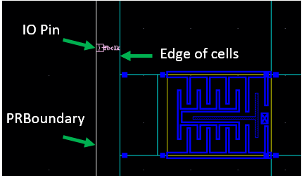
17.1 Design and Core Boundary Definitions
In Innovus, the design boundary or the IO Box is the actual design boundary. In contrast, the core boundary or the Core Box is where core rows are created and standard cells normally placed. Typically, for a digital block that has its floorplan implemented in Innovus, the IO Box and Core Box will be different in size. For example, the following command in Innovus creates a Core Box of width 18 and height 16.53 with a margin of 1 from the left and right edges of the Core Box to the left and right, respectively of the IO Box and a margin of 0.95 from the bottom and top edges of the Core Box to the bottom and top of the IO Box.
floorPlan -site CoreSite -s {20.0 18.43 1.0 0.95 1.0 0.95} -flip s
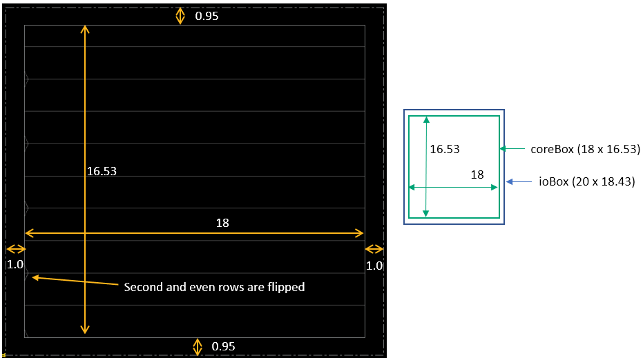
Within the Innovus database, the design boundary and core boundary are floorplan properties – database objects named as ioBox and coreBox. You can either measure the size of ioBox and coreBox in the layout window or use the dbGet command to query the x and y coordinates of the ioBox and coreBox.
> dbGet top.fPlan.ioBox
{0.0 0.0 20.0 18.43}
> dbGet top.fPlan.coreBox
{1.0 0.95 19.0 17.48}
If the above cell view is saved and loaded into Virtuoso, SKILL code can be run in the Command Interface Window (CIW) to query the box properties.
For example, when the following is entered in CIW,
cv=geGetEditCellView()
cv~>prBoundary~>bBox
the system should return:
((0.0 0.0)
(20.0 18.43)
)
Enter the following in CIW:
cv~>prBoundary~>ioBox
The system should return:
((0.0 0.0)
(20.0 18.43)
)
cv~>prBoundary~>coreBoxSpec
(((1.0 0.95)
(19.0 17.48)
) nil 0.0 "evenRowSpacingType" "oddRowFlipType"
db:0x2844419a
)
In Virtuoso, the PRBoundary object helps Innovus to determine the design boundary. For a design whose floorplan is created in Virtuoso (i.e. PRBoundary object is drawn in Virtuoso), the Core Box and IO Box have the same shape and size when queried in Innovus.
For example, assuming the same size of the PRBoundary object, when the following is entered in CIW,
cv=geGetEditCellView()
cv~>prBoundary~>bBox
the system returns
((0.0 0.0)
(20.0 18.43)
)
cv~>prBoundary~>ioBox
nil
cv~>prBoundary~>coreBoxSpec
nil
When running the following queries in Innovus, the same result is obtained for ioBox and coreBox objects.
> dbGet top.fPlan.ioBox
{0.0 0.0 20.0 18.43}
> dbGet top.fPlan.coreBox
{0.0 0.0 20.0 18.43}
The Core Box affects how the generated rows and routing tracks are physically located in the design. The details of how Innovus creates the rows and tracks will be described in detail in the next few sections.
17.2 Matching the Orientation of Rows and Standard Cells
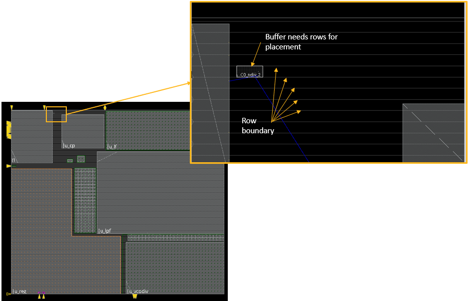
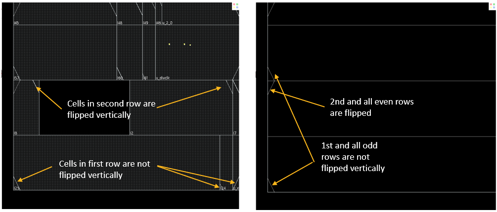
Consider a design that is initially implemented in Virtuoso and has no rows. When this cell view is loaded into Innovus, Innovus will automatically add rows to it. By default, the rows added by Innovus have the first and subsequent odd rows flipped vertically. Rows are created by Innovus for placement-type applications, such as buffer insertion for making an ECO change.
The above design is mainly a top-level design with only macros. In such designs, it does not matter whether the first or second row is flipped. However, for a design filled with only standard cells but no rows created in Virtuoso, some additional steps may be needed in Innovus to ensure that the orientation of the rows created by Innovus matches the orientations of the standard cells.
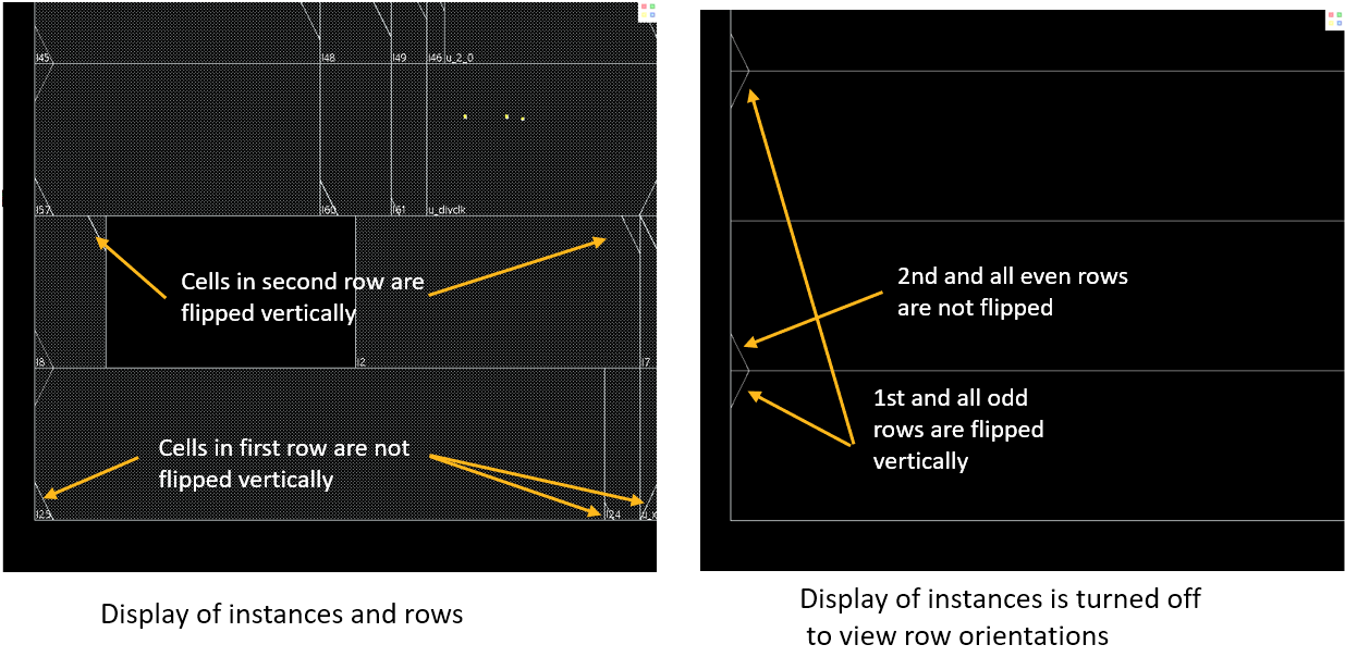
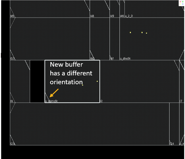
In the above case, the standard cells are manually placed in Virtuoso in a way that the cells of the first and subsequent odd rows are not vertically flipped while those in the second and subsequent even rows are vertically flipped. As by default, the first and other odd rows inserted by Innovus during init_design are vertically flipped, a row versus cell orientation issue arises. If at a later stage, a ECO change needs to be done to insert a buffer, this buffer will have a different orientation from the other cells in the same row.
Cell orientation issues can be detected by running the checkPlace command at the Innovus command prompt. Alternatively, you can use the Check Placement form, which can accessed from the Place menu. If routeDesign is run to perform routing, it will also call checkPlace before routing and generate violation markers where applicable.
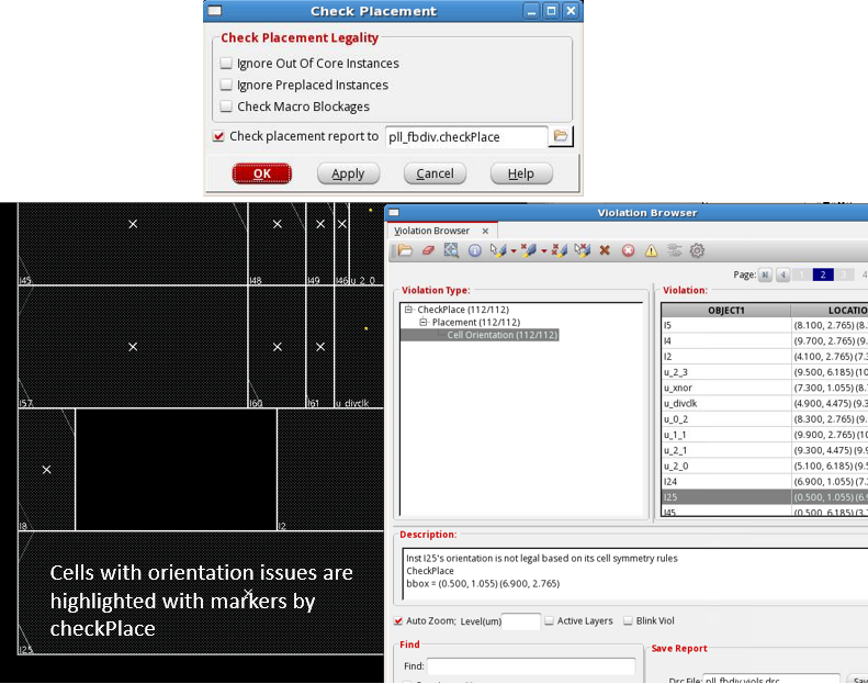
When cell orientation issues are detected, you can rectify the issue by switching the orientation of the cells using the steps mentioned in the "Switching the Orientation of the Standard Rows" section in the Placing Standard-cell-based Designs from Virtuoso chapter.
Another way to remedy the issue is as follows:
deleteRow -alldbGet selected.cell.site.nameLet us assume the systems returns:CoreSitedbGet top.fplan.coreBoxLet us assume the systems returns:{0 0 9.2 9.2}createRow -site CoreSite -area 0 0 9.2 9.2
17.3 Handling Gaps Between Standard Cells and the Design Boundary
17.3.1 Gap Between the Left Edge of the Leftmost Standard Cell and the Design Boundary
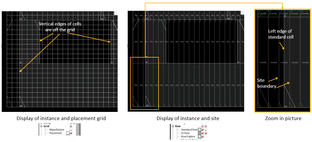
In the case shown below, not only do the manually placed standard cells have a different orientation from the rows created during init_design, there is also a gap between the left edge of the leftmost standard cell and the design boundary. However, having rows created with the correct orientation may not be enough if the cells are not snapping to the placement grid formed by the site width.
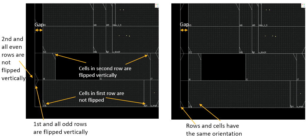
If checkPlace is run, the tool will report Cell Orientation and Off Placement Grid violations.
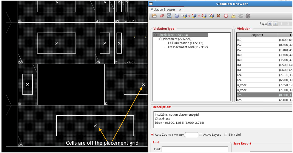
To understand what an Off Placement Grid violation means, select the Visibility check box of the Placement grid or Row Pattern option on the control panel in the main layout window. This will display the placement grid so that you can easily view whether a cell is placed on or off the grid.
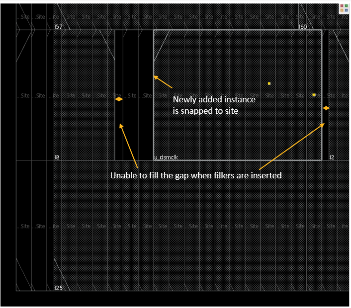
Such situations may cause issues at later stages of the implementation flow. For example, suppose a buffer is added by Innovus to make an ECO change. The inserted buffer will snap to the placement grid. In such a case, if you prompt Innovus to insert filler cells automatically to fill up the empty gaps in the design, Innovus will fail to fill up all the empty gaps because the gap between the new buffer and filler cells and other preexisting cells are not integral multiples of the site width.
To understand how the problem can be resolved, you must understand the spatial relationship between standard rows and the Core Box. The following diagrams explain how the left edge of the rows are determined by the tool. The -area option of the createRow command is used to specify the x and y coordinates of the lower-left and upper-right corners of the area to be filled with rows.
Assume that the x and y coordinates of the lower-left corner of the coreBox (and ioBox object) is 0,0 and the site width is 0.02. Now:
- If the
xcoordinate of the lower-left corner of the-areaoption is specified as0, the first site created will start its lower-left corner at0,0. - If the lower-left corner of the
-areaoption is specified as0.03, the first site created will have its lower-left corner located at0.04,0. Basically, the tool requires that the space between the Core Box and the left edge of the first site must be an integral multiple of the site width.
Thus, a standard cell placed with its lower-left corner at the point To fix the situation, one solution is to adjust the You may have to specify the 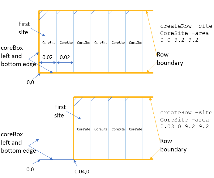
0.03,0 will be off the placement grid.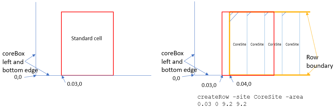
coreBox object using the changeFloorplan command. The diagrams below show that an adjustment of either 0.01 or 0.03 to move the left boundary edge of the coreBox will resolve the off-grid issue.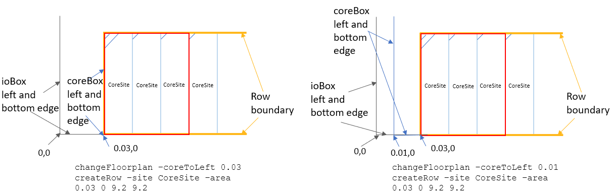
-noSnapToGrid option with changeFloorplan so that the tool will honor the actual value specified in the -coreToLeft option.
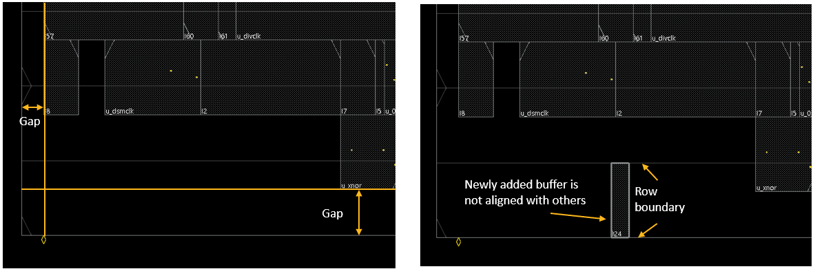
17.3.2 Gaps Between the Left and Bottom Edges of Standard Cells and the Design Boundary
In the following case, gaps are present between the left and bottom edges of the standard cells and the design boundary. A new instance inserted by Innovus will not be aligned with other cells in the same row because Innovus will snap the new instance to the row.
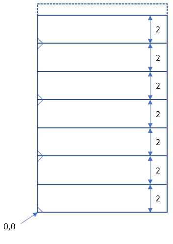
The following diagram explains how the bottom edge of the first row is determined by the createRow command. Let us assume the x and y coordinates of the lower-left corner of coreBox is 0,0, the row height is 2, and the site width is 0.02:
- If the
ycoordinate of the lower-left corner of the-areaoption is specified as0, the bottom edge of the first row will be located at 0. - If the
ycoordinate of the lower-left corner of the-areaoption is specified as0.4, the bottom edge of the first row will be located at2. The bottom edge of the first row will always snap to the location such that the distance between it and the bottom edge of the core box is an integral multiple of the row height.
Thus, a standard cell placed with its lower-left corner at the point If the vertical gap between the bottom edge of the standard cells and the bottom edge of In the above case, a cell view with a PRBoundary object of By running the The The0.03,0 will be off the placement grid.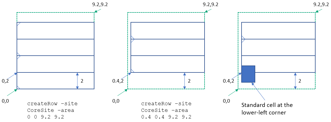
coreBox is not an integral multiple of the row height, the rows created will not fit with all the standard cells, irrespective of the value specified for the -area option. To make the rows fit, use the changeFloorplan command to readjust the coreBox before recreating the rows.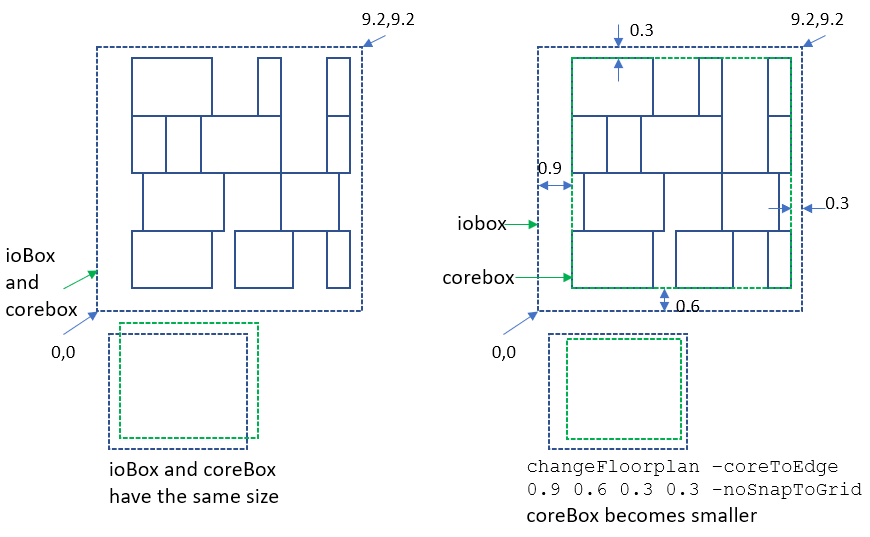
9.2x9.2 is loaded into Innovus.changeFloorplan command with the -coreToEdge option in Innovus, the size of the Core Box is adjusted such that the boundary of the Core Box aligns with the boundary of the box that virtually bounds all the standard cells. -coreToEdge option lets you specify the adjustment for the distances between the core box and io box on each side – left, bottom, right, and top. -noSnapToGrid option for changeFloorplan is needed so that the tool will honor the actual value specified in the -coreToEdge option. Without -noSnapToGrid, the tool may make slight adjustments to the specified values so that the Core Box is aligned with the existing tracks. However, as the existing tracks are not likely to be valid and need to be recreated in the next step, the alignment to tracks is not needed.
17.4 Creating Double-Height Rows
Suppose your design has double-height cells. Once the single-height rows created in Innovus are aligned with the cells, creation of double-height rows will be straightforward. The following diagram shows single-height rows with CoreSite as the site name and a site height of 2 populated in the design.
createRow -site CoreSite -area 0 0 9.2 20
Assume these single height rows are for cells with a ground pin (e.g. VSS) at the bottom and a power pin (e.g. VDD) at the top. If double-height cells with VSS-VDD-VSS combination of P/G pins are used in the design, run the following command to create the corresponding standard cell rows.
createRow -site CoreSiteDouble -area 0 0 9.2 20
The first y coordinate for the -area option will be 0 so that the first double-height row starts from the origin.
If double-height cells with VDD-VSS-VDD combination of P/G pins are used in the design, run the following command to create the corresponding standard cell rows. The first 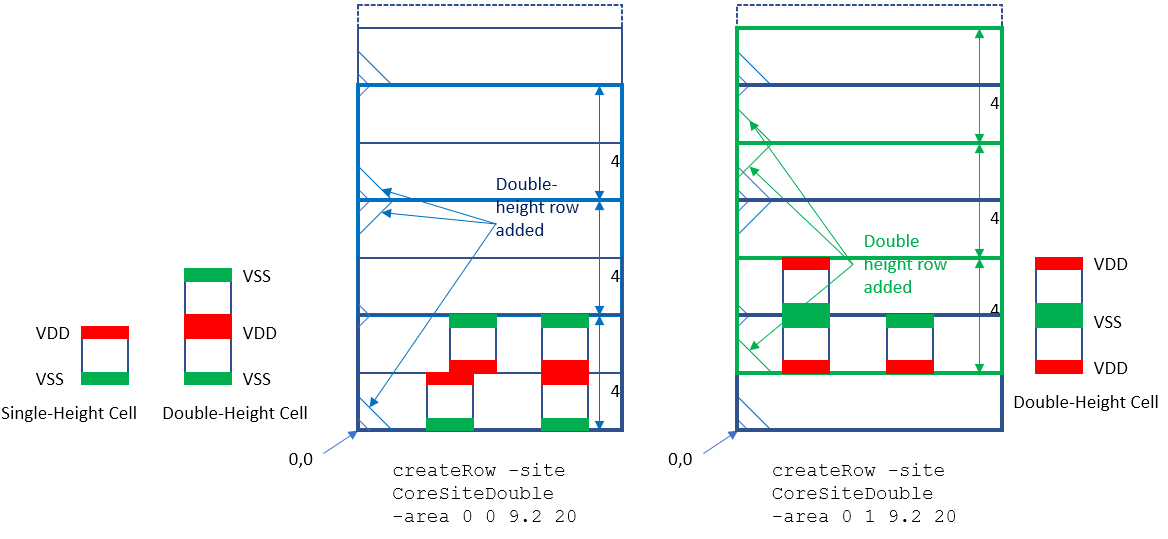
createRow -site CoreSiteDouble -area 0 1 9.2 20y coordinate for the -area option can be any value greater than 0 and less or equal to 2 so that the first double-height row starts from the bottom edge of the second single-height row.
17.5 Creating Routing Tracks with Respect to coreBox
The location of the lower-left corner of the Core Box affects not only row creation but also track creation.
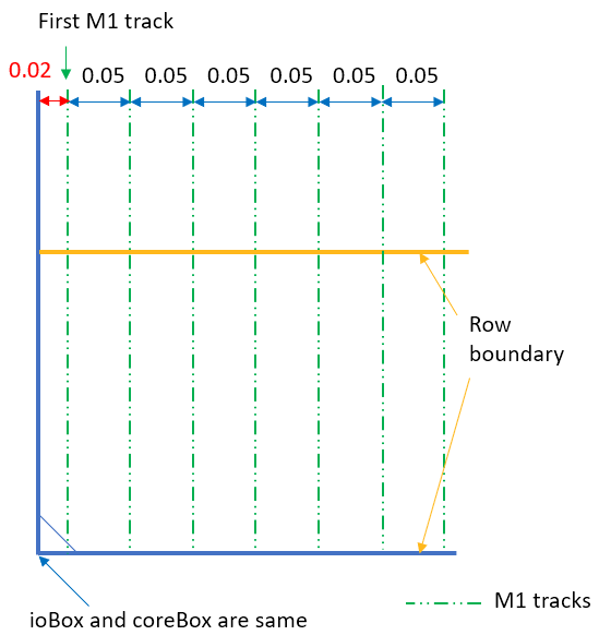
In the following diagram, the routing tracks are created with an offset of 0.02 um and a pitch of 0.05 um. The offset is measured from the left, vertical edge of the coreBox object to the first track. The initial rows and routing tracks are created by Innovus when the cell view is loaded (for example, with init_design).
By default, the tool automatically calculates the offset and pitch values for best pin access results. It does the computation by examining the pin locations of all standard cells (abstracts) stored in the Innovus database. However, the offset value it determines is measured from the boundary of the standard cell. Note that typically, the technology TLEF or the MSOA PDK have recommended values for the offset and pitch values of the routing tracks for each metal routing layers. These offset values are also typically measured from the boundary of the standard cell.
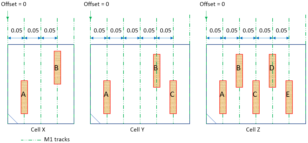
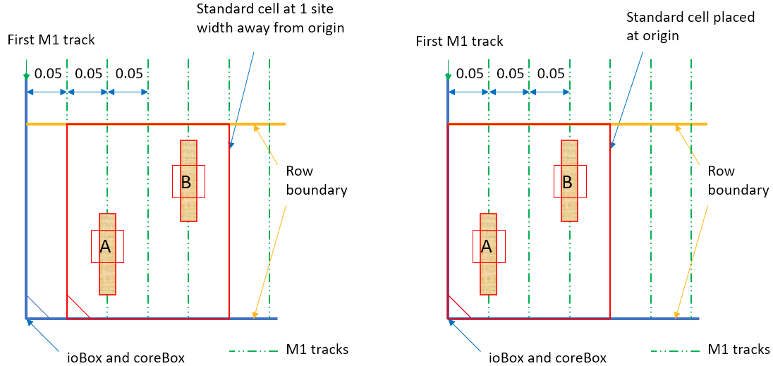
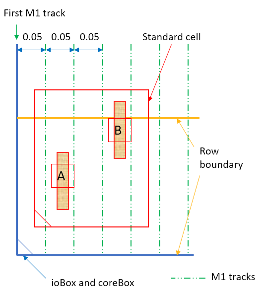
Assume that the standard cell being placed has a site width of 0.05 and the calculated offset and pitch are 0 and 0.05 um, respectively. If the cell is placed in a way that it is aligned with the placement grid (formed by the site width), then the calculated offset and pitch value will result in the tracks being aligned with the I/O pins of the standard cell. The two examples below show standard cells being placed on the grid, resulting in their I/O pins aligning with the tracks.
However, it is possible that the cells manually placed in Virtuoso are not aligned with the rows initially created by Innovus as shown in the beginning of this section. As a result, the tracks are not aligned with the centerline of the pins, which becomes a potential problem for routing.
To address such problems, follow the steps below to readjust the coreBox and recreate the tracks:
changeFloorplan -coreToEdge 0.03 0.06 0 0 -noSnapToGrid
add_tracks
Note that in some complex cases using multiple sets of standard cell libraries, you may have to specify the offset, pitch value, and the mask pattern. For example:
add_tracks -offsets {M1 vert 0 M2 horiz 0.04 M2 0 ...} -mask_pattern {M1 1 2 M2 1 2 ...}
17.6 Resizing the PRBoundary Object in Virtuoso
The problem mentioned in the previous section may also be resolved by opening the cell view in Virtuoso and resizing the PRBoundary object so that the left and bottom edges of the PRboundary object are aligned with the left and bottom edges of the bounding box for all the standard cells.
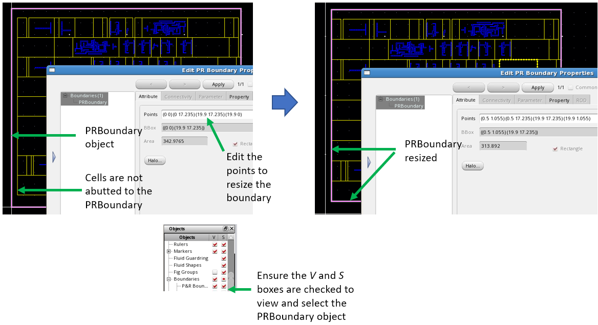
However, note that the above correction is not allowed in cases where gaps are preferred to enable the I/O pins and the standard cell edges to be spaced apart.