6.1 Overview
In the Cadence mixed signal implementation flow, Innovus Implementation System is used for complete implementation of digital content of the design. Very often the digital content is captured in one or more digital blocks contained in an Analog-on-Top (AoT) design. As the AoT design style is most often used by Virtuoso-based mixed signal design teams, the team may be unfamiliar with Innovus and the flow used for implementing the digital portion of mixed signal designs. As a result, many mixed signal design teams rely on digital designers to help implement the required digital functionality in a mixed signal design.
The Virtuoso Digital Implementation (VDI) environment in Virtuoso enables users who do not have familiarity with digital design methodology to implement the required digital functionality easily. The VDI environment invokes Innovus from within Virtuoso and creates the necessary script to implement the needed digital functionality completely.
To use the VDI environment, your unix path needs to have both an Innovus and a Virtuoso executable specified. If you cannot see the pull down menu for Innovus from within Virtuoso, chances are that you either do not have the Innovus installation specified in your UNIX path settings or there is a problem with that installation.
Please note that this interface only works with Virtuoso 6.1.8 or later versions. Customers using Virtuoso 6.1.7 will not be able to take advantage of this capability.
Note: The VDI interface requires the following product option license in addition to the Innovus startup license specified by the user:
- Mixed Signal Option (INVS30).
This license is checked-out automatically when the VDI interface is launched.
6.2 Invoking the VDI Environment
You can use the VDI environment to create the necessary scripts required to fully implement a digital block. In the AoT flow, the top-level floorplanning is typically done in Virtuoso and the boundary and the pins for the digital block are fixed during this step.
Set the blockType property as digital for the digital block so that the pins are snapped during the Move command or the Virtuoso Pin Optimizer on the routing grid. This will help during the routing stage in Innovus.
Use the following steps to launch the VDI interface:
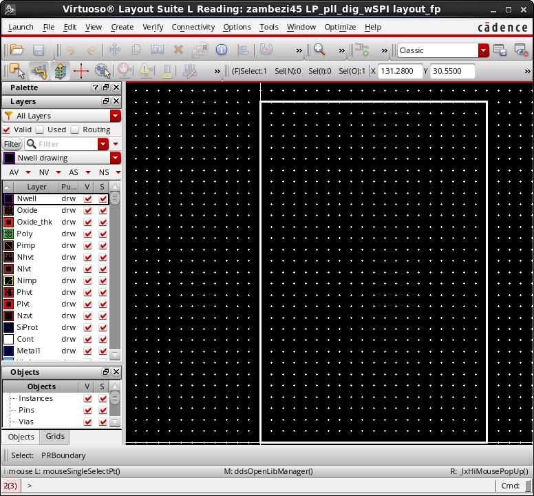
- Open the soft block representing the digital block as created during top-level floorplanning. At this point, the layout view of the digital soft block is just the boundary with the pins placed.
- Next, launch the Innovus plugin by selecting Plugins ->Innovus from the Launch menu of Virtuoso Layout Suite.
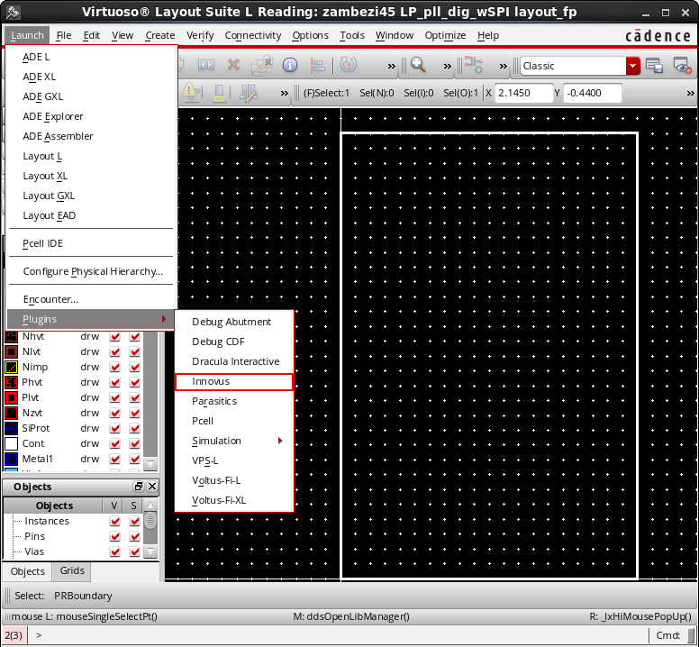
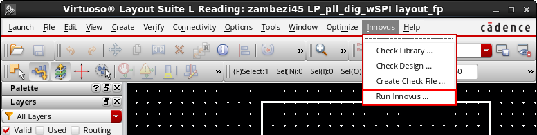
This adds the Innovus pull-down menu to the menu bar in the Virtuoso window. - The Innovus pull-down menu includes controls for the OpenAccess Database Interoperability Checker (oaDBChecker) as well as the VDI environment. To invoke the VDI environment, select Run Innovus from the pull-down menu.
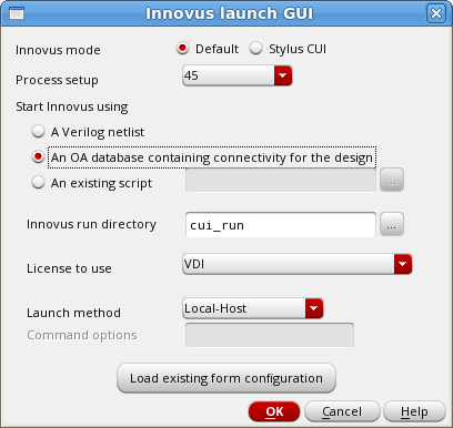
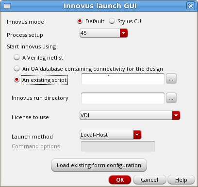
This opens the Innovus launch GUI form, which provides various options for launching Innovus in the VDI environment.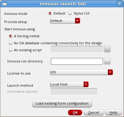
The table below describes these fields and options:
| Innovus mode |
Select the mode for creating the script and launching Innovus, Default or Stylus CUI. |
|
| Process setup | Select the process node, foundry, and the corresponding standard cell library from the drop-down list. The VDI environment will then populate the run scripts with the settings that are needed for that particular process setup. If the process setup used for your design is not listed, select Default from the list. | |
| Start Innovus using | Select the method to be used for starting Innovus through the VDI interface. The possible options are by using: | |
| A Verilog netlist | Select this option if you have been given a Verilog netlist that contains the connectivity for the digital block. See the Starting Innovus Using a Verilog Netlist section for subsequent steps. | |
| An OA database containing connectivity for the design |
Select this option if the connectivity for the digital block has been captured in a schematic, and a layout view containing the schematic connectivity has been created using Generate from Source (GFS) in Virtuoso. The VDI interface enables you to use the layout view containing the schematic connectivity to invoke Innovus. See the Starting Innovus Using an OpenAccess Database from Virtuoso section for subsequent steps. Note that Innovus is unable to read Virtuoso schematics directly. However, a layout view created in Virtuoso using GFS would contain the necessary connectivity for Innovus. |
|
| An existing script | Select this option if you have previously run the interface and saved the script. Specify the script name in the associated field to pass the script to the interface so that Innovus uses that script for the entire run. This option is useful in cases where you have made a manual modification to the script to either correct or improve the Innovus run, and do not need to go through the entire GUI to reconstruct the script. See the Starting Innovus Using an Existing Script section to view an example. | |
| Innovus run directory | Specify the directory in which the Innovus run files are to be created. If you leave this field blank (default), the run files are created in the current directory. | |
| License to use | Specify the license to be used. The VDI license is selected by default. | |
| Launch method |
Specify the xterm launch method. The available options are:
|
|
| Load existing form configuration | Select this option to load the form from a previously saved configuration file. The VDI flow includes a series of forms that help you capture the necessary information for the construction of the script. If you have previously run the interface, you can simply save the contents of the forms to a file and then load this file to fill in the forms with the data in the next run. See the Loading Existing Form Configuration section to view an example. | |
6.2.1 Starting Innovus Using a Verilog Netlist
If you select the A Verilog netlist option for starting Innovus from the Innovus Launch GUI form, the following form is displayed. You can specify the inputs required to run Innovus and implement the digital block for your Verilog netlist.
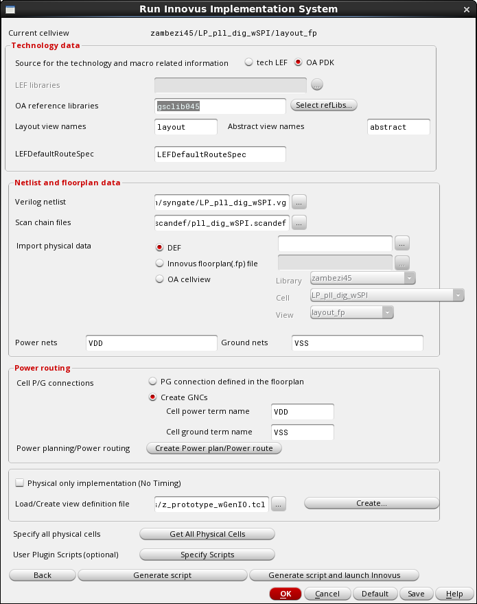
The table below describes the options in this form and how to complete them:
| Current cellview | Shows the cell view in Virtuoso from which the VDI interface was invoked. | |
| Technology data section | ||
| Source for the technology and macro related information |
Specify the source for the technology information. Choose one of the following options:
|
|
| LEF libraries |
Specify the LEF files to be used in this field if you are running the VDI interface in the LEF mode. Note that the first LEF file name should be of the technology LEF file. |
|
| OA reference libraries |
Specify the mixed signal OpenAccess reference libraries to be used for implementation in this field if you are running the VDI interface in the OpenAccess mode. Note that the first library in the list is the technology library for the particular process being used. This field is grayed out if you have selected the tech LEF mode for running the VDI interface. |
|
| Layout view names |
Specify the layout view names in this field if you are running the VDI interface in the OpenAccess mode. This field is grayed out if you have selected the tech LEF mode for running the VDI interface. |
|
| Abstract view names |
Specify the abstract view names in this field if you are running the VDI interface in the OpenAccess mode. This field is grayed out if you have selected the tech LEF mode for running the VDI interface. |
|
| LEFDefaultRouteSpec |
Specify the name of the Constraint Group in the MSOA PDK containing the technology information for Innovus. Typically, this specificaion is called LEFDefaultRouteSpec. However, if your MSOA PDK has a different name, specify that here. This field is grayed out if you have selected the tech LEF mode for running the VDI interface. |
|
| Netlist and floorplan data section | ||
| Verilog netlist |
Specify the path to the Verilog netlist containing the connectivity information for the digital block being implemented. |
|
| Scan chain files |
Specify the path to the scan file, if available, for scan chain insertion. |
|
| Import physical data |
Specify the file containing the floorplan for the digital block. If you invoked the VDI interface from a layout view in Virtuoso, the OA cellview field is automatically set to that lib/cell/view. Alternatively, you can use a DEF file or a Innovus floorplan file as the block floorplan. The DEF and Innovus floorplan (.fp) file options are intended for use by LEF/DEF users of the VDI interface, but they can also be used by OpenAccess users, if needed. |
|
| Power nets |
Specify all the power nets in the design here. |
|
| Ground nets | Specify all the ground nets in the design here. | |
| Power routing section | ||
| Cell P/G connections | Specify the power/ground (P/G) connections here. Choose one of the following options:
|
|
| Power planning/Power routing → Create Power plan/Power route | Click this button to create power stripes and routes through the GUI for the digital block being implemented. This is required if the floorplan you loaded for the digital block does not already have power stripes and power routing configured. See the Power Planning/Power Routing section for more details on creating power stripes and power routing through the GUI. | |
| Physical only implementation (No Timing) | Select this check box if you want a physical-only implementation. In the physical-only implementation mode, timing analysis or timing optimization is not done. This mode is ideal for small digital blocks that do not have critical timing paths. This mode is default and is also invoked if you do not specify a view definition file in the Load/Create view definition file field. | |
| Load/Create view definition file | Specifies the view definition file required for running Innovus. The view definition file describes the modes and corner the analysis engine in Innovus should use when evaluating timing. The VDI interface supports the following implementation modes:
For all three implementation modes, you must specify a view definition file.
If you already have the view definition file, you can specify its path in the Load/Create view definition file field to load it. Alternatively, click the Create button to create a new view definition file. See the Creating the View Definition File section for more details. Note - If you want a physical-only implementation for the block, select the Physical only implementation (No Timing) check box and leave the Load/Create view definition file field blank. |
|
| Specify all physical cells → Get All Physical Cells | Click the Get All Physical Cells button to extract the list of all physical cells (TIE, PAD FILLER, WELLTAP, ENDCAP, and CORE FILLER cells) from the specified OpenAccess reference libraries or LEF files. See the Specifying Physical Cells section for more details. | |
| User Plugin Scripts (optional) → Specify Scripts | Click the Specify Scripts button if you want to plug in your own code in the Innovus script. This opens the Plugin form, which provides options for adding plugin files at various stages in the Innovus script. See the Specifying Optional Plugin Scripts section for more details. | |
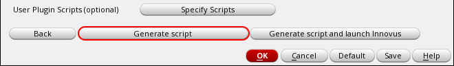
| Generate script | Click this button after completing all settings in the form to invoke the script generation part of the interface. The generated script is displayed in a vi text editor window, allowing you to customize it, if required. The script contains all the necessary steps required to implement a design using Innovus, based on the inputs you have specified.
See the Generating the Innovus Script section for more details. |
|
| Generate script and launch Innovus | Click this button to generate the script and launch Innovus in a single step. Use this button if you do not need to customize the script generated by the VDI interface in any way. See the Generating the Innovus Script section for more details. | |
6.2.2 Starting Innovus Using an OpenAccess Database from Virtuoso
Instead of using a Verilog netlist, the VDI interface could also get the connectivity information for the digital block from an OpenAccess database that has been properly created, using Virtuoso XL connectivity driven flow. The logical connectivity of the design should have been captured using a schematic in Virtuoso-XL, and a layout database should have been created using Generate From Source (GFS). In such a case, you should select the An OA database containing connectivity for the design option from the Innovus Launch GUI form:
Note - This is the only way Innovus can implement a digital block that does not have connectivity captured in a Verilog netlist. A workaround is to generate a Verilog netlist from a schematic in Virtuoso, and then use the VDI interface with the generated Verilog netlist. However, the generation of the Verilog netlist in Virtuoso has to be controlled using special settings to make the generated Verilog netlist consumable by Innovus.
When you click OK after selecting An OA database containing connectivity for the design option, the following form is displayed:
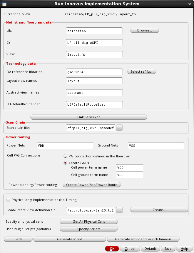
The Run Innovus Implementation form guides you through the process of starting Innovus using an OpenAccess database for connectivity. Notice that the the netlist is populated with the cell view in Virtuoso from which the VDI interface was invoked.
Most options in this form are the same as described in the Starting Innovus Using a Verilog Netlist section. Refer to this section for details of setting these options.
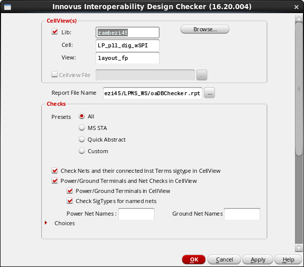
An addition to the Run Innovus Implementation form when you start Innovus using an OpenAccess database is the OADBChecker button. As you are using an OpenAccess database of the cell view to drive Innovus, you should run the interoperability checker to determine the readiness of the design and the technology library for use by Innovus. Clicking the OADBChecker button launches the Innovus Interoperability Design Checker form. For details on how to use this form, see the OpenAccess Database Interoperability Checker chapter.
6.2.3 Starting Innovus Using an Existing Script
If you have previously run the VDI interface and saved the script, you can start Innovus by choosing the An existing script option from the Innovus Launch GUI form:
Specify the script name in the associated field to pass the script to the interface so that Innovus uses that script for the entire run. The VDI interface will skip the entire GUI sequence for capturing your inputs and will instead launch Innovus and implement the digital block based on the settings in the specified script. This option is useful in cases where you have made a manual modification to the script to either correct or improve the Innovus run.
6.2.4 Loading Existing Form Configuration
The VDI flow includes a series of forms that help you save the necessary information for the construction of the script. If you have previously run the interface, you could simply recall the data entered in the forms when you next run the VDI flow. Click the Load existing form configuration button in the Innovus Launch GUI form, and select the file in which you have saved the form configuration in the Load Form Values to file form.
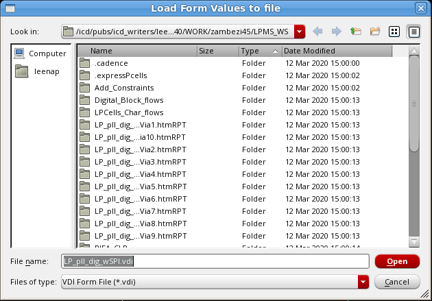
The VDI interface prefills all the forms and subforms in the sequence with the settings captured in the form value file that you loaded. For example, the Run Innovus Implementation System form below has been prefilled with the values captured from a previous run.
6.3 Configuring Power Planning and Power Routing
You can use the Power Planning form to configure how power routing is done for the digital block being implemented. To access the Power Planning form, click the Create Power plan/Power route button in the Power routing section of the Run Innovus Implementation System form.
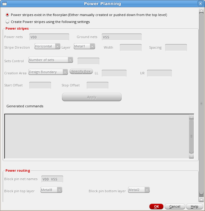
The table below describes the options in this form and how to configure them:
| Power stripes exist in the floorplan |
Select this option if power stripes and power routing already exist in the floorplan for the digital block. The power stripes could have been either manually created or pushed down from the top-level floorplan. If the Power stripes exist in the floorplan option is selected, the rest of the form is grayed out. However, if the floorplan has only the power stripes but the connections to corePins and blockPins need to be created, uncomment the |
|
| Create Power stripes using the following settings |
Create power stripes and power routing based on the settings you specify in the Power stripes and Power routing sections of the form. The VDI interface generates the necessary entries in the Innovus script based on the values you specify. |
|
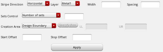
| Power stripes | Specify the settings for the power stripes in this section as described below. | |
|
Power nets Ground nets |
Specify the power and ground nets in these fields.
The interface auto-fills the power and ground net names that have been specified in the main GUI. |
|
| Stripe Direction | Select the stripe direction here and then specify the layer, width, spacing, and other settings for the stripe set. After clicking Apply, you can select another stripe direction and specify settings for that direction.
|
|
|
Layer |
Select the layer for the power and ground nets from the drop down field. The layer names are automatically filtered in the drop-down list, based on the direction set in the technology data.
|
|
|
Width |
Specify the width of the stripes for each direction. You can specify a different width for each net within a set. You can specify different widths for different layers. Make sure that you specify reasonable spacing and width values in the GUI. If, for example, you use a width value that is smaller than the minimum width value for that particular layer, Innovus will throw Warning or Error messages when the script is run. If this happens, you can modify the values in the Innovus scripts based on the recommendation in the log file or the LEFDefaultRouteSpec Constraint Group values. |
|
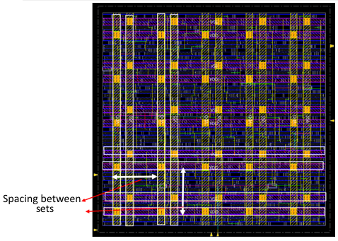
| Spacing | Specifies the spacing between stripes in each set. You can specify different spacing between each pair of stripes.
|
|
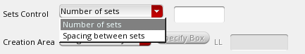
| Sets Control | Use this drop-down to control how many stripe sets are created:
|
|
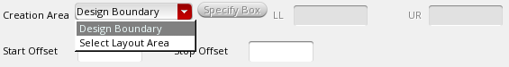
| Creation Area | Specify the area in which the stripes are to be created. By default, the stripe sets are created within the entire design boundary. If you want to create stripes within a specific area, choose Select Layout Area from the Creation Area drop-down list, click the Specify Box button, and draw a box in the layout cellview for the required area. The lower-left and upper-right coordinates of the box are populated in the LL and UR fields, respectively.
|
|
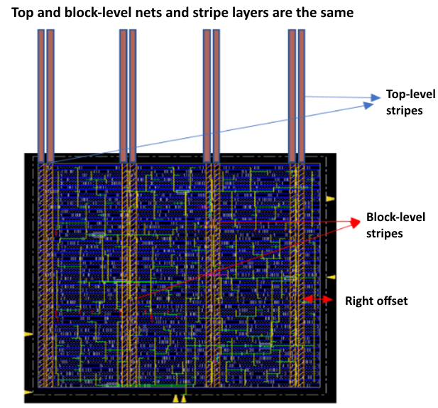
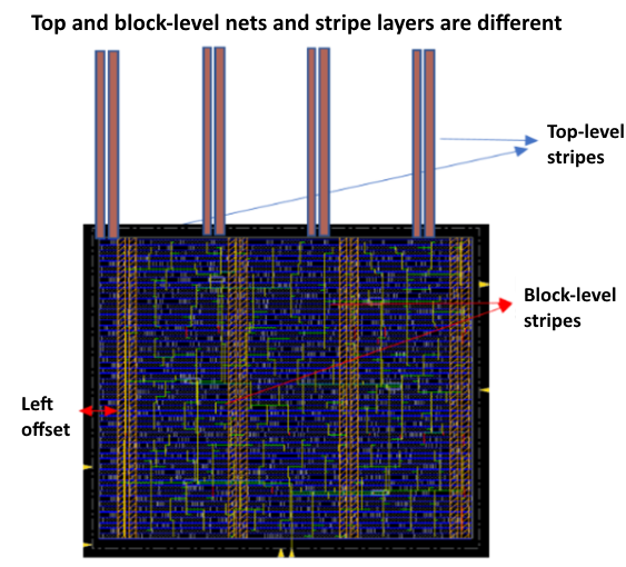
| Start Offset | Specify the starting offset value from the appropriate boundary of the stripe generation area to the nearest edge of the first stripe. In some designs, the top-level stripe may break at the block boundary. In this case, make sure that the stripe generated in the block aligns with the top-level stripe by using the Start Offset option, which is based on the If the P/G nets are on the same layer inside the block as they are at the top level, you can use the Start Offset option to ensure that the stripes are continuous. Also, make sure that the global connectivity of the top-level and the block level nets match.
If the net names of the top and bottom are different, use the
Note that for vertical stripes, the offset is measured from the left side of the stripe generation area to the left edge of the first stripe in the Refer to latest Innovus Text Command Reference for details on using the |
|
| Stop Offset | Specify the stopping offset value off the appropriate boundary of the stripe generation area. This option is based on the |
|
| Apply | Click this button to create the |
|
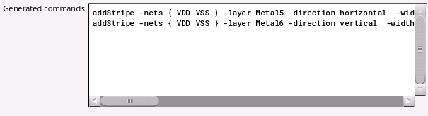
Generated commands |
This section displays all the
You can review, edit, and delete commands from this section. The final commands in this section are added to the Innovus script generated by the VDI interface. |
|
| Power routing |
Specify the settings for the power routes in this section as described below. |
|
| Block pin net names | Specify the net names of the block pins to be connected by the power routing engine, Special Route (Sroute), in this field. You can specify multiple net names separated by a space as shown below.
The interface auto-fills the power and ground net names that have been specified in the main GUI. |
|
|
Block pin top layer Block pin bottom layer |
Specify the top and bottom layer to be used in routing. If you leave these fields blank, Sroute will try to route all power/ground pin layers of block pins to the closest power/ground stripe.
|
|
Note: If the digital block has only standard cells and no blocks in the floorplan, the power routing section can be ignored. Innovus, by default, will only route the standard cell pins (followpins). Based on the values you specify in the Power routing section of the form, the VDI interface generates commands, such as the following, in the Innovus script:
|
||


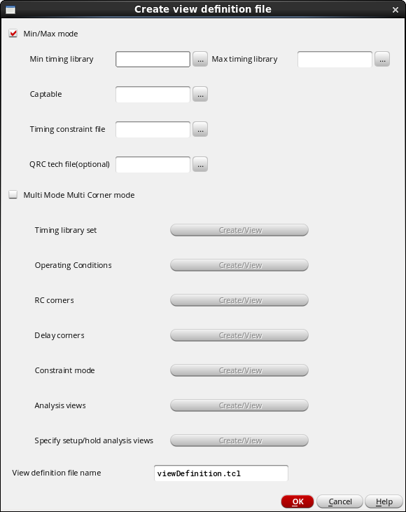
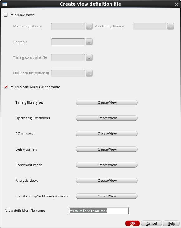
The view definition file is required by Innovus to complete many of the steps in physical implementation of a particular block. It describes the modes and corner the analysis engine in Innovus should use when evaluating timing. In its simplest form, the view definition file could just define the clock in the design. In a more complex form, it could define multiple mode and corners for the physical implementation flow. To see an example of a view definition file, click here. The VDI interface supports the following modes for the physical implementation of a digital block: The mode you choose for implementing the digital block is controlled through a view definition file. To create a view definition file from the VDI interface, click the Create button next to the Load/Create view definition file field in the Run Innovus Implementation System form: This opens the Create view definition file form:
In the single timing analysis mode, Innovus uses a single set of delays using one library group. To invoke this mode, choose the Min/Max mode in the Create view definition file form of the VDI interface, but specify only one timing library (either Min timing library or Max timing library) instead of two libraries as shown below: In addition to the path to a Min timing library (or a Max timing library), you can specify the following options in the Create view definition file form while implementing a digital block in the single timing analysis mode: Specify the capacitance table to be used in the implementation in this field. The capacitance table and the QRC tech file are used in the parasitic extraction portion of the implementation flow. If only one of the files is available, you could specify just a single file. If only the capacitance table file is provided, the parasitic extraction step in the flow will run in effort level
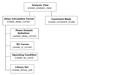
In the Best case/Worst case (BcWc or Min/Max) analysis mode, Innovus uses two set of delays, one from the maximum library group and the other from the minimum library group, in a timing analysis run. To invoke this mode, choose the Min/Max mode in the Create view definition file form of the VDI interface, and specify both minimum and maximum timing libraries as shown below: In addition to specifying paths to both Min timing library and Max timing library, you can specify the following options in the Create view definition file form while implementing a digital block in the BcWc or Min/Max analysis mode: Specify the capacitance table to be used in the implementation in this field. The capacitance table and the QRC tech file are used in the parasitic extraction portion of the implementation flow. If only one of the files is available, you could specify just a single file. If only the capacitance table file is provided, the parasitic extraction step in the flow will run in effort level In the full multi-mode multi-corner (MMMC) analysis mode, Innovus uses a tiered approach to assemble the information necessary for timing analysis and optimization. Each top-level definition is called an analysis view. The diagram below depicts the various elements required for creation of analysis views. Each analysis view is composed of a delay calculation corner and a constraint mode: The VDI interface guides you through the creation of all required entries in the view definition file for an MMMC implementation. Once all analysis views are created using the interface, you can select the active analysis views to be used for representing different variations that will be analyzed during the implementation of the digital block. Note - In the first version of the VDI interface, the script generation supported one power domain. As such, power domain definitions are not needed for creating the view definition file, as shown in the diagram. To invoke the multi-mode multi-corner (MMMC) analysis mode, select the Multi Mode Multi Corner mode option in the Create view definition file form of the VDI interface. When you do so, the options for creating or viewing timing library sets, operating conditions, RC corners, delay corners, constraint mode, and analysis views are enabled as shown below: The following sections describe the procedure for creating or viewing timing libary sets, operating conditions, RC corners, delay corners, constraint modes, and analysis views: You can specify a name for the view definition file you are creating in the View definition file name field. The default name is
Timing library sets are the basic elements of a view definition file. Typical designs contain standard cells, memories, IPs, pads, and so on. Library sets allow a group of library files to be treated as a single entity so that higher-level descriptions, such as delay corners, can simply refer to the library configuration by name. A library set may contain only timing libraries or may also include To complete creating timing library sets: Whenever required, you can view any of the library set you have created by selecting its name from the Name drop-down list in the Add library set form. Note - The order in which you define timing libraries is important. The software considers the first library you specify in the list as the master library, with each successive library having a lower priority.
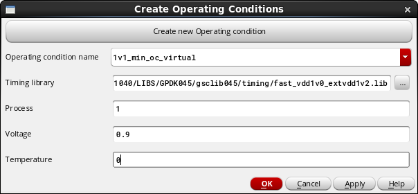
In digital designs, there are situations when there are no predefined operating conditions in the timing libraries being used for implementing the design, or the pre-existing operating conditions in the timing libraries are not consistent with the operating environment of the design. In these cases, it is important to specify the desired operating conditions, so Innovus could use the data to derate the data in the timing libraries as well as perform other aspects of analysis. Instead of actually modifying the timing libraries to add or adjust operating condition definitions, you can create a set of virtual operating conditions for a library, to define a process, voltage, and temperature (PVT) operating point. As far as Innovus is concerned, it would see these 'virtual' operating conditions, as if they actually existed in the timing library. To create operating conditions, click the Create/View button next to Operating conditions in the Create view definition file form of the VDI interface. This launches the Create Operating Conditions form. To complete creating operating conditions: Whenever required, you can view any of the operating conditions you have created by selecting its name from the Operating condition name drop-down list in the Create Operating Conditions form.
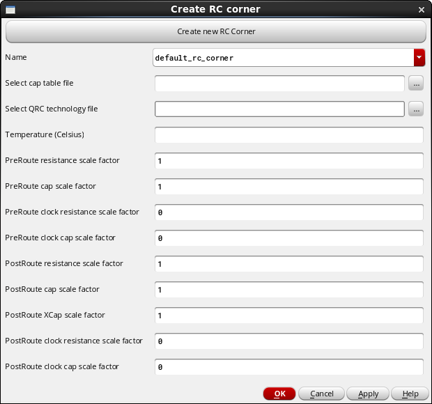
An RC corner provides Innovus all the information it needs to properly extract the required parasitic information for implementing the digital design. RC corners are also used for sign-off extraction after the design is fully implemented. Innovus extracts and stores a unique set of parasitics for each RC corner that you identify as an active corner. Note that you can choose which of the RC corners you create are active. The RC corners that are not identified as active are not used in analysis. To create RC corners, click the Create/View button next to RC corners in the Create view definition file form of the VDI interface. This launches the Create RC corner form: As can be seen in the form, different derating factors can be used in the creation of the RC corner. If no derating of the RC data is desired, you can simply provide the capacitance table and the Quantus QRC technology file, and leave all other fields to default.
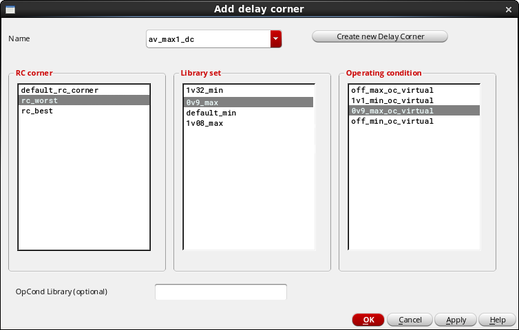
You can create the delay calculation corner to be used by Innovus after you have completed creating the timing library sets, operating conditions, and RC corners. In addition to library sets, operating conditions, and RC corners, a delay calculation corner can also include power domain definitions. However, as mentioned earlier, this version of the VDI interface creates Innovus scripts only for designs with a single power domain. Therefore, you do not need to create power domain definition at present for creating a delay corner. To create delay corners, click the Create/View button next to Delay corners in the Create view definition file form of the VDI interface. This launches the Add delay corner form: To create delay corners:
A constraint mode defines one of the many possible modes of operation of a design. For example, when implementing the digital block using the VDI interface, you may be interested in analyzing the timing of the block in the functional and test modes. For designs with multiple power domains, another possible mode of operation is Dynamic Voltage and Frequency Scaling (DVFS). To get the most accurate analysis results, different timing constraint (SDC) files are used for the different modes in which the digital block will function. A constraint mode consists of a list of SDC files that contain timing analysis information, such as the clock specifications, case analysis constraints, I/O timings, and path exceptions that make each mode unique. As an example, the test mode of the digital block will have To create constraint modes, click the Create/View button next to Constraint mode in the Create view definition file form of the VDI interface. This launches the Create constraint mode form: To create constraint modes:
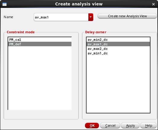
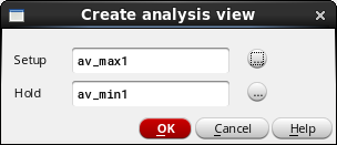
An analysis view is a combination of a delay calculation mode and a constraint mode. The analysis view is the object that actually controls the multi-mode multi-corner (MMMC) analysis that takes place in Innovus. To create analysis views, click the Create/View button next to Analysis views in the Create view definition file form of the VDI interface. This launches the Create analysis view form: Now, simply select the constraint mode/delay corner combination, specify a name, and click on the Apply button.
In this stage of creating an MMMC view definition file, the analysis views created in the previous step can be used to specify which of the analysis views created in the previous step can be used by the analysis engine during setup and hold analysis. To specify setup/hold analysis views, click the Create/View button next to Specify setup/hold analysis views in the Create view definition file form of the VDI interface. This launches the Create analysis view form: Click the ... button next to the Setup and Hold fields to select the desired views from the list of available analysis views.6.4 Creating the View Definition File

6.4.1 Implementing a Digital Block in the Single Timing Analysis Mode
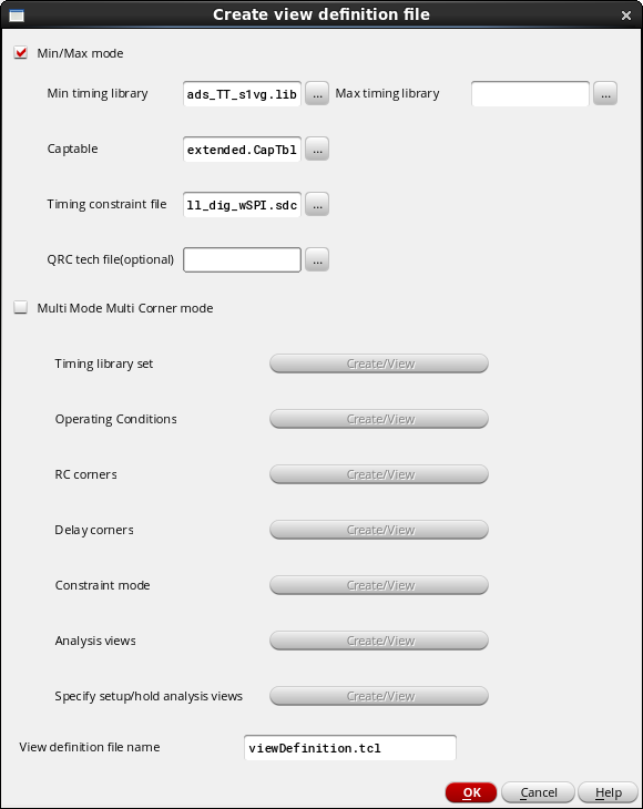
Min/Max mode
Captable
Low.Timing constraint file
Specify the required timing constraint file here. The timing constraint file (.sdc) is created during the logic synthesis part of the implementing the digital block.
QRC tech file (optional)
Specify the name of the Quantus QRC Technology file here. If the QRC tech file is provided, the parasitic extraction will use effort level
High for a more accurate extraction.View definition file name
Specify a name for the view definition file you are creating here. The default name is
viewDefinition.tcl.6.4.2 Implementing a Digital Block in the BcWc or Min/Max Analysis Mode
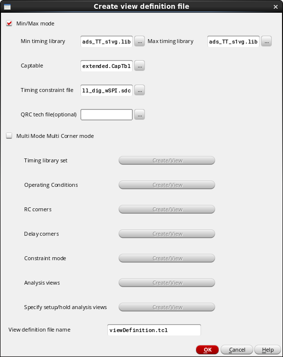
Min/Max mode
Captable
Low.Timing constraint file
Specify the required timing constraint file here. The timing constraint file (.sdc) is created during the logic synthesis part of the implementing the digital block.
QRC tech file (optional)
Specify the name of the Quantus QRC Technology file here. If the QRC tech file is provided, the parasitic extraction will use effort level
High for a more accurate extraction.View definition file name
Specify a name for the view definition file you are creating here. The default name is
viewDefinition.tcl.6.4.3 Implementing a Digital Block in the MMMC Analysis Mode
viewDefinition.tcl.6.4.3.1 Creating/viewing timing library sets
.cdb libraries for running signal Integrity. To create a timing library set, click the Create/View button next to Timing library set in the Create view definition file form of the VDI interface. This launches the Add library set form.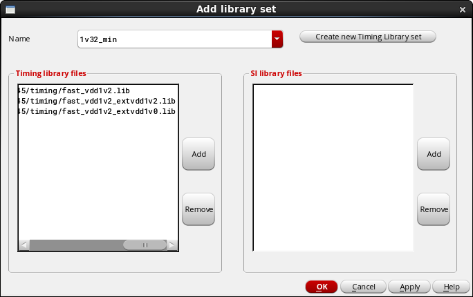
6.4.3.2 Creating/viewing operating conditions
6.4.3.3 Creating/viewing RC corners
6.4.3.4 Creating/viewing delay corners
6.4.3.5 Creating/viewing constraint modes
set_false_path for the paths that are not executed in this mode. Click here to view an example of a simple SDC file for a digital block.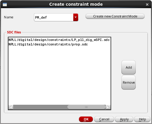
6.4.3.6 Creating/viewing analysis views
6.4.3.7 Specifying setup/hold analysis views
6.5 Specifying Physical Cells
To extract physical cells from the specified OpenAccess reference libraries or LEF files, click the Get All Physical Cells button on the Run Innovus Implementation System form. This opens the Physical Cells form, which you can use to extract the required physical cells (TIE, PAD FILLER, WELLTAP, ENDCAP, and CORE FILLER cells) from the specified OpenAccess reference libraries or LEF files.
Note - The extraction of the physical cells depends on the cellType being set properly in the LEF files or the OpenAccess reference libraries.
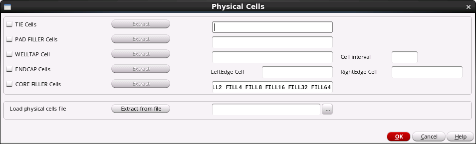
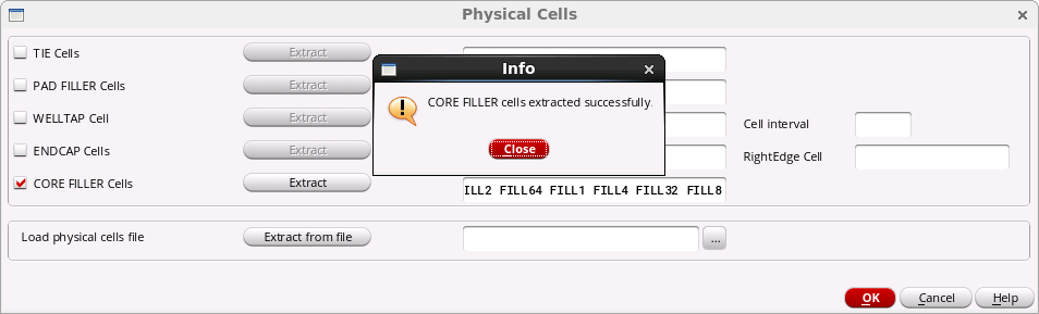
The Physical Cells form provides an Extract button for each physical cell type. To extract a specific type of physical cell, select the check box next to it and click the corresponding Extract button. The tool extracts the available physical cells of that type and displays them in an editable text box. You can update the list of cells, as required.
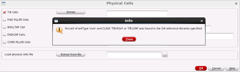
If physical cells of the selected type are not available in the specified OpenAccess reference libraries or LEF files, the VDI interface displays a message as shown below:
Instead of extracting each cell type individually, you can choose to load all physical cells from a specified file. To do so, select the browse button (...) corresponding to the Load physical cells file option in the new Physical Cells to select the file containing the cell names and then click the Extract from file button.
A typical physical cells file will have the following format:
Tie Cells: cell_a cell_b cell_c ...
CORE Filler Cells:cell_d cell_e cell_f ...
PAD Filler Cells: cell_g cell_h cell_i ...
LeftEndCap Cells: cell_j cell_k ...
RightEndCap Cells: cell_l cell_m
WellTap Cells: cell_n cell_o
Note - If you load the cells from a file, it will override all the cells extracted or specified previously. However, you can choose to load a file and then extract a particular physical cell type.
6.6 Specifying Optional Plugin Scripts
If you want to plug in your own code in the Innovus script, click the Specify Scripts button on the Run Innovus Implementation System form. This opens the Plugin form, which provides options for adding plugin files at various stages in the Innovus script as shown below:
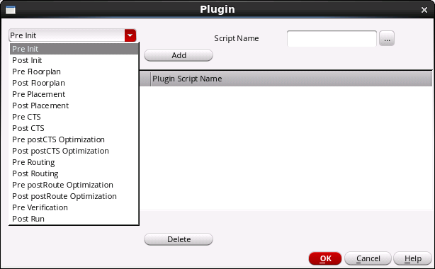
Select the required stage from the drop-down list, specify the path to the script in the Script Name field and click Add. Your script is plugged in at the specified stage into the Innovus script generated by the VDI interface.
6.7 Generating the Innovus Script
After you have made all the necessary settings in the Run Innovus Implementation System form, you need to invoke the script generation part of the VDI interface. You can choose to generate the script and customize it before launching Innovus or generate the script and launch Innovus in a single step.
6.7.1 With Customization
If you need to customize the script before launching Innovus, click the Generate script button.
The generated script is displayed in a vi text editor window, allowing you to customize it, if required. The script contains all the necessary steps required to implement a design using Innovus, based on the inputs you have specified. See the Generated Innovus Script Sample section to view an example of a generated Innovus script.
After making any necessary edits, save the script so that it can be reloaded, if required, for later runs. Next, click the OK button in the Run Innovus Implementation System form. This launches the Innovus executable in a separate window.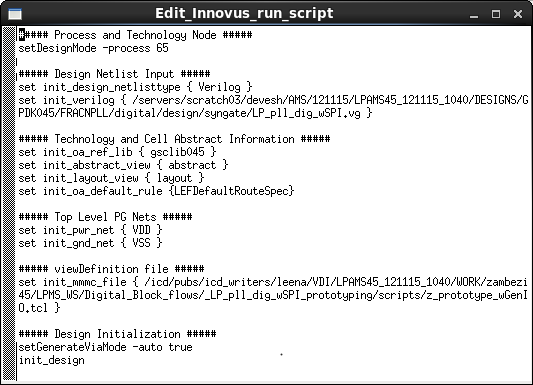
6.7.2 Without Customization
If you do not need to customize the script generated by the VDI interface in any way, you can generate the script and launch Innovus in a single step by clicking the Generate script and launch Innovus button instead.
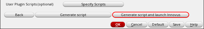
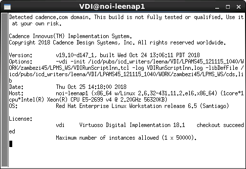
On clicking this button, the Run Innovus Implementation System form is closed automatically and the Innovus executable is launched in a separate window.
6.8 Completing the Implementation
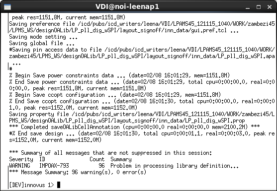
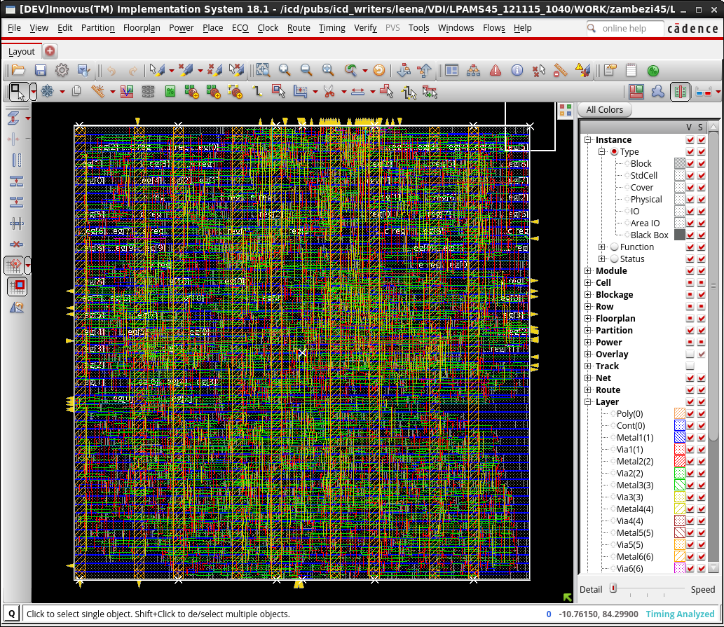
Innovus proceeds to run all the commands in the generated script. Once the complete script has been processed, the innovus> prompt is displayed.
Type win at the innovus > prompt to launch the Innovus GUI and view the fully implemented digital block:
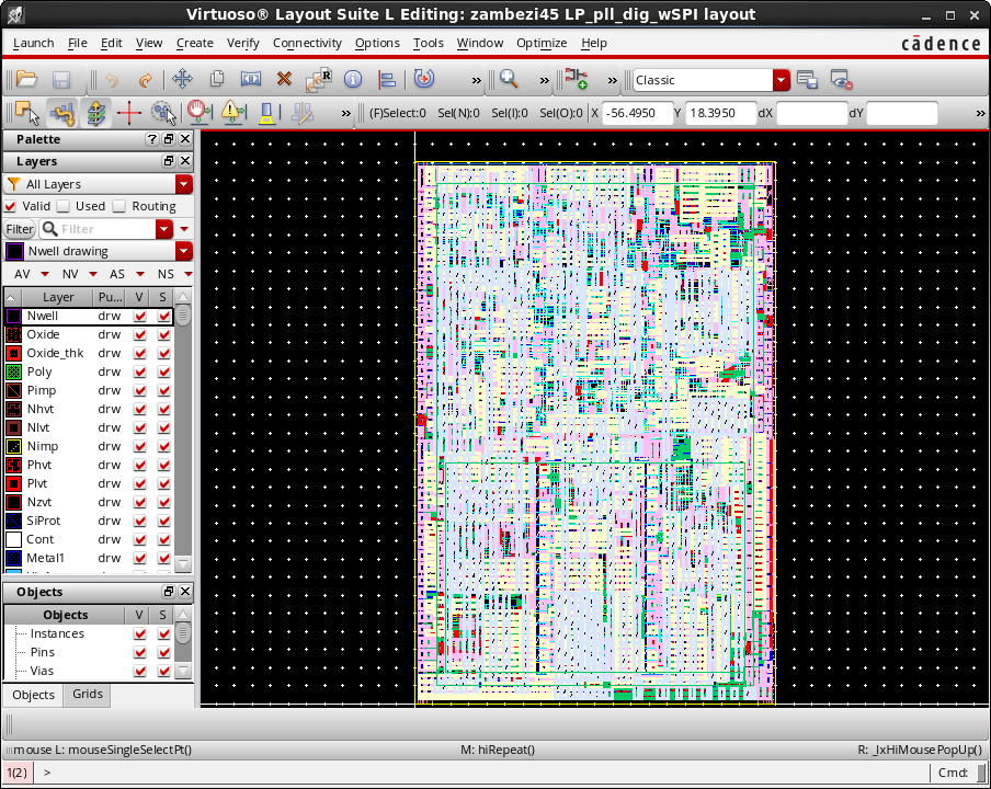
The implemented digital block can also be viewed in Virtuoso:
6.9 Sample Files
Here is an example of a view definition file:
6.9.1 Sample View Definition File
create_library_set -name 1v32_min\ -timing\ [list //LPAMS45_121115_1040/LIBS/GPDK045/gsclib045/timing/fast_vdd1v2.lib\ /LPAMS45_121115_1040/LIBS/GPDK045/gsclib045/timing/fast_vdd1v2_extvdd1v2.lib\ /LPAMS45_121115_1040/LIBS/GPDK045/gsclib045/timing/fast_vdd1v2_extvdd1v0.lib]create_library_set -name 1v1_min\ -timing\ [list /LPAMS45_121115_1040/LIBS/GPDK045/gsclib045/timing/fast_vdd1v0_extvdd1v2.lib\ /LPAMS45_121115_1040/LIBS/GPDK045/gsclib045/timing/fast_vdd1v0_extvdd1v0.lib\ /LPAMS45_121115_1040/LIBS/GPDK045/gsclib045/timing/fast_vdd1v0.lib]\ -si\ [list /LPAMS45_121115_1040/LIBS/GPDK045/gsclib045/celtic/fast.cdb]create_library_set -name 0v9_max\ -timing\ [list /LPAMS45_121115_1040/LIBS/GPDK045/gsclib045/timing/slow_vdd1v0_extvdd1v2.lib\ /LPAMS45_121115_1040/LIBS/GPDK045/gsclib045/timing/slow_vdd1v0_extvdd1v0.lib\ /LPAMS45_121115_1040/LIBS/GPDK045/gsclib045/timing/slow_vdd1v0.lib]\ -si\ [list /icd/hierflow/devesh/VDIFlow/LPAMS45_121115_1040/LIBS/GPDK045/gsclib045/celtic/slow.cdb]create_library_set -name 1v08_max\ -timing\ [list /LPAMS45_121115_1040/LIBS/GPDK045/gsclib045/timing/slow_vdd1v2.lib\ /LPAMS45_121115_1040/LIBS/GPDK045/gsclib045/timing/slow_vdd1v2_extvdd1v2.lib\ /LPAMS45_121115_1040/LIBS/GPDK045/gsclib045/timing/slow_vdd1v2_extvdd1v0.lib]create_op_cond -name off_max_oc_virtual -library_file //LPAMS45_121115_1040/LIBS/GPDK045/gsclib045/timing/slow_vdd1v0_extvdd1v2.lib -P 1 -V 0 -T 125create_op_cond -name 1v1_min_oc_virtual -library_file /LPAMS45_121115_1040/LIBS/GPDK045/gsclib045/timing/fast_vdd1v0_extvdd1v2.lib -P 1 -V 0.9 -T 0create_op_cond -name 0v9_max_oc_virtual -library_file /LPAMS45_121115_1040/LIBS/GPDK045/gsclib045/timing/slow_vdd1v0_extvdd1v2.lib -P 1 -V 0.9 -T 125create_op_cond -name off_min_oc_virtual -library_file /LPAMS45_121115_1040/LIBS/GPDK045/gsclib045/timing/fast_vdd1v0_extvdd1v2.lib -P 1 -V 0 -T 0create_rc_corner -name default_rc_corner\ -preRoute_res 1\ -postRoute_res 1\ -preRoute_cap 1\ -postRoute_cap 1\ -postRoute_xcap 1\ -preRoute_clkres 0\ -preRoute_clkcap 0create_rc_corner -name rc_best\ -cap_table /LPAMS45_121115_1040/TECH/GPDK045/gpdk045/soce/gpdk045.extended.CapTbl\ -preRoute_res 1\ -postRoute_res {1 1 1}\ -preRoute_cap 1\ -postRoute_cap {1 1 1}\ -postRoute_xcap {1 1 1}\ -preRoute_clkres 0\ -preRoute_clkcap 0\ -T 0\ -qx_tech_file /LPAMS45_121115_1040/LIBS/GPDK045/gsclib045/qrc/qx/gpdk045.tchcreate_rc_corner -name rc_worst\ -cap_table /LPAMS45_121115_1040/TECH/GPDK045/gpdk045/soce/gpdk045.extended.CapTbl\ -preRoute_res 1\ -postRoute_res {1 1 1}\ -preRoute_cap 1\ -postRoute_cap {1 1 1}\ -postRoute_xcap {1 1 1}\ -preRoute_clkres 0\ -preRoute_clkcap 0\ -T 125\ -qx_tech_file /LPAMS45_121115_1040/LIBS/GPDK045/gsclib045/qrc/qx/gpdk045.tchcreate_delay_corner -name av_max1_dc\ -library_set 0v9_max\ -opcond_library slow_vdd1v0_extvdd1v2\ -opcond 0v9_max_oc_virtual\ -rc_corner rc_worstupdate_delay_corner -name av_max1_dc -power_domain PD_def\ -library_set 0v9_max\ -opcond_library slow_vdd1v0_extvdd1v2\ -opcond 0v9_max_oc_virtualupdate_delay_corner -name av_max1_dc -power_domain PD_cal\ -library_set 0v9_max\ -opcond_library slow_vdd1v0_extvdd1v2\ -opcond off_max_oc_virtualcreate_delay_corner -name av_min2_dc\ -library_set 1v1_min\ -opcond_library fast_vdd1v0_extvdd1v2\ -opcond 1v1_min_oc_virtual\ -rc_corner rc_bestupdate_delay_corner -name av_min2_dc -power_domain PD_def\ -library_set 1v1_min\ -opcond_library fast_vdd1v0_extvdd1v2\ -opcond 1v1_min_oc_virtualupdate_delay_corner -name av_min2_dc -power_domain PD_cal\ -library_set 1v1_min\ -opcond_library fast_vdd1v0_extvdd1v2\ -opcond 1v1_min_oc_virtualcreate_delay_corner -name av_max2_dc\ -library_set 0v9_max\ -opcond_library slow_vdd1v0_extvdd1v2\ -opcond 0v9_max_oc_virtual\ -rc_corner rc_worstupdate_delay_corner -name av_max2_dc -power_domain PD_def\ -library_set 0v9_max\ -opcond_library slow_vdd1v0_extvdd1v2\ -opcond 0v9_max_oc_virtualupdate_delay_corner -name av_max2_dc -power_domain PD_cal\ -library_set 0v9_max\ -opcond_library slow_vdd1v0_extvdd1v2\ -opcond 0v9_max_oc_virtualupdate_delay_corner -name av_max2_dc -power_domain PD_cal\ -library_set 0v9_max\ -opcond_library slow_vdd1v0_extvdd1v2\ -opcond 0v9_max_oc_virtualcreate_delay_corner -name av_min1_dc\ -library_set 1v1_min\ -opcond_library fast_vdd1v0_extvdd1v2\ -opcond 1v1_min_oc_virtual\ -rc_corner rc_bestupdate_delay_corner -name av_min1_dc -power_domain PD_def\ -library_set 1v1_min\ -opcond_library fast_vdd1v0_extvdd1v2\ -opcond 1v1_min_oc_virtualupdate_delay_corner -name av_min1_dc -power_domain PD_cal\ -library_set 1v1_min\ -opcond_library fast_vdd1v0_extvdd1v2\ -opcond off_min_oc_virtualcreate_constraint_mode -name PM_def\ -sdc_files\ [list /LPAMS45_121115_1040/DESIGNS/GPDK045/FRACNPLL/digital/design/constraints/LP_pll_dig_wSPI.sdc\ /LPAMS45_121115_1040/DESIGNS/GPDK045/FRACNPLL/digital/design/constraints/prop.sdc]create_constraint_mode -name PM_cal\ -sdc_files\ [list /icd/hierflow/devesh/VDIFlow/LPAMS45_121115_1040/DESIGNS/GPDK045/FRACNPLL/digital/design/constraints/LP_pll_dig_wSPI.sdc\ /LPAMS45_121115_1040/DESIGNS/GPDK045/FRACNPLL/digital/design/constraints/prop.sdc]create_analysis_view -name av_max1 -constraint_mode PM_def -delay_corner av_max1_dccreate_analysis_view -name av_max2 -constraint_mode PM_cal -delay_corner av_max2_dccreate_analysis_view -name av_min1 -constraint_mode PM_def -delay_corner av_min1_dccreate_analysis_view -name av_min2 -constraint_mode PM_cal -delay_corner av_min2_dcset_analysis_view -setup [list av_max1 av_max2] -hold [list av_min1 av_min2]6.9.2 Sample SDC File
### Create clock for CTRLCLK domain#create_clock -name ctrlclk -period 50 [get_ports ctrlclk]set_input_delay 10 -clock ctrlclk [all_inputs]set_output_delay 10 -clock ctrlclk [all_outputs]### Create clock for DSMCLK domain#create_clock -name dsmclk -period 50 [get_ports dsmclk]set_output_delay 10 -clock dsmclk [get_ports {ls_ndiv*}]### Create clock for SCLK domain#create_clock -name SCLK -period 50 [get_ports SCLK]set_input_delay -clock_fall 10 -clock SCLK [get_ports {SI}]set_output_delay 10 -clock SCLK [get_ports {SO}]### Create clock for SV_n domain#create_clock -name SV_n -period 200 [get_ports SV_n]### Create false path(s) between clock domains#set_false_path -from ctrlclk -to dsmclkset_false_path -from dsmclk -to ctrlclkset_false_path -from SCLK -to ctrlclkset_false_path -from ctrlclk -to SCLKset_false_path -from SCLK -to dsmclkset_false_path -from dsmclk -to SCLK### Create false path(s) on reset signals#set_false_path -from [get_ports {rst_n}]#set_false_path -through [get_pins {u_clkgen_rst_ref_n_reg/Q}]#set_false_path -through [get_pins {u_clkgen_rst_dsm_n_reg/Q}]### Set timing on input/output signals#set_driving_cell -lib_cell BUFX2 [all_inputs]set_load -pin_load 0.02 [all_outputs]
6.9.3 Generated Innovus Script Sample
An example of the generated Innovus script is shown below. As can be seen, the script contains all the necessary steps required to implement a design using Innovus.
##### Process and Technology Node #####setDesignMode -process 45 ##### Design Netlist Input #####set init_design_netlisttype { Verilog }set init_verilog { /icd/hierflow/devesh/VDIFlow/LPAMS45_121115_1040/DESIGNS/GPDK045/FRACNPLL/digital/design/syngate/LP_pll_dig_wSPI.vg } ##### Technology and Cell Abstract Information #####set init_oa_ref_lib { gsclib045 }set init_abstract_view { abstract }set init_layout_view { layout }set init_oa_default_rule {LEFDefaultRouteSpec} ##### Top Level PG Nets #####set init_pwr_net { VDD }set init_gnd_net { VSS } ##### viewDefinition file #####set init_mmmc_file { /icd/hierflow/devesh/VDIFlow/LPAMS45_121115_1040/WORK/zambezi45/LPMS_WS/Digital_Block_flows/_LP_pll_dig_wSPI_prototyping/scripts/viewDefinition.tcl } ##### Design Initialization #####setGenerateViaMode -auto trueinit_design ##### Load Scan Chain and Floorplan Data ###### The following commands can be used to read design floorplan information.# defIn design.def# loadFPlan design.fp# oaIn <lib> <cell> <view># The following commands can also be added to create core margins for the floorplan.# changeFloorplan -coreToLeft 2.0# changeFloorplan -coreToBottom 3.0# changeFloorplan -coreToRight 2.0# changeFloorplan -coreToTop 3.0defIn /icd/hierflow/devesh/VDIFlow/LPAMS45_121115_1040/DESIGNS/GPDK045/FRACNPLL/digital/design/scandef/pll_dig_wSPI.scandef ##### Global Net Connections #####globalNetConnect VDD -pin VDDglobalNetConnect VSS -pin VSS ##### Pre-Placement Timing Check #####timeDesign -preplace -prefix preplace -outDir RPTcheckDesign -allcheck_timingset topCell [dbget top.name]catch { createLib designOALib -referenceTech gsclib045 }saveDesign -cellView " designOALib $topCell layout_init " ##### Power Planning Commands #####addStripe -nets { VDD VSS } -layer Metal6 -direction vertical -width 2.00 -spacing 10.00 -set_to_set_distance 20.00 -start_from left -switch_layer_over_obs false -max_same_layer_jog_length 2 -use_wire_group 0 -snap_wire_center_to_grid None -skip_via_on_pin { standardcell } -skip_via_on_wire_shape { followpin }sroute -nets { VDD VSS } -connect {blockPin corePin } -blockPinTarget { nearestTarget } -corePinTarget { firstAfterRowEnd} -allowJogging 1 -allowLayerChange 1 -blockPin useLef ##### Placement and Pre-CTS Optimization ###### Optionally, endcap and welltap cells can be added. Sample commands are given below.# addEndCap -prefix PwrCap# addWellTap -cell TAP -cellInterval 28 -prefix WELLTAPsetPlaceMode -place_global_place_io_pins true -place_global_ignore_scan 1# setOptMode -usefulSkew trueplace_opt_design -out_dir RPT -prefix place ##### Tie-hi and Tie-lo Cells ###### Specify Tie-hi and Tie-lo Cells# setTieHiLoMode -cell "TIEHI TIELO"# addTieHiLosaveDesign -cellView " designOALib $topCell layout_placed " ##### Clock Tree Synthesis (CTS) #####setAnalysisMode -analysisType onChipVariation -cppr bothset_ccopt_mode -integration "native" -ccopt_modify_clock_latency true#setNanoRouteMode -route_with_litho_driven truecreate_ccopt_clock_tree_specccopt_design -outDir RPT -prefix ctssaveDesign -cellView " designOALib $topCell layout_cts " ##### Post-CTS Hold Fixing #####optDesign -postCTS -hold -outDir RPT -prefix postcts_holdsaveDesign -cellView " designOALib $topCell layout_postcts_hold " ##### Filler Insertion ###### Specify the Commands to add Filler Cells.# setFillerMode -core "FILL64 FILL32"\# -corePrefix FILL# addFiller ##### Global and Detailed Routing #####routeDesignsaveDesign -cellView " designOALib $topCell layout_routed " ##### Post Route Timing Optimization & Hold Fixing #####setDelayCalMode -engine aaeoptDesign -postRoute -outDir RPT -prefix postroute -setup -holdsaveDesign -cellView " designOALib $topCell layout_postRoute_hold " ##### RC Extraction #####setExtractRCMode -engine postRoute -coupled true -effortLevel highextractRC ##### Signoff Timing Check #####timeDesign -prefix signoff -signoff -reportOnly -outDir RPTtimeDesign -prefix signoff -signoff -reportOnly -hold -outDir RPTsummaryReport -outDir RPT ##### Verify Checks #####verifyConnectivity -noAntenna -report ${topCell}_verify_conn.rptverify_drc -report ${topCell}_verify_drc.rptverifyMetalDensity -report ${topCell}_verify_density.rptverifyProcessAntenna -report ${topCell}_verify_antenna.rptsaveDesign -cellView " designOALib $topCell layout_signoff "
6.10 Helpful Hints
- The 18.10 release of the VDI environment does not have support for digital blocks with multiple power domains.
-
You may encounter the following messages from Innovus while running the script generated by the VDI interface:
**WARN: (IMPCCOPT-1183): The library has no usable balanced buffers for power domain auto-default, while balancing clock_tree clk125. If this is not intended behavior, you can specify a list of lib_cells to use with the buffer_cells property.**WARN: (IMPCCOPT-1184): The library has no usable balanced inverters for power domain auto-default, while balancing clock_tree clk125. If this is not intended behavior, you can specify a list of lib_cells to use with the inverter_cells property.**ERROR: (IMPCCOPT-1135): CTS found neither inverters nor buffers while balancing clock_tree clk125. CTS cannot continue.
The above warning/error could be reported during clock tree synthesis and optimization step of the script. These messages may indicate an issue with the technology library being used. The clock tree optimization engine is unable to find the right buffer/Inverters for clock tree optimization. The reason could be that Innovus is unable to find the properly balanced buffers to use in the clock tree. You can add the following two settings to the generated script to force Innovus to use certain buffers/inverters:set_ccopt_property buffer_cells {<list of cell names separated by a space>}set_ccopt_property inverter_cells {<list of cell names separated by a space>} -
If the top-level P/G net names are different from the block-level P/G pins, the following entry in the script should be modified to better match the design characteristic:
##### Global Net Connections #####globalNetConnect VDD -pin VDDglobalNetConnect VSS -pin VSS -
The generated Innovus script has the tap cell insertion commented out, so libraries that do not have tap cells, would work without needing to modify the generated script. If tap cells are present in the library, please uncomment the following section of the script, and add the necessary tap cell names.
# Optionally, endcap and welltap cells can be added. Sample commands are given below.# addEndCap -prefix PwrCap# addWellTap -cell TAP -cellInterval 28 -prefix WELLTAP - No specific settings are included in the generated script for placement, routing, and timing analysis. Certain settings that might be of interest to the user, are included as comments in the script.