13
Specifying Output Options
This chapter discusses the following topics:
- Signals as Output
- Listing Parameter Values as Output
- Preparing Output for Viewing
- Accessing Output Files
Signals as Output
Signals are quantities that the simulator must determine to solve the network equations formulated to represent the circuit. The signals must be known before other output data can be computed.
Signals are mainly the physically meaningful quantities of interest to the user, such as the voltages on the topological nodes and naturally computed branch currents (such as those for inductors and voltage sources).
Other examples of signals are the voltages at the internal nodes of components and the terminal currents computed by using current probes at device or subcircuit terminals.
vbic, hbt, or bta_soi), the fifth and higher terminals do not return actual currents but return 0.0.You can save signals and include them as simulation results. Signals you can save include the following:
- Voltages at topological nodes
- All currents
- Other quantities that the Spectre® circuit simulator computes to determine the operating point and other analysis data
For more information on saving signals, see
Saving all AHDL Variables
If you want to save all the ahdl variables belonging to all the ahdl instances in the design, set the saveahdlvars option to all using a Spectre options command. For example:
Saveahdl options saveahdlvars=all
Listing Parameter Values as Output
You can generate lists of component parameter values with the info statement. With this statement, you can access the values of input, output, and operating-point parameters. These parameter types are defined as follows:
-
Input parameters
Input parameters are those you specify in the netlist, such as the given length of a MOSFET or the saturation current of a bipolar resistor. -
Output parameters
Output parameters are those the simulator computes, such as temperature-dependent parameters and the effective length of a MOSFET after scaling. -
Operating-point parameters
Operating-point parameters are those that depend on the operating point.
You can also list the minimum and maximum values for the input, output, and operating-point parameters, along with the names of the components that have those values.
Specifying the Parameters You Want to Save
You specify parameters you want to save with the info statement what parameter. You can give this parameter the following settings:
| Setting | Action |
|---|---|
|
Lists input parameters for instances and models of all components. |
|
The info statement gives you some additional options. You can use the save parameter of the info statement to specify groups of signals whose values you want to list. For more information about save parameter options, consult extremes option.
Specifying the Output Destination
You can choose among several output destination options for the parameters you list with the info statement. With the info statement where parameter, you can
- Display the parameters on a screen
- Send the parameters to a log file, to the raw file, or to a file you create
Examples of the info Statement
You format the info statement as follows:
StatementNameinfoparameter=value…
The following example tells the Spectre simulator to send the maximum and minimum input parameters for all models to a log file:
Inparams info what=models where=logfile extremes=only
For a complete description of the parameters available with the info statement, consult the lists of analysis and control statement parameters in the Spectre online he4lp (spectre -h).
Preparing Output for Viewing
In this section, you will learn how to format output data files so you can view them with a postprocessor.
Output Formats Supported by the Spectre Simulator
You can choose from among the following format settings for output data files or directories. The default setting is psfxl. In the MMSIM 6.1 and succeeding releases, the Spectre simulator can create PSF files of unlimited size for all analyses.
For psfbin, and psfascii formats, the Spectre circuit simulator creates output files with extension .tran in the raw directory. The Spectre simulator overwrites existing files and directories with the same extension.
For sst2, fsdb, and wdf formats, the Spectre simulator creates output files with extensions .trn, .fsdb, and .wdf respectively.
PSF XL is a new Cadence waveform format which provides a high compression rate for large circuit designs. PSF XL is supported by the Virtuoso® Visualization and Analysis tool (available in the IC 6.1.7 and later releases).
The waveform files generated by the default psfxl format (psfversion=”1.1”) are compressed and are much smaller in size. To generate the waveform files using the old psfxl format, use the option psfversion=”1.0” in the options statement, as shown below.
spectre -format psfxl +aps input.scs
opt options psfversion=”1.0”
RTSF is a PSF extension that can plot extremely large datasets (where signals have a large number of data points, for example 10 million) within seconds. RTSF is applicable to the psfbin, psfbinf, and psfxl formats, and is available with the visualization tool in IC 6.1.2 and later releases. You can enable RTSF by using the +rtsf option.
If the Spectre simulator cannot open files or create the necessary directories, it stops.
For further information about the Nutmeg format, consult the Nutmeg Users’ Manual (available from the University of California, Berkeley).
You can use nWave or Sandwork to view outputs in the fsdb and wdf formats. For all other formats, you can use any waveform viewer in the Cadence IC flow.
Defining Output File Formats
You can redefine the output file format in two ways:
-
With a
spectrecommand you type from the command line or place in an environment variable -
With an
optionsstatement you put in the netlist
You use the options statement in the netlist to override an environment default setting, and you use the spectre command at run time to override any settings in the netlist. The parameter values you enter are the same for either method.
Example Using the spectre Command
The following example shows you how to set format options with the spectre command. This statement, which you type at the command line or place in an environment variable, directs the Spectre simulator to run a simulation on a circuit named circuitfile and format the results in binary Nutmeg.
spectre -format nutbin circuitfile
The following statement shows you how to specify the uwi format with the spectre command. This statement directs the Spectre circuit simulator to run the simulation on the circuit named in.ckt and write the output in the user-defined format saf. The library path is specified as /hm/mtzakova/libUWI.so.
spectre -format uwi -uwifmt saf -uwilib /hm/mtzakova/libUWI.so in.ckt
The following statement specifies multiple output formats simultaneously.
spectre -f uwi -uwifmt saf:wdf:fsdb -uwilib /hm/user1/libUWI.so in.ckt
Example Using the options Statement
You set format options with the rawfmt parameter of the options statement as shown in the following example. This statement, which you place in the netlist, instructs the Spectre simulator to create an output file in binary Nutmeg. For more information about the options statement, see the parameter listings in the Spectre online help (spectre -h).
Settings options rawfmt=nutbin
Accessing Output Files
After you run a simulation, you will want access to results of the various analyses you specified. To access these results, you need to know the names of the files and directories where the Spectre simulator stores these results. In this section, you will learn how the Spectre simulator names its output directories and files and how you can change these naming conventions to fit your needs. The information in this section applies to psf and wsf formats.
How the Spectre Simulator Creates Names for Output Directories and Files
When you create a netlist, you give the netlist a filename. When you simulate the circuit, the Spectre simulator adds the suffix .raw to this filename to create the name of the output directory for the simulation. For example, results from the simulation of a file named input.scs are stored in a directory named input.raw.
In the output directory, results from each analysis you specify are stored in separate files. The root of each filename is the name you gave the analysis in the netlist, and the suffix for each filename is the type of analysis you specified. For example, if you run the following analysis, the Spectre simulator stores the results in a file named Sparams.sp:
Sparams sp start=100M stop=100G dec=100
For the sweep and montecarlo analyses, the names of the filenames are a concatenation of the parent analysis name, the iteration number, and the child analysis name. For example,
sweep1 sweep param=temp values=[-25 50]{
    dcOp dc
}
creates sweep1_000_dcOp.dc and sweep1_001_dcOp.dc.
The following example contains a number of analysis statements from a netlist. It shows the name of the output file the Spectre simulator creates for each analysis. In some cases, the Spectre simulator creates more than one output file for an analysis. This is because the analysis statement contains a parameter that specifies that certain output information be sent to a file.
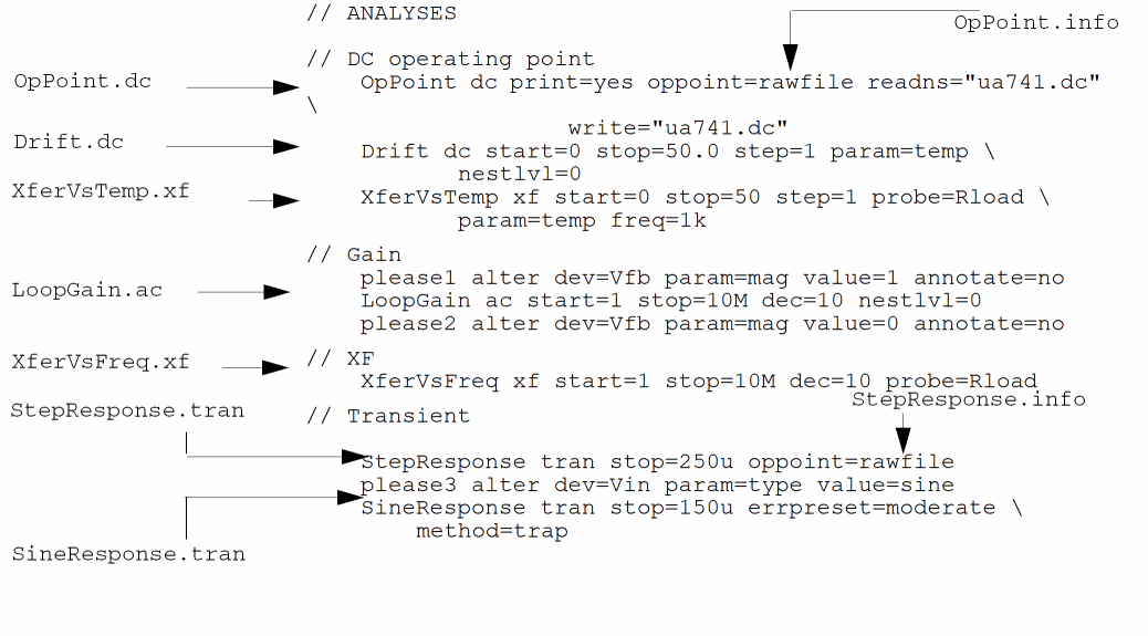
| Results File | Description |
|---|---|
Filenames for SPICE Input Files
If you specify analyses with standard SPICE syntax, the name of the output file for the first instance of each type of analysis is the same as the name shown in the following table:
| SPICE Analysis | Output Filename |
|---|---|
If you request multiple unnamed analyses using SPICE syntax, the names are constructed by appending a sequence integer to the name of the analysis type and further adding the dot extension that is appropriate for the analysis. For example, multiple AC analyses would generate this sequence of files: frequencySweep.ac, ac2.ac, ac3.ac, ac4.ac, and so on.
Specifying Your Own Names for Directories
You might want to specify a name for an output directory that is different from the name of your netlist. (For example, if you use the same netlist in more than one simulation, you probably want different names for the output files.) You can specify names in two ways:
-
You can specify your directory name from the command line or in an environment variable with the
spectrecommand-rawoption. For example, if you want your output directory to be namedtest.circuit.raw, you start your simulation as follows:spectre -raw test.circuit
inputFilename -
You can set the
rawfileparameter of theoptionsstatement. For example, the followingoptionsstatement creates an output directory namedtest.circuit.raw:Setup options rawfile="test.circuit"
Return to top