Create Via Form
Use the Create Via form to specify the settings based on which you want to create vias. The form contains the following common options.
| Field | Description |
|---|---|
|
Lets you select the mode in which you want to create the via: Single, Stack, Auto, or Fast Edit. Environment variable: viaMode
In Auto and Fast Edit modes, the Create Via form does not open automatically. You need to press the |
|
|
Places the vias belonging to adjacent layers on top of each other. |
|
|
Places a via automatically at the intersection of two paths. |
|
|
Opens the Create Via Options Form where you can specify the option for via creation such as the cut spacing method and via definition. |
Single Via Mode
The following table describes the tabs and common options available in the Single via mode on the Create Via form. The availability of a tab depends on the type of via definition that you select, standard or custom.
| Field | Description |
|---|---|
|
Contains all user-defined via parameters and CDF parameters, which are not part of Cadence-predefined via parameters. |
|
|
Lets you create array patterns on vias. This tab is enabled only if the selected via definition is a cdsGenVia. |
|
|
In Single and Stack via modes, you can choose any of the following:
In the Auto mode, when you click on the canvas, the via is placed in the overlap of two shapes. By enabling From Area, rectangular or polygonal, you can define a region in which the layout editor will place the via in all overlapping regions. Environment variable: viaAutoViaCutArrayDirection All the remaining form field values in both the Single and Stack modes are calculated automatically by the Create Via command when you click the overlapping region of two intersecting shapes. In the Single mode, the command calculates the rows, columns, and enclosures, by using the information specified in the form. In the Stack mode, the command calculates the rows and columns of the top via and the spacing, sizes, and enclosures of all the vias in the stack, such that all the vias in the stack fit in the area of overlap between the two intersecting shapes. Environment variable: viaComputeFromMode |
|
|
Enables all vias to be listed in the Via Definition list irrespective of the constraint group selected. |
|
|
Displays the valid viaDefs and valid via variants in a tree-like structure from the active constraint group (set in the Via list in the Layout Editor Options Form). By default, the viaDefs are listed in the same order as specified in the If any filtering options are set up by using the Filter widget, the Via Definition list displays only the viaDefs or via variants that satisfy the filtering options. Each node in the tree represents a standard or custom viaDef. A node with a plus sign (+) represents a parent standard or custom viaDef with child viaVariants. If a parent viaDef is not a valid via in the active constraint group, the viaDef is grayed out and cannot be selected. Choosing a viaDef or via variant from the list selects the via from the effective technology file. |
|
|
Displays the via definition selection widget that lets you define how to filter and sort via definitions. The widget contains the following options:
The search criteria are not retained when you close or hide the Create Via form. |
|
|
Displays the via type and technology library of the viaDef selected in the Via Definition field. The via type can be |
|
|
Opens the Save Via Variant form, where you can change some parameter values of a standard or custom viaDef and then save it as a via variant. You can update the via even after it has been created to use the parent viaDef by using the button on the Edit Via Properties form or the Property Editor assistant. In the Property Editor assistant, the button is visible when you click the ViaDef value column. |
|
|
Lets you associate a net with the via.
|
|
|
Enables you to reset the values in the form to the technology database values if you want to revert from the manually updated parameter values to the defaults. When you first open the Create Via form, the via parameter values are calculated based on the Via Parameters Calculation Mode setting in the Create Via section in the Layout Editor Options Form.
|
|
If you select a via variant from the Via Definition list, the Reset Parameters to list is not available.
Environment variable: viaParamCalcMode |
The following table explains how the parameter values are reset if one of the Reset Parameters to option is selected. The table illustrates scenarios when Compute Enclosures is either on or off.
| Compute Enclosures | Parameter Values | Reset Parameters to | ||||
| Minimum Rules then ViaDef | Minimum Rules | Minimum Rule Enclosures | ViaDef Defaults | ViaDef Default Enclosures | ||
System Tab
The following table describes the fields available on the System tab in the Single via mode of the Create Via form. This tab contains values for standard vias.
| Field | Description |
|---|---|
|
Sets the origin of a via. Cyclic field choices are: |
|
|
Sets the origin point of the via in the X direction when the cyclic field is set to offset. When columns are set to more than one and the cyclic field is set to a direction, X is grayed out and it displays the amount of the directional offset in the X direction. |
|
|
Sets the origin point of the via in the Y direction when the cyclic field is set to offset. When rows are set to more than one and the cyclic field is set to a direction, Y is grayed out and it displays the amount of the directional offset in the Y direction.
For 1x1 via (one row and one column), all Justification values except for offset map to the same point. Therefore, the Justification field on the Edit Via Properties form displays only centerCenter and offset. For a via with one row and more than one columns, |
|
|
This section provides options to specify cut layer settings of the via. |
|
|
Displays cut class choices only if a The following are examples of cut classes:
If you update the Cut Class selection, the values in the fields, such as Rows, Columns, Width, Length, Row Spacing, and Column Spacing, are dynamically updated.  |
|
|
Sets the width and length of the via cut, in user units (typically microns). If a Cut Class is selected, the cut Width and Length are automatically updated to the cut size values defined for that cut class in the |
|
|
Sets the number of rows or the number of columns of via cuts in a via array. You can specify a value up to You can use the swap button to swap the values in the Rows and Columns fields. If the swapped values violate the minimum rules, the spacing and enclosure values are re-calculated based on the Reset Parameters to setting. |
|
|
X sets the distance between the horizontal edge to the edge cuts in a via. Y sets the distance between the vertical edge to the edge cuts in a via. You can use the swap button to swap the values in the Row Spacing and Column Spacing fields. |
|
|
This section provides options to specify enclosure settings. |
|
|
Calculates enclosures automatically. This is on by default. You can deselect this option to manually specify the enclosure values. Environment variable: viaCompuEnclosures |
|
|
Toggles the display of the section in the form that sets the directional enclosure distances on Layer 1, the bottom routing layer, and Layer 2, the top routing layer. The swap button swaps the enclosure values between the first and second layer fields. If the swapped values violate the minimum rules, the enclosure values are re-calculated based on the Reset Parameters to setting. |
|
|
|
|
|
|
|
|
|
Implant layer enclosures cannot be specified for custom vias. |
|
If you manually specify the enclosure values, they are cached as long as they obey the minimum rules. When you update other via parameters in the form, the manually specified enclosure values are not re-calculated unless they violate the minimum rules. Note that implant layer enclosures cannot be specified for custom vias. |
|
|
This section appears in the Create Via form if you select a cdsVia from the Via Definition list. |
|
|
Enables you to select the purpose for the metal layers. The purposes in this list are populated from the layer purposes defined in the |
|
|
Enables you to select the via layer purpose. By default, it displays the As primary value to indicate the same purpose as selected in the Primary list. |
|
|
Enables you to select the implant layer purpose. This list appears only if any implant layers are defined for the selected |
User Defined Tab
This tab contains all user-defined via parameters and CDF parameters, which are not in the set of Cadence predefined via parameters.
In the case of cdsVia, this tab displays the Pcell parameters that exist on the via. You can change the parameters as required, but the Create Via form does not perform any checks for them.
Cut pattern Tab
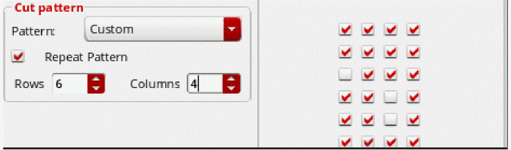
The following table describes the fields available on the Cut pattern tab of the Single via mode on the Create Via form. Use this tab to create cut patterns on via arrays.
| Field | Description |
|---|---|
|
Displays the number of rows in a via array. This is a read-only field that displays the number of rows specified in the Rows field on the System tab. Environment variables: viaRows |
|
|
Displays the number of columns in a via array. This is a read-only field that displays the number of columns specified in the Columns field on the System tab. Environment variables: viaColumns |
|
|
Lets you select a predetermined pattern, such as Custom, Via Def, All On, All Off, Chess Board, H-V Stripes, H Stripes, V Stripes, Top, Bottom, Left, Right, U-L Corner, U-R Corner, L-L Corner, L-R Corner, and Cross. You can now define the default cut pattern for each standard via in the standardViaDef section of the DFII ASCII techfile. This default cut pattern is reflected on the Cut pattern tab of the Create Via form. |
|
|
Repeats the pattern specified in the Pattern field for the number of rows and columns specified in the Rows and Columns fields. If Repeat Pattern is not selected, the values in the Rows and Columns fields are the same as the values in the Via Rows and Via Columns fields, respectively. |
|
|
Sets the number of rows of the repeated pattern. If Repeat Pattern is not selected, this field is disabled. |
|
|
Sets the number of columns of the repeated pattern. If Repeat Pattern is not selected, the field is disabled. Depending on the number of rows and columns you specify in the Rows and Columns fields the row x column matrix is depicted by check boxes. You can select or deselect the check boxes to define the cut pattern that you want.
If the number of rows and columns exceeds 10, then the cut pattern is not displayed on the Cut pattern tab of the Create Via form.
 |
Array Pattern Tab
The following table describes the fields available on the Array pattern tab of the Single via mode on the Create Via form. Use this tab to create array patterns on vias. The tab is enabled only if the via definition selected in the Via Definition field is a cdsGenVia.
Stack Via Mode
The following table describes the options available in the Stack via mode on the Create Via form.
| Field | Description |
|---|---|
|
Lets you select one of the two layers between which you want to place the via stack. The layer selected in the End Layer list does not appear in the Start Layer list. |
|
|
Lets you select one of the two layers between which you want to place the via stack. The layer selected in the Start Layer list does not appear in the End Layer list. |
|
|
Sets the origin of a via. Cyclic field choices are: |
|
|
Sets the number of rows and columns for the top via in the via stack. The default number of rows and columns is 1. Rows and columns cannot be specified for the individual vias in the via stack; they apply to the complete via stack. The command calculates the rows and columns of the vias below the top via in such a way so that all vias in the stack coincide. Environment variables: viaStackRows and viaStackColumns If the via stack contains custom vias, the default rows and columns of the custom vias are used for creating the via stack. You cannot modify the rows and columns of custom vias by using this form. |
|
|
Lets you select viaDefs for each layer pair between the specified Start Layer and End Layer. For each layer pair, the drop-down list displays the available viaDefs. The viaDefs are populated from the |
|
|
Displays cut class choices only if a cutClasses constraint has been defined for the cut layer of the selected viaDef in the |
|
|
Turns the via 90 degrees counterclockwise. You can also click the middle mouse button to rotate the via. |
|
|
Mirrors the via or via stack along the X axis. You can also press |
|
|
Mirrors the via or via stack along the Y axis. You can also press |
For descriptions of the common options Compute From, Constraint Group, and More Options, refer to Single Via Mode.
Auto Via Mode
The following table describes the options available in the Auto via mode on the Create Via form. In the auto via mode, vias are automatically placed at the intersection of two paths.
| Field | Description |
|---|---|
|
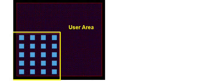
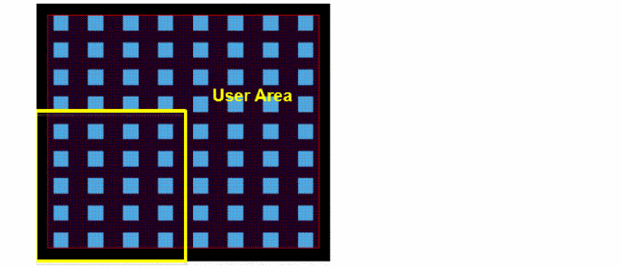
Uses the entire overlap to create the via. If this option is not selected, an intersection between the user area and the overlap box is used to create the via.
Environment variable: |
|
|
Displays cut class choices only if a Environment variable: viaCutClassInAuto |
|
|
Specifies the alignment of the via using the alignment choices: auto, top-left, top-center, top-right, center-left, center-center, center-right, bottom-left, bottom-center, bottom-right, edge-align, two-edge-align, and two-edge-align-center. The default is auto .
Environment variable: |
|
|
Specifies the preferred orientation for the cut class as one of the following: auto, horizontal, vertical, or uniform in stack.
Environment variable: |
|
|
Specifies the preferred direction for the cut box as one of the following: auto, horizontal, or vertical. Environment variable: viaAutoViaCutArrayDirection |
|
|
Specifies the minimum number of cuts to be automatically created for any overlapping area between two shapes. Environment variable: viaAutoViaMinNumCuts |
|
|
Searches the overlap with the same number of transitions or less than the specified number. You can specify the value of the maximum stack depth. If you specify Environment variables: viaAutoViaEnableMaxStackDepth and viaAutoViaMaxStackDepth |
|
|
This section lets you define the via settings like whether to prevent DRC violations and show previews and hints. |
|
|
Lets you define the fill style when the overlap is polygonal. You can choose to either fill in all the tiles of the polygon overlap, Fully, or only the tile under the pointer, Partially. |
|
|
Specifies the alignment of cuts between different tiles of a polygonal overlap. When this option is enabled, cuts between different tiles of a polygonal overlap are aligned. When this option is disabled, the polygonal overlap is decomposed into a set of largest tiles and vias are created independently in each tile, which may result in cuts not being aligned between different tiles. Environment variable: viaAlignCuts |
|
|
Prevents the creation of a via if it introduces DRC violations on the overlap. If this option is not selected, the via is created even if it introduces DRC violations on the overlap. Environment variable: viaPreventDRCOnOverlap |
|
|
Prevents the creation of a via if it introduces DRC violations with the neighboring shapes. If this option is not selected, the via is created even if it introduces DRC violations with the neighboring shapes. Environment variable: viaPreventDRCWithNeighbors |
|
|
Prevents the creation of a via if it is larger than the overlap. 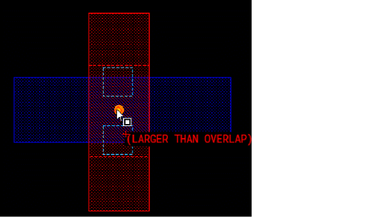 |
|
|
Shows a preview of the via that will be created. 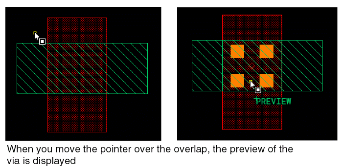
Environment variable:
In Auto and Fast Edit via creation modes, a label PREVIEW is displayed close to the pointer. This ensures that you are aware that the displayed via is a preview and not a real via existing in the layout design. When you click the overlap area, the via is created and the PREVIEW label disappears.
If the layout editor is not able to display the preview of the via in a reasonable time, the label PREVIEW TOO COMPLEX is displayed. In the Fast Edit mode, the vias are updated instead of being re-created, wherever possible.
For details on auto via preview and fast edit via creation mode, see the video Auto Via Preview & Smart Auto Via.
|
|
|
Displays the Auto Via Preview Bindkeys hint box on the canvas.
Environment variable:
|
Fast Edit Via Mode
Use the Fast Edit via mode if you want to perform interactive via editing. The following table describes the option available in the Fast Edit via mode on the Create Via form.
| Field | Description |
|---|---|
|
Lets you use fast edit command from a set of selected vias. Environment variable: viaFastEditFromSelectedVias |
The other options available in the Fast Edit via mode are same as the Auto via mode options. For a description of the common options, refer to Auto Via Mode.
Related Topics
Return to top