


|
|
|||||||||
|
|
|
|
|
|
|
|
|
|
|
The Virtuoso® UltraSim™ simulator is a fast and multi-purpose single engine, hierarchical simulator, designed to verify analog, mixed signal, memory, and digital circuits. The simulator can be used for functional verification of billion-transistor memory circuits and for high-precision simulation of complex analog circuits. Based on hierarchical simulation technology, the Virtuoso UltraSim simulator is faster and uses less memory than traditional circuit simulators, while maintaining near SPICE accuracy.
The main features of the Virtuoso UltraSim simulator include:

|
Support of Spectre® and HSPICE netlist file formats, Verilog-A language, post-layout detailed standard parasitic format (DSPF) and standard parasitic exchange format (SPEF) netlist files, and structural Verilog® netlist files. |
|
|
Support of digital vector file format, and Verilog® value change dump (VCD) and extended VCD (EVCD) digital stimuli formats. |
|
|
Matlab toolbox to import PSF or SST2 data into MATLAB® (refer to the Spectre Circuit Simulator RF Analysis User Guide for more information). |
|
|
Standalone measurement tool to apply .meas to existing SST2 or FSDB waveform files. |
Refer to the following Cadence documentation for more information about these extended analyses:
|
|
Virtuoso AMS Designer Simulator User Guide describes AMS UltraSim for Verilog/VHDL co-simulation with NCSIM. |
|
|
Virtuoso Analog Design Environment L User Guide describes UltraSimVerilog and mixed signal co-simulation with VerilogXL. |
|
|
Power IR/EM User Guide describes the data preparation and steps necessary for power-grid and electromigration (EM) analysis using the Virtuoso Power system (VPS) product, Power IR/EM. |
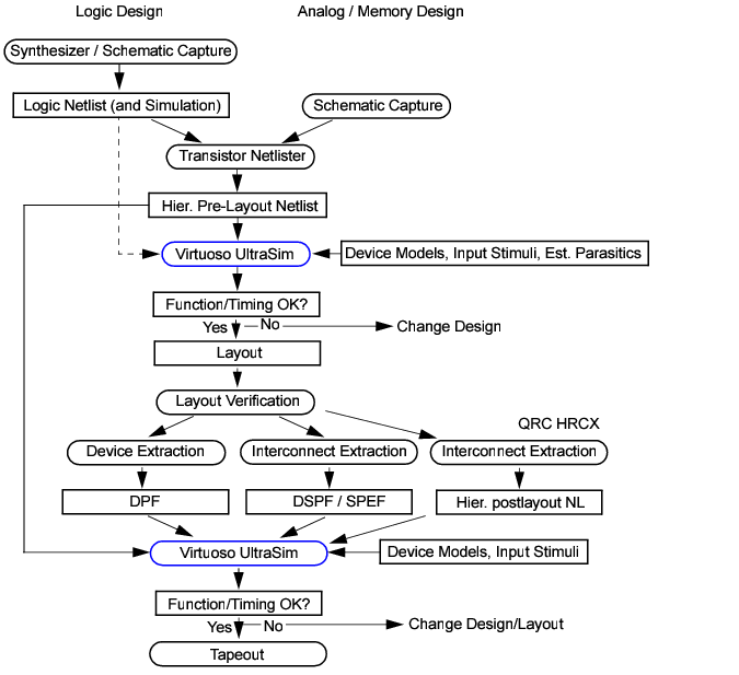
The Virtuoso UltraSim simulator can be used for pre- and post-layout simulation of analog, mixed signal, memory circuits, and logic designs. Figure 1-1 shows how the simulator fits into the IC design flow.
Figure 1-1 Virtuoso UltraSim Simulator in IC Design Flow
ultrasim [-f]<circuit> [Options]
Note: You need to set the path to your_install_dir/bin prior to running the Virtuoso UltraSim simulator.
Table 1-1 lists the Virtuoso UltraSim simulator command line options.
Note: Ensure that the file argument is specified with the .usim_emir statement when you set the value 2 for autoemir. |
|||||||
|
[-f] circuit |
Specifies the circuit netlist filename (the netlist file can be compressed using gzip - see "Compressed Netlist File" for more information) |
||||||
|
+config file |
ultrasim +config usim_opt1.cfg input.scs Where, usim_opt1.cfg is the configuration file. |
||||||
|
+optionName value | +optionName=value | +optionName +value |
|||||||
|
Specifies a global UltraSim usim_opt option and its value. For example: ultrasim +spfcaponly on test.sp |
|||||||
|
-libpath path |
|||||||
|
+log file |
Sends the log output information to the standard output (shell), and the specified file |
||||||
|
=log file |
|||||||
|
Specifies a duration (in seconds) for which the software should wait to check-out a license. When you set this option to 0, the Virtuoso UltraSim simulator waits for a license until it is available. Default: 900 seconds Note: +lqt, the abbreviated form of +lqtimeout, can also be used. |
|||||||
|
Reports the number of required tokens in the log file. Note: +lrpt can be used as an abbreviation of +lreport. |
|||||||
|
-raw rawDir |
Specifies the directory in which all parameter storage format (PSF) files are created |
||||||
|
-outdir outDir |
Specifies the directory in which all of the output files are created |
||||||
|
-outname filename |
Specifies the base filename which is used when files are created |
||||||
|
Displays waveform data in fmt format (possible values for fmt include psf, psfxl, sst2, fsdb, tr0ascii, or wdf; only one entry is allowed) |
|||||||
|
Specifies multiple waveform formats or user-defined output format; use a colon (:) as a delimiter to specify multiple formats |
|||||||
|
Note: +lsusp, the abbreviated form of +lsuspend, can also be used. |
|||||||
|
Checks licenses in a specific order (use : between license feature names when defining the order) |
|||||||
|
Turns on multithreading capability and assigns the simulation jobs to the specified N number of threads. N can be an any integer value between 1 and 16. +mt, the abbreviated form of +multithread, can also be used. Note: There should be no space before and after the assignment operator = when you specify the number of threads. When N is not specified, the UltraSim simulator automatically detects the number of processors and selects the appropriate number of threads to use. By default, the UltraSim simulator does not use multithreading. Important: The multithreading functionality is available only for A, S, and MX simulation modes. |
|||||||
|
Turns off multithreading capability. Note: -mt, the abbreviated form of -multithread, can also be used. |
|||||||
|
-processor list |
Sets the CPU affinity of a process similar to the Linux taskset command. You can specify a numerical list of processors that may contain multiple items, separated by comma. For example: |
||||||
|
-top subckt |
|||||||
|
-I dir |
Specifies the search dir directory for .include files |
||||||
|
-cmd cmdfile |
|||||||
|
-cmiconfig file |
|||||||
|
Specifies that the circuit netlist file is in Spectre format |
|||||||
|
-vlog verilog_file |
Specifies that the circuit netlist file is in Verilog format |
||||||
|
Possible values for -ahdllint are: no, warn, and error. You can enable the AHDL linter feature in UltraSim, as follows: ultrasim -ahdllint netlist.scs For more information on the AHDL linter feature, refer to the Spectre Classic Simulator, Spectre Accelerated Parallel Simulator (APS), and Spectre Extensive Partitioning Simulator (XPS) User Guide. |
|||||||
|
|

|
You can use the ULTRASIM_DEFAULTS environment variable in your .cshrc file to specify a default value of your choice for UltraSim command-line options. The syntax of this environment variable is: |
setenv ULTRASIM_DEFAULTS "optionName1 value optionName2 value ..."
For example, to set the default value of +lqtimeout and +lorder command-line options, use the following setting:
setenv ULTRASIM_DEFAULTS "+lqtimeout 0 +lorder MMSIM"
|
|
If the log file option is not specified, the Virtuoso UltraSim simulator automatically generates an output file named circuit.ulog. |
|
|
If [+=]log is specified, then the simulator always uses the option during simulation. This option only affects the name of the log file. If a path is not given for [+=]log, the final path for the log file follows the setting specified by the -outdir option. If [+=]log is not specified, the default ulog file follows the -outdir and -outname options. |
|
|
If -raw and -outdir are specified, -raw is overwritten by the simulator. All output files are placed into the directory specified in -outdir, unless +log, usim_save, or model_lib is used to specify the path for the corresponding files. A new directory is created if one does not already exist. |
|
|
If -outname is specified, all the output files using the netlist file name as a prefix are changed to the name defined in -outname. |
In the following example, the Virtuoso UltraSim simulator writes the information into a log file named circuit.log.
ultrasim circuit.sp =log circuit.log
In the next example, the information is displayed on a standard output display device (same result if -log is not specified in the command).
In the next example, the Virtuoso UltraSim simulator writes the information into a log file named circuit.log and also displays it on a standard output display device.
ultrasim circuit.sp +log circuit.log
The Virtuoso UltraSim simulator supports post-processing measurements based on waveform data from a prior simulation run. To perform measurements on an existing waveform file, add a .measure statement to the original netlist file and rerun the simulation using the -readraw statement (the regular simulation process is skipped). The post-processing measurement results are reported in .pp.mt0 and .pp.meas0 files. The default post-processing log file name is .pp.ulog.
The -readraw statement can be used to perform measurements based on signals or expression probes.
In the following example, the Virtuoso UltraSim simulator saves the v(x1.out) and i(x1.out) signals in the SST2 waveform top.trn file.
To perform a power calculation, the following measurement statement is added to the top.sp file.
.measure tran power avg v(x1.out)*i(x1.out) from=0ns to=1us
Note: You can also put .measure statements in a file (for example, measure.txt) and include it in the top.sp file.
To start the post-processing measurement, use the following statement.
ultrasim -readraw top.trn -spectre top.sp
The measurement results are reported in the top.pp.mt0 and top.pp.meas0 files.
To run Virtuoso UltraSim 64-bit software,
|
|
Use the -debug3264 -V command to check your system configuration: |
$your_install_dir/bin/ultrasim -debug3264 -V
You can use the information to verify if the 64-bit version is applicable to your platform, if the 64-bit software is installed, and whether or not it is selected.
|
|
Verify that all required software patches are installed by running checkSysConf (system configuration checking tool script). The script is located in your local installation of Cadence software: |
$your_install_dir/bin/checkSysConf MMSIM7.0
The script is also available on the Cadence Online Support system.
|
|
Set the CDS_AUTO_64BIT environment variable {all|none|"list"|include: "list"|exclude:"list"} to select 64-bit executables. |
|
|

|
all invokes all applications as 64-bit. |
The list of available executables is located at:
$your_install_dir/bin/64bit
|
|
|
none invokes all applications as 32-bit. |
|
|
|
"list" invokes only the executables included in the list as 64-bit. |
"list" is a list of case-sensitive executable names delimited by a comma (,), semicolon (;), or colon (:).
|
|
|
include:"list" invokes all applications in the list as 64-bit. |
|
|
|
exclude:"list" invokes all applications as 64-bit, except the applications contained in the list. |
Note: If CDS_AUTO_64BIT is not set, the 32-bit executable is invoked by default.
Example
setenv CDS_AUTO_64BIT ultrasim
setenv CDS_AUTO_64BIT "exclude:si"
All 64-bit executables are controlled by a wrapper executable. The wrapper invokes the 32-bit or 64-bit executables depending on how the CDS_AUTO_64BIT environment variable is set, or whether the 64-bit executable is installed. The wrapper also adjusts the paths before invoking the 32-bit or 64-bit executables. The wrapper you use to launch the executables is located at your_install_dir/bin.
Note: Do not launch the executables directly from the your_install_dir/bin/64bit or your_install_dir/bin/32bit directory.
Example
$your_install_dir/bin/ultrasim
The Virtuoso UltraSim simulator supports a common configuration file called ultrasim.cfg, enabling you to set the default options for the simulator. This file can be passed into UltraSim with the +config command line option, or it has to be located in one of the following three locations (listed as per search order):
|
|
Home directory ($HOME). |
|
|
Virtuoso UltraSim simulator installation directory ($ULTRASIM_ROOT). |
This allows the Virtuoso UltraSim simulator to be configured by you, by the site, or by the project. The Virtuoso UltraSim simulator processes only the first ultrasim.cfg it reads. That is, the ultrasim.cfg in the netlist file directory overwrites the ultrasim.cfg in $HOME and the Virtuoso UltraSim simulator installation directories. The ultrasim.cfg file can contain the following types of commands:
|
|
Spectre tran, options, and save commands. |
|
|
HSPICE .tran, .options, and .probe commands. |
Note: If Spectre syntax is used in the ultrasim.cfg file, simulator lang=spectre needs to be specified at the beginning of the file.

|
Command-line options specified in the +optionName=value format (highest priority). For example: |
%>ultrasim +speed=2 +rshort=2 +cgnd=1e-16 input.scs
Important: You can only set global options using the above format.
|
|
Configuration file (containing the UltraSim simulator options) specified using the +config command-line option. For example: |
%> ultrasim +config usim_opt1.cfg input.scs
Where, the usim_opt1.cfg file contains the UltraSim simulator options.
|
|
Netlist file using .usim_opt statements. |
For more information on how to set the UltraSim simulator options in the netlist file, see Setting Virtuoso UltraSim Simulator Options in Netlist File.
|
|
Configuration file (ultrasim.cfg) located in the home, work, or installation directory (lowest priority). |
For more information on where the ultrasim.cfg file can be located and the priority using which the configuration file is processed with respect to its location, see the Virtuoso UltraSim Simulator Configuration File section.
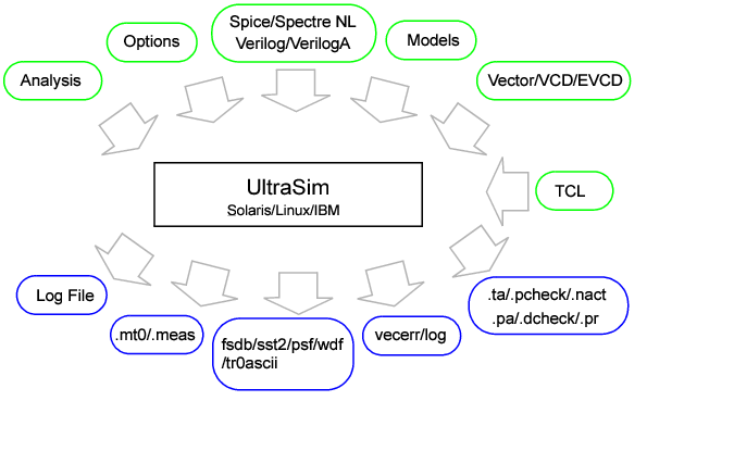
The Virtuoso UltraSim simulator recognizes Spectre, SPICE, Verilog-A, and structural Verilog netlist file formats. Figure 1-2 gives an overview of the input and output data required for simulation with the Virtuoso UltraSim simulator. The simulator also supports all major Spectre and SPICE device models (see Chapter 2, "Netlist File Formats," for more details). Digital vector file format and VCD/EVCD stimuli are described in Chapter 11, "Digital Vector File Format" and Chapter 12, "Verilog Value Change Dump Stimuli." The Virtuoso UltraSim simulation options for optimizing simulation accuracy and performance are located in Chapter 3, "Simulation Options."
Figure 1-2 Virtuoso UltraSim Simulator Input/Output Files Diagram
In addition to a log file, the Virtuoso UltraSim simulator creates several output files that contain waveforms, measurements, and analysis results. Each output file has an extension followed by a number. The output files are defined in Table 1-2 below.
For mt files, the number following the file extension corresponds to the .alter number. For example, if there are two .alter blocks in the netlist file, the mt files are called .mt0, .mt1, and .mt2. The naming convention is HSPICE compatible.
For all other output files, the number corresponds to the number of times the transient analysis was run. For example, if the main netlist file block specifies two different temperatures in the .temp command card, and there is an .alter block that modifies the original .temp command card and specifies new temperature values, then the transient analysis for this netlist file needs to be run three times. All output files generated from the first run would not have a number after the extension. For example, the FSDB file is named circuit.fsdb. The output files generated from the second and third runs are named circuit.fsdb1 and circuit.fsdb2, respectively.
The <output-type> syntax can be either V, I, X0, or any other output type supported by the Virtuoso UltraSim simulator, and <node> is the name of the node specified in the probe statement.
|
|
<node> for voltage probes |
|
|
<elem>:<num> for current probes |
|
|
<node>:<output-type> for all other output types, where <node> is the name of the node specified in the probe statement and <num> is the branch of the element or node for which the waveform is needed (default <num> is 1) |
If the input netlist file contains SPICE and Spectre syntax, then the default for the waveform name is Spectre syntax. You can override the default behavior of the waveform syntax by using the wf_spectre_syntax option.
Setting this option to 1 in the input netlist file forces the output waveform names to follow Spectre syntax, independent of whether the input netlist file is in SPICE, Spectre, or both formats. If the option is set to 0, the output waveform names follow SPICE syntax, independent of the input netlist file format.
Note: The Virtuoso UltraSim simulator waveform output generated in the analog design environment (ADE) is always in Spectre syntax, irrespective of the input netlist file format or the wf_spectre_syntax option.
The Virtuoso UltraSim simulator supports two types of return codes: 0 and 1. A return of 0 indicates the simulation was successfully completed and a return of 1 indicates the simulation failed.
|
|
An error message reports a condition that the simulator cannot resolve (if the error is severe, it may cause the simulator to stop completely). |
|
|
A warning message reports an unusual condition that does not adversely affect the simulation. |
|
|
An info message presents information that does not fall into either of the other message categories (info messages are generally used to give the status about a process that is running). |
The Virtuoso UltraSim simulator tutorials provide examples to help you get started with the simulator. Running the tutorials is recommended to obtain hands-on experience in using the Virtuoso UltraSim simulator features and options. To access the tutorials, see the ultrasim_install_dir/tools/ultrasim/examples directory, which contains the UltraSim Workshop (UltraSim_Workshop.tar.gz file). The workshop provides examples for each UltraSim feature including design checks and EMIR analysis.
