AMS Designer allows usage of a digital module inside DSPF for post-layout simulation. Using DSPF-in-the-middle speeds up mixed-signal post-layout simulation and it enables running verification as early as possible.
The following diagram illustrates a DSPF subcircuit.
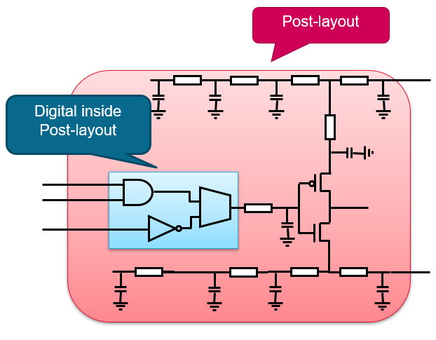
In this diagram, the outer block contains a circuit topology, myRingOsc16. The inner blue block represents a sub-subcircuit, myBufL8. Consider that you need to replace myBufL8 with a Verilog module because it is faster to compute Verilog modules. To bind myBufL8 as Verilog module instead of a DSPF subcircuit, perform the following steps:
- Open the
.scsfile. - Add the
dspf_includecommand with name of the DSPF file and theblackboxkeyword. Add other keywords, as required.dspf_include "./dspf/myRingOsc16_BB.dspf" blackbox="myBufL8" bus_delim="<> []" - To change the binding from SPICE to Verilog, point to the DSPF in the
configstatement and switch the binding inside DSPF.
//AMSD Blockamsd{
//IE Definition Defaultie vsup-1.8 discipline=logic//Partitioningportmap module=myBufL8 reffile=muBufL8.v porttype=orderconfig inst=myRingOsc16.TB.I0.XI0\/XI0\/XI0 use=hdl}
Similar to the SPICE-in-the-Middle flow, you can further configure the blackbox instance myRingOsc16.TB.I0.XI0\/XI0\/XI0 with mixed-signal modules, within an amsd block