5
Changes to Environment Objects and Shapes
Differences Between CDB and Virtuoso Studio Design EVirtuoso Studio design environmentnvironment Objects
Virtuoso Studio design environment Objects
CDB and Preview Conventions for Identifying Objects
Controlling Display and Selection of Objects
Required Technology File Layers and Purposes for OpenAccess Objects
Bounding box for Net Expression Text Display Incorrect in OpenAccess
Converting Start and Stop Angles for an Arc
Querying an Arc for Its Bounding Box
Querying an Arc for Its Start and Stop Angles
Bounding Boxes of Labels and Text Displays
Differences Between CDB and Virtuoso Studio Design EVirtuoso Studio design environmentnvironment Objects
In DFII on CDB applications, layer-purpose pairs (LPPs) are used to represent the purpose of a shape. For example, a rectangle with the conventions of the LPP, metal1 boundary is used to define the shape for the specific purpose of a boundary. When a shape using conventions originates from CDB and is translated into a Virtuoso Studio design environment application, these conventions of shapes on specific LPPs do not apply.
When translating data from CDB to the Virtuoso Studio design environment, shapes such as boundaries and blockages are converted to objects. The selection, display, and editing is object based. These objects have attributes and can be created and edited through a GUI or through SKILL. Although these objects do not use LPPs to represent their purpose, they are assigned to an LPP to allow display.
Objects in place and route tools such as SoC Encounter, such as a rows and track patterns are supported in the Virtuoso environment. They are assigned LPPs for display, and depending on the application, creating and editing is allowed.
Below is a list of objects supported in the Virtuoso Studio design environment.
For a full listing of each class in the OpenAccess API, go to the URL
For a description of CDB conventions for these objects, see CDB and Preview Conventions for Identifying Objects.
Virtuoso Studio design environment Objects
Throughout the documentation concerning there are references to objects according to how they are used in an application or flow. Below are the list of terms used through out the Cadence Help documentation and their descriptions.
Interconnect Objects
Path
A single layer object. Paths can be created using the Create - Path command or can be optionally selected as an element to be used when creating wires. Paths support anyAngle mode. When used to do non-orthogonal routing, paths can lead to off-grid vertices being created, depending on the width and angle being used.
Wire
A contiguous string of paths, segments (pathSegs), and vias used to connect same net instance terminals and pins of the cellview. Wires are not directly associated with a database object.
For information about creating wires, see
pathSegs
A specialized shape-based object represented by a specified width, a layer-purpose pair, and a two-point routing segment with a style associated with each of the points. Pathsegs can be orthogonal or diagonal and can be used to create on-grid 45 degree wires. Custom end styles containing octagonal edges are used in diagonal pathSegs to pull all vertices on grid.
For information about accessing pathSeg attributes, see
Segment of Path
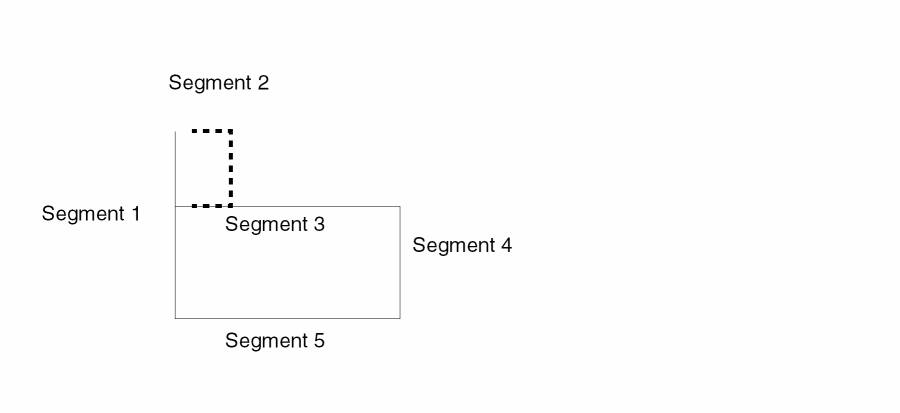
Section of an individual path object.
Route
A route is associated with the OpenAccess object oaRoute. Routes are containers that can hold the objects pathSeg, vias, and guides.
A guide specifies a connection between two objects that are intended to be wired together. Routing nets usually replaces guides with wires, or routes. Currently, guides are only supported at the API level.
Via
In CDB, a contact is implemented as a pre-defined Pcell, which is a special instance. Virtuoso Studio design environment applications will not recognize a via placed as a instance. In the Virtuoso environment, vias are first class objects. Vias and instances (specifically contacts placed as instances) are considered two different types of objects in OpenAccess. Vias correspond to the OpenAccess oaVia class and instances correspond to the oaInst class. The CDB menu item Create – Contact is replaced with Create – Via in the Virtuoso environment.
Existing user code that refers to, or searches for vias as instances must be changed to search for vias as first class objects.
All CDB contacts defined in technology file are translated into via definitions. Via definitions (viaDefs) define via cellviews in a technology database. There are two types of via definitions; customViaDefs and standardViaDefs.
For information about how vias are mapped, see Mapping of CDB Devices.
If your CDB design contains vias with master cellviews defined in the design library rather than the technology library, you must list the vias in a mapping file and refer to the mapping file when migrating the library from CDB to OpenAccess.
Standard Via
The standard via references a standard via definition which is implemented by the oaStdViaDef object. The standardViaDefs has an unique name and is associated with two layers and a list of via parameters with default values. It is an object that is predefined by the database.
Custom Via
A custom via is an instance of a custom via definition which is implemented by the oaCustomViaDef object. A custom via has an unique name and is associated with a via master. The via master may be parameterized and its parameters are specified through the use of an oaParamArray object.
For information, see
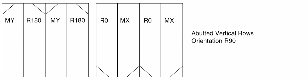
Rows
A row represents a location for the placement of standard cells, macros, or device and is a repetition of the site element in a given direction (horizontal or vertical). Each row is associated with a siteDef. All sites in one row must be the same size. The display of row objects can be turned on or off and the snapping of instances to row can be controlled. Rows are drawn using the display attributes for LPP row boundary.
Rows define a pattern of a sites and are generated by the ROW statement in a DEF file. Rows are drawn as a rectangle with a diagonal line in the same corner as the origin which shows the row orientation.
Two types of rows exist; horizontal and vertical rows. Horizontal rows are of the orientation R0. Vertical rows are of the orientation R90.
There are four possible site orientations, R0, MX, 180, and MY for horizontal and vertical rows. It is the orientation of the row with the site which defines the type of row.
Table 5-1 Horizontal Rows
| Row Orientation | Site Orientation |
|---|---|
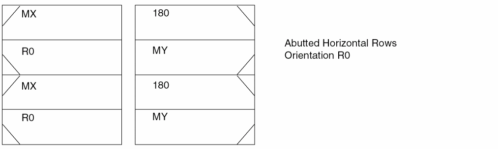
Table 5-2 Vertical Rows
| Row Orientation | Site Orientation |
|---|---|
Creating Rows Using SKILL
Rows can be created using DEF In and though SKILL. The following example creates a horizontal row, with the site orientation of MX, at the origin point of 0:0, with 50 sites using SKILL.
cv = geGetEditCellView()
tf = techGetTechFile(cv)
site1 = techCreateScalarSiteDef(tf "site1" "core" 5 5)
dbCreateRow(cv site1 "row1" list(0 0) 50 "MX" "R0")
For more information, see
Sites
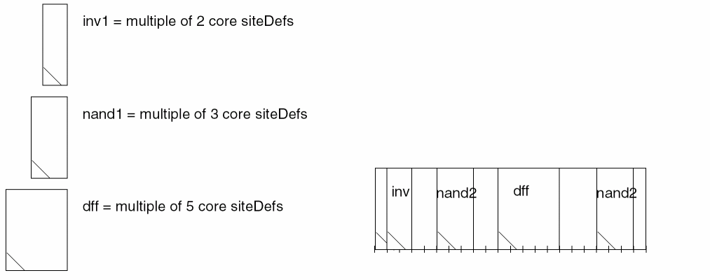
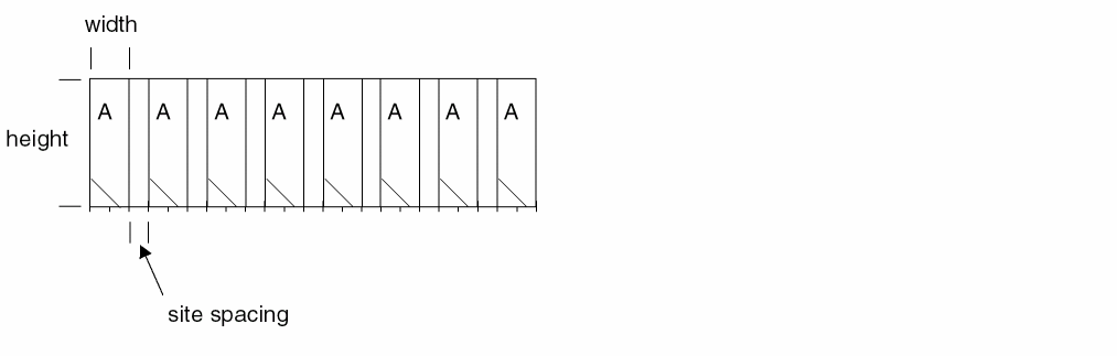
Site definitions (siteDefs) are technology objects which are the basic elements from which placement rows are constructed.
Core sites are used for standard cell placement in rows. Cell widths must be a multiple of the site width. If there are multiple standard cell heights, a site must be defined for each standard cell height. A row is basically a one dimensional array of a given site. A scalar site definition defines the width, height, and allowable symmetry of each placement location in a row.
The array site definitions, are a two dimensional array of siteDefs. T
The siteRef also holds an additional transform parameter that provides the capability of introducing empty 2 dimensional space between sites - which will need to be considered as a sitePattern defines the pre-determined set of sites. This empty space transform is available in both oaScalarSiteDef and in oaArraySiteDef.
The array site definition defines a pattern of scalar sites. It has a pre-determined set of sites that are used to place a set of cells as part of a row. This type of site is primarily used in gate-array designs. The array site definition references the sitePattern definition to determine to the set of sites. Each sitePattern is a named site reference (siteRef) to an oaScalarSiteDef.
The pattern that is specified will determine whether a cell can be placed or not. In the following example the pattern is AABC. You can place cells with one of the following patterns.
"A" "B" "C" "AA" "AB" "BC" "AAB" "ABC" "AABC"
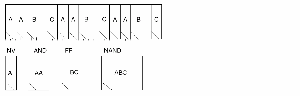
prCellType with the value of site, the cellview will be mapped to a siteDef on the OpenAccess database. The technology file siteDefs section will be updated accordingly.
For more information, see
Blockages
A blockage indicates an area in a design in which a certain type of object is not allowed to be placed. There are three types of blockages, area blockage, layer blockage, and area halo.
- An area blockage is used to prevent instances from being placed within a specific area.
- A layer blockage represents an area on a given layer where an instance cannot be placed. In Virtuoso, a layer blockage cannot be of type placement.
- An area halo is associated with an instance or a prBoundary to represent an extended area around the master’s prBoundary. An area halo extends the area around a instance or a prBoundary in four orthogonal directions. The offsets in these directions can be different.
Owners
Different types of blockages can have different owners.
| Type of Blockage | Type of Owner | |
|---|---|---|
Blockage Types
Area halo blockages can only be of type placement. Area and layer blockages support all of the following blockage sub-types except placement.
routing
placement
wiring
fill
slot
pin
feedthru
Screen
For information about accessing blockage attributes, see
Boundaries
The CDB to OpenAccess migration converts CDB boundary shapes on layers to an OpenAccess prBoundary object. All boundary objects are assigned to layer purpose pairs (LPP) to allow display. The LPPs are used for object display and selection and should be set to not valid in the LSW. Meaning the LPPs should not be available for shape drawing from the Layers panel of the LSW. Control selection and display of objects through the Object panel of the LSW. For a list of required technology file layers for OpenAccess objects, see Required Technology File Layers and Purposes for OpenAccess Objects.
There are four types of boundary objects, area boundary, snap boundary, prBoundary, and cluster boundary.
- An area boundary specifies an area in a block for a specific purpose. Area boundaries are named. A block can have multiple area boundaries, each identified by its name.
- The snap boundary is used by tools to place instances of the cellview in rows. Depending on rotation and symmetry, the appropriate corner is snapped to the site in the row.
- The cluster boundary specifies the area in which a cluster of objects (group of objects) that are associated with a cluster should be placed.
-
The prBoundary is used to represent the boundary of a block for place-and-route applications. Two attributes have been added, a coreBoxSpec and an IO box. Both attributes are mainly used by Soc Encounter. Currently, Virtuoso tools do not use the coreBoxSpec and the IO box.
A coreBoxSpec defines a rectangular grid of sites (a row of rows) within the prBoundary which defines how physical rows, and cells within the rows, can be placed in the prBoundary.
An IO box, together with the core box, indicates the area for the IO cells.
In the example below, the prBoundary has an IO box and a coreBox. The coreBox has four horizontal rows of siteDef A.
All rows are separated by a distance row spacing. Every odd numbered row is flipped.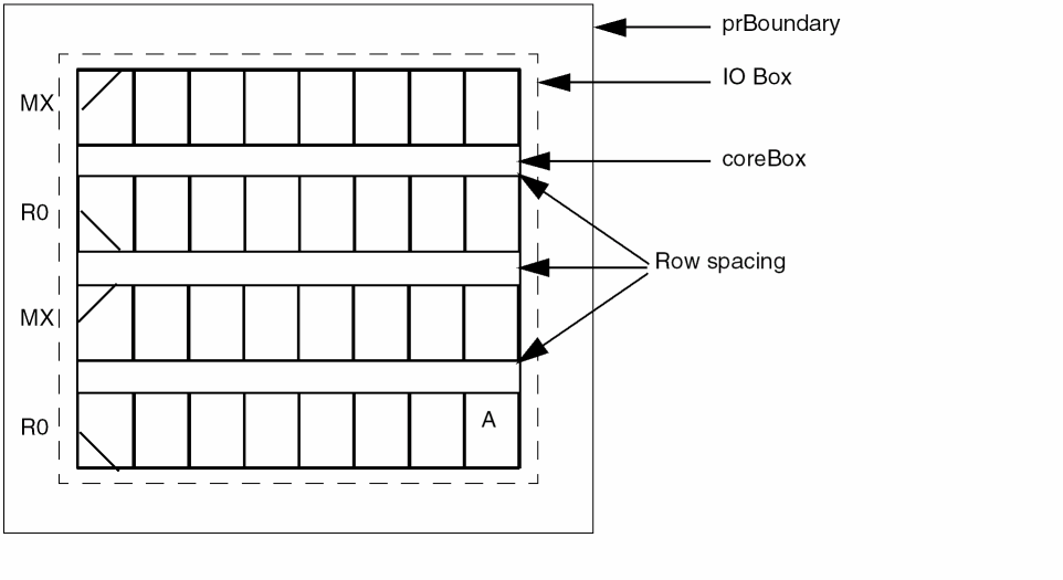
The number of rows and row geometry is computed based on the overall bBox of the coreBox and the siteDef of the coreBox. API is available to retrieve the number of rows and bBox of each row.
For information about accessing boundary attributes, see
Mapping Shape Based Boundaries
Shapes such as boundaries on layers are mapped to an OpenAccess prBoundary object. The following describes how to map CDB boundary shapes on specific layers to boundary objects.
In CDB, prBoundaries are shapes which use the convention of LPPs to identify them as boundaries. In CDB you can define spacing rules to specify data to boundary relationships. For example,
( minEnclosure( "prBoundary" "boundary" ) ( "nwell" "drawing" ) 0.4 )
( "minEnclosure" "prBoundary" "metal1" 0.3 )
( "minExtension" "prBoundary" "metal3" 0.5)
In the Virtuoso Studio design environment, prBoundaries are objects that do not use conventions to define their purpose. When translating data to OpenAccess, prBoundaries defined as shapes on layers, are mapped to prBoundary objects. The constraints Minimum Boundary Extension Constraint and Minimum Boundary Interior Halo Constraint are used to specify the data to prBoundary object relationships. The minEnclosure and minExtension rules are mapped to minPRBoundaryInteriorHalo and minPRBoundaryExtension. For example, the rules specified above would map to the Virtuoso Studio design environment as follows.
( "minPRBoundaryInteriorHalo" "nwell" 0.4 )
( "minPRBoundaryInteriorHalo" "metal1" 0.3 )
( "minPRBoundaryExtension" "metal3" 0.5 )
In CDB there are various LPP conventions used with the rules minExtension and minEnclosure that define shapes as prBoundaries. Because of this, a mapping file can be used to map the LPPs used in the minExtension and minEnclosure rules, to the OpenAccess constraints minPRBoundaryExtension and minPRBoundaryInteriorHalo.
The mapping file is named .techfilemapping and should be located in the same directory as the library definition file (cds.lib). The file consist of a priority ordered listing of LPPs, which are used to identify the correct shapes to be used when generating the prBoundary object.
Creating a Mapping File
The mapping file should consist of a list of LPPs (purpose is optional) in the order of priority to indicate which layers and possible purpose to use to map shapes on layers to prBoundary objects for each cellview. The first layer specified indicates the highest priority. The last layer specified indicates the lowest priority.
The syntax for boundary priority mapping file is:
; A list to search prBoundary for Virtuoso on OA2.2
techBoundaryLayerPurposePriorities(
( t_layerName  [t_purposeName] )
...
)
;***********************************************
; A list to search prBoundary for Virtuoso on OA2.2
;***********************************************
techBoundaryLayerPurposePriorities(
;  ( layerName      layerPurpose )
   ( prBoundary     boundary )
   ( prBoundary     drawing  )
   ( prBoundary              )
   ( metal1         drawing  )
)
The two rules minEnclosure and minExtension which use the LPPs specified in the mapping file are converted to the constraints, minPRBoundaryExtension and minPRBoundaryInteriorHalo based on the priority of the listed LPPs in the file.
If the of the constraints (minPRBoundaryInteriorHalo and minPRBoundaryExtension) do not exist in the foundry constraint group, a constraint will be created. If a constraint has already been defined but the value is the same, the constraint is used without error or warning. If a constraint has already been defined but with a different value, a warning will be generated. It is assumed that any one cellview will follow only one convention of LPP.
If a mapping file can not be found by the translator, the first LPP used as a default is, prBoundary boundary. If the LPP prBoundary boundary can not be found, prBoundary is used as the default.
Rules Definitions
In DFII on CDB 5.1.41, the rules minEnclosure and minExtension must be defined as ordered spacing rules and requires the layer name be either a layer name pair or a layer-purpose pair.
For example, the following rules are defined correctly for mapping purposes.
( minEnclosure ( "prBoundary" "boundary" ) ( "metal1" "drawing" ) 0.3 )
( "minEnclosure" "prBoundary" "metal2" 0.3 )
( "minEnclosure" "prBoundary" ( "metal3" "all" ) 0.4 )
The rules specified above would map to the Virtuoso environment as follows:
( "minPRBoundaryInteriorHalo" "metal1" 0.3 )
( "minPRBoundaryInteriorHalo" "metal2" 0.3 )
( "minPRBoundaryInteriorHalo" "metal3" 0.4 )
The following rule is not defined correctly for mapping purposes:
( minEnclosure ("prBoundary" "boundary") "metal1" 0.3 )
Assuming (prBoundary boundary) is specified in the mapping file, since metal1 must be defined as the LPP; (metal1 drawing), this rule will stay in the group/properties as user defined rules. It is not mapped to a constraint. The correct syntax is:
( minEnclosure ( "prBoundary" "boundary" ) ( "metal1" "drawing" ) 0.3 )
When correctly defined, the rule would map to the Virtuoso environment as:
( "minPRBoundaryInteriorHalo" "metal1" 0.3 )
Only the rules minEnclosure and minExtension are mapped. Rules other than minEnclosure and minExtension which use prBoundary will remain in CDBA (API) rule storage in the group/property as user defined rules and are not mapped to OpenAccess constraints. For example,
( minSpacing metal1 prBoundary 0.6 )
Clusters
A cluster object is used to associate a group of instances and boundaries within a block. Each instance can only belong to one cluster. Clusters can be hierarchical.
For information about accessing cluster attributes, see
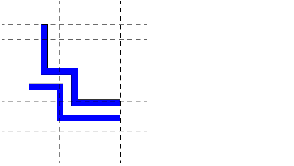
Track Patterns
Track patterns are objects which provide guide lines for routing and define the position and number of routing tracks. Routing tracks are used by gridded routers to determine preferred locations and directions for routes. The line segments of track patterns are arranged in uniformly-spaced orthogonal patterns extending across a base array. Corresponds to OpenAccess oaTrackPattern class.
Technology File Requirements for Track Patterns
The following must be defined in your technology file in order to create track patterns.
layerDefinitions(
techPurposes(
(track 229 trk)
...
)
techDisplays(
(layerNametrackpacketNamet t t t nil)
...
)
techLayerPurposePriorites(
(layerNametrack)
...
)
layerRules(
functions(
(layerName"metal"layerNumber)
...
)
To efficiently utilize the routing area, tracks should be created to consider the following design aspects:
Guidelines for Track Patterns
Tracks are drawn using the display attributes for LPP routingLayerName track.
Tracks patterns are uniformly-spaced orthogonal patterns extending across the base array. The tracks that make up the track pattern, provide guidelines for laying interconnect routes. Gridded routers place the center-line of each route collinear with an unused segment of a routing track. The VLS-L and VLS-XL allows you to interactively create routes that you can snap to routing tracks. Routing along tracks ensures routes are created without violating minimum spacing rules and are designed to maximize the utilization of available routing area.
Minimum Routing Pitch
Track spacing is determined from the routing pitch. The type of vias used will determine the pitch. The most common routing pitch is line-to-line, because it allows the minimum pitch between routes with a cross type via. A hammer head type via will require a via-to-line routing pitch. A larger pitch does not efficiently utilize the routing area, where as smaller pitch may result in low utilization of the routing area because the router will not be able to place vias next to a route. For more information, see “Determining the Track Spacing”.
Via Stacking
Routing layers using the same preferred direction can be placed on coincident tracks to allow for via stacking. If tracks can not be coincident, place the tracks at a ratio, for example, 1:2 or 2:3.
Preferred and Non-Preferred Routing Directions
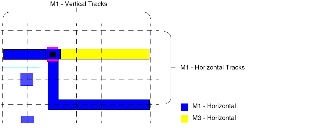
Tracks are created in both the preferred and non-preferred routing direction to allow for X Y locations where routes can be jogged and vias and pins can be placed and connected. Points where a horizontal track on one layer crosses over a vertical track on another layer are via locations where a vias can be placed. Most routing is done on the tracks aligned in the preferred direction. Small-distance jogs use tracks in the non-preferred direction.
Determining the Track Spacing
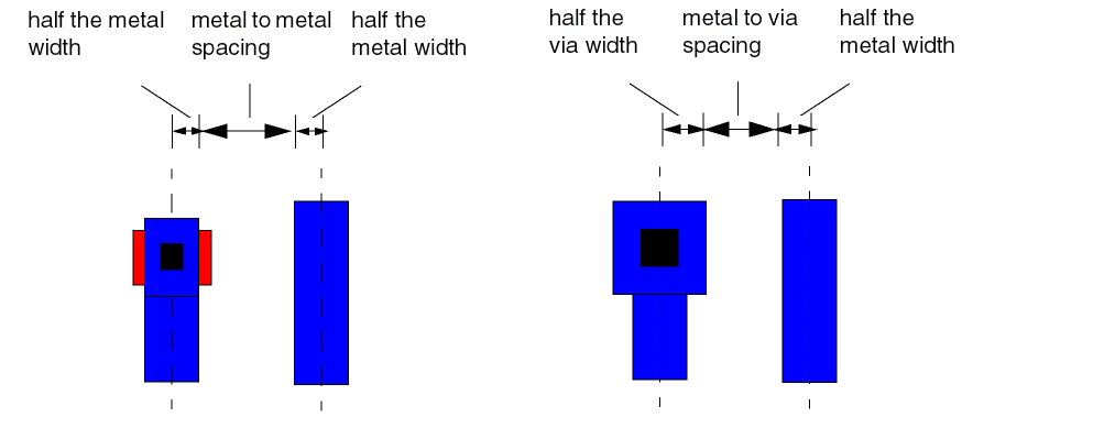
Determine the line-to-via track spacing (routing pitch) for each routing layer by adding:
half the metal width + metal to metal spacing + half the width of the metal
half the via width + metal to via spacing + half the width of the metal
For information about different types of routing pitches, see “Minimum Routing Pitch”.
Determining the Number of Tracks
You must determine the number of tracks needed for the width and the height of the cellview. Calculate the number of horizontal tracks by dividing the height of the design area by the
For information about accessing track pattern attributes, see
Markers
Markers are used to highlight design violations and the objects that are causing the violation which corresponds to OpenAccess oaMarker class.
Several types of markers are supported in the Virtuoso Studio design environment.
- fatal error: tool generated error. Can not be signed off, as it will always result in a non-functioning design or a design that can not be manufactured. Such error are generated usually from the process end (design rule) where the far/foundry does not want to allow sign-off.
- critical error: tool generated error. Usually requires a design review to sign- off.
- signed off critical error: error has been reviewed by the design team, and has been signed-off.
- error: error markers.
- signed off error: error has been signed-off.
- warning: warning markers.
- acknowledged warning: warning has been acknowledged by the designer.
- info: tool generated information.
- annotation: user generated information.
For information about accessing marker attributes, see
Steiner
A steiner is used to represent a logical object that facilitates, or is used to minimize net length of branching wires.

A steiner is a logical point representing the branching start or end point or points of a route or routes. Steiners can be associated with a particular layer and net, and also have geometrical attributes.
For information about accessing Steiner attributes, see
Layer Headers
In the Virtuoso environment, access to objects and shapes as they are grouped by layers is available at the API level through the objects, layerHeader and lppHeader.
A layerHeader objects holds information about a particular layer-purpose pair and the set of objects that use the layer purpose pair in a design database. The set of valid objects are; steiners, guides, blockages, and lppHeaders. The layerHeader provides direct access to these objects as they are grouped by layer.
A layerHeader is read only and can be bound or unbound. A bound layerHeader holds a valid technology database layer object. An unbound layerHeader only holds a layer number. layerHeader binding happens when layerHeader data is read in or a new layerHeader is created.
A layerHeader caches 3 union-ed bounding boxes for steiner, blockage and guide on the layer, one for each type of object. It also holds three lists of objects, one for each type for quick access.
The relationship of a layerHeader to objects is analogous to the relationship of an lppHeader to shapes. A layerHeader holds a collection of lppHeaders which contain the layer of the layerHeader. Therefore, a layerHeader provides indirect access to the shapes grouped by the lppHeaders.
For information about accessing cluster attributes, see
CDB and Preview Conventions for Identifying Objects
Controlling Display and Selection of Objects
Required Technology File Layers and Purposes for OpenAccess Objects
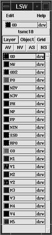
The Objects panel in the LSW lets you control visibility and selection of objects by turning on and off the relevant layer purpose pairs (LPPs). OpenAccess objects (marker, row, track pattern, boundaries, and blockages) are assigned to an LPP to control selectability and visibility. Your technology file must contain the LPP's which support OpenAccess objects, and your display.drf file must contain packets for these LPP's.
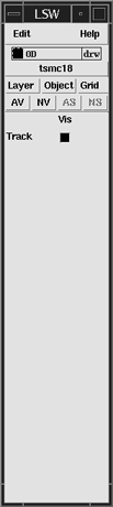
The Grid panel lets you control the visibility of track patterns.
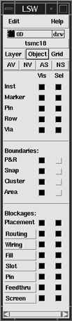
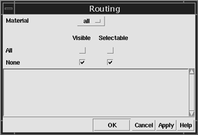
All blockage types, with the exception of placement, have forms which allow you to control the visibility and selectability on a layer by layer basis the blockages you create.
For more information, see Chapter 6, The Layer Selection Window (LSW) in the Virtuoso Layout Suite L User Guide.
Required Technology File Layers and Purposes for OpenAccess Objects
OpenAccess objects are assigned to layer purpose pairs (LPPs) to allow display and selection. The following table lists the layers and reserved purposes that allow you to control display and selection of OpenAccess objects. These layers and reserved purposes must be defined in the technology file. Corresponding packets are defined in the default.drf file located in the directory your_install_dir/share/cdssetup/dfII.
The default.drf file contains predefined attributes such as colors, line styles, and stipples for LPPs and is further organized into a set of predefined packets. When starting the software, the default.drf is loaded and any the customized display.drf file are merged with the default.drf. Because the files are merged in sequence, files loaded later in the sequence can redefine display packets, colors, line styles, and stipples specified in files loaded earlier. Layer attributes you have defined in a customized display.drf loaded after the default.drf will be respected. For example, the display packet for snap boundary is defined in a customized display.drf with a fill style of “solid”. This will overwrite the fill style of “outline” defined in the default.drf. In this case, all snap boundaries will be displayed with a solid fill obstructing the details of the cellview.
| Object | Layer | System-Reserved Purpose |
|---|---|---|
display.drf file. You can define packets for routing, fill, slot, pin, feedthru, and screen type of blockages. The blockages you draw will be based on the attributes defined in these packets, if they exist. For naming the packet, prefix the blockage type with the packet name used by the blockage layer and an underscore, as in M1Blockage_fill. The following is an example of a definition of a new packet in the display.drf file:( display M1Blockage_fill dots solid red red outlineStipple )
Unplaced Instances
Instances with the status of "unplaced" are not visible in the layout even though they are present in the design. The Instance Statistics section of the Design - Summary form displays the total number of unplaced instances.
See Placement Status for more information.
Shapes
Paths with Extensions
On CDB you can specify extension values for a path of any style before setting the style as variable (varExtendExtend). In the Virtuoso environment, you need to set the style to variable before you specify values for extensions.
For OpenAccess, there is a potential loss of data if you change the type from variable to anything else. When changed from variable, the original settings, including extension information, are lost. If you then set the path style back to variable, you need to reset the extensions as well. This is not necessary in CDB.
The C function, dbSetPathExt, behaves differently for CDB and the Virtuoso environment:
-
For CDB, the
dbSetPathExtfunction always returns TRUE, no matter what the path style is. When the path style is not variable, specified extension data is applied to the path in the database, but ignored by applications. -
On the Virtuoso environment,
dbSetPathExtreturns FALSE when the path style is not variable, and specified extension data is not applied to the path in the database.
The C function, dbGetPathExt, behaves differently for CDB and the Virtuoso environment:
-
For CDB, the
dbGetPathExtfunction always returns the path extensions, no matter how the path style is set. -
In the Virtuoso environment, the
dbGetPathExtfunction returns the path extension values when the style is variable but always returns zero for path extensions when the style is not variable.
Setting and querying the value of an extension differs for CDB and the Virtuoso Studio design environment:
- On CDB, you can set any value for extensions, independent of the style, and when you query an extension, the specified value is returned.
- In the Virtuoso environment, you cannot set a value for extensions unless the style is a variable. When you query an extension, the value returned is always zero (0.0) when the path style is not variable; when the style is variable, a query returns the extension value.
For example, for a path with the style truncate, setting and querying the beginning and ending extensions works as follows:
| Set, then query | Results for CDB | Results for Virtuoso Studio design environment |
|---|---|---|
Objects with Points
When a polygon or path is created, the Virtuoso environment removes any coincident and collinear points from the given point array to compress the amount of data used. CDB does not perform such checking. Therefore, data converted from CDB might have fewer points in OpenAccess. Although the bounding box will be the same, you need to review:
- Tests that compare or check the points or number of points
- Applications that rely on the ability to create collinear or coincident points
Retraced Segments in Polygons
Neither OpenAccess nor CDB allows self-intersecting polygons. However, for cases where a segment is created with points that are coincident with the points of an existing segment (when subsequent points retrace an existing segment), OpenAccess and CDB handle them as follows:
-
OpenAccess drops the last two points when they retrace an existing segment. If fewer than three points remain, the CDBA procedural interface issues a warning saying that there were not enough points to form a polygon.
- CDB does not check for retraced segments in polygons.
For example, the following statement attempts to create a five-point polygon, with the fourth segment overlapping (retracing) the third segment:
dbCreatePolygon( cv "metal1" list( 1:2 4:2 4:7 5:8 4:7 ))
OpenAccess truncates the last two points (5:8 4:7), and creates a polygon from the remaining three points. CDB creates a polygon that looks like a line, with the fourth segment retracing the third segment.
The following statement attempts to create a four-point polygon, with the third segment overlapping the second segment:
dbCreatePolygon( cv "metal1" list( 1:2 4:2 4:7 4:2 ))
OpenAccess truncates points 4:7 and 4:2, and the CDBA procedural interface issues a warning saying there are not enough points to form a polygon. CDB creates a polygon that looks like a line, with the third segment overlapping the second segment.
Zero-Area Rectangles
OpenAccess does not allow the creation of a rectangle with zero size. CDB allows the creation of zero-area rectangles. Both databases issue warnings:
-
OpenAccess: *WARNING* (
dbCreateRect) Invalid bounding-box for a rectangle - CDB: *WARNING* Rectangle being created has no area
For CDB, the GUI applications flag and correct zero-area rectangles before they get to the database. The only way to create zero-area rectangles in CDB is with db SKILL, itk or C functions. In OpenAccess, you cannot create zero-area rectangles.
Text Display Visibility
CDB and OpenAccess support different numbers of text display visibility attributes:
-
CDB supports three independent text display visibility attributes:
visible,nameVisible, andvalueVisible, each of which can betornil. - OpenAccess supports two independent visibility attributes:
As a result, CDB has eight possible visibility states, while OpenAccess has only six. Unfortunately, the existing API for setting individual text display visibility attributes can lead to transitions with particular sequences of flag settings that result in one of the following two states that are not supported in OpenAccess:
using state notation (visible, nameVisible, valueVisible).
In general, these are dubious states and are entered only as temporary states during a sequence of flag settings that are attempting to change the text display from one to another of the six OpenAccess-supported final states.
dbSetTextDisplayNameValueVisible( tdId nameVisble valueVisble )
has been added in C and SKILL to set both the nameVisible and valueVisible flags as a single operation, to prevent setting the text display visibility flags to the disallowed states. For a description of this function, see the dbSetTextDisplayNameValueVisible.
Warning messages are issued when an application tries to set the text display visibility flags to disallowed states under OpenAccess. Application developers need to know that illegal visibility states must be avoided, and the new warning messages help to identify these situations.
Bounding box for Net Expression Text Display Incorrect in OpenAccess
The size of the bounding box of a net expression text display for a terminal name attribute can be incorrect in OpenAccess. This is because OpenAccess does not evaluate net expressions from terminal name attributes.
CDB stores the terminal name and evaluates the net expression. OpenAccess stores the terminal name, but is unaware of the net expression. The size of net expression text display bounding boxes does not affect your design.
Unbound Text Displays
A cross-cellview text display object becomes unbound if it cannot be bound to its cross-cellview associate. In CDB, the unbound text display is deleted if the cellview containing the unbound text display is editable. In OpenAccess, the unbound text display is not deleted; instead, OpenAccess sets the text display text to
* Unbound *.
Arcs
Converting Start and Stop Angles for an Arc
In OpenAccess, the start and stop angles of an arc can be between 0 and 2PI. In CDB, start and stop angles can be between -PI and PI.
In the Virtuoso Studio design environment, querying an arc angle with dbGetArcAngle or dbGetArcRec returns angles between -PI and PI. Also when creating an arc with dbCreateArc, negative angles are accepted and the necessary adjustments are made.
However, if an application accesses the OpenAccess arc data directly, the application will need to make any necessary adjustments for start and stop angles that are between -PI and PI.
Selection of an Arcs
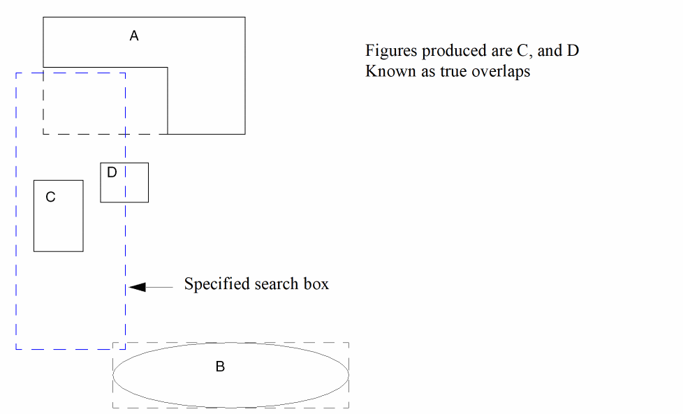
In the Virtuoso Studio design environment, the region query functionality has been changed to always support true overlaps of query regions for object geometries. See, Region Query Functions. Only objects whose geometry overlaps the specified region will be produced.
When selecting an arc, the arc must overlap the specified region in order to be selected.
Querying an Arc for Its Bounding Box
When you query an arc for its bounding box, the values returned in CDB and OpenAccess will usually differ.
When you create an arc with the dbCreateArc function, one of the arguments you must specify is the bounding box of the arc. An arc is defined by the intersection of two bounding boxes: the bounding box of the ellipse of which the arc is a part, and the bounding box specified to delimit the arc. The specified delimiting bounding box need not be the minimum bounding box; it just needs to intersect with the ellipse bounding box to define the beginning and end of the arc. Therefore, the specified delimiting bounding box might be larger than the minimum bounding box needed to define the arc.
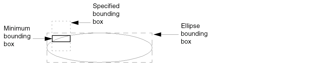
CDB saves both the ellipse and specified delimiting bounding boxes, and computes the start and stop angles from them. OpenAccess saves the ellipse bounding box and the start and stop angles, and computes the minimal bounding box that defines the arc.
In CDB, querying an arc for its bounding box, for example,
arc~>bBox
returns the value of the bounding box specified as an argument, which will probably be larger than the minimum bounding box required to define the arc.
In OpenAccess, querying an arc for its bounding box returns the exact bounding box of the arc, because OpenAccess calculates it from the ellipse bounding box and the start and stop angles.
Therefore, when you query an arc for its bounding box, the value returned by CDB and OpenAccess will probably be different.
Querying an Arc for Its Start and Stop Angles
The results of querying the start and stop angles of an arc might be slightly different for CDB and OpenAccess. This is because
- OpenAccess stores start and stop angles with double precision.
-
CDB stores start and sweep angles with single precision. In CDB, the sweep angle is calculated by subtracting the start angle from the stop angle:
Sweep Angle = ( stopAngle - startAngle )
So when you query the stop angle on CDB, the system calculates the result by adding the start angle and the stop angle.
Due to the difference between double and single precision, and the extra calculation for the stop angle performed by CDB, the following two query statements might return slightly different results for CDB and OpenAccess:
arc~>startAngle
arc~>stopAngle
Bounding Boxes of Labels and Text Displays
The bounding boxes of labels and text displays might be slightly different in OpenAccess and CDB. This is caused by a difference in how OpenAccess and CDB calculate their bounding boxes. OpenAccess rounds the values to the nearest database unit, where as CDB truncates them. The difference in the width and height of a label or text display could be off by 1 database unit (OpenAccess unit). Rounding to the nearest database unit is more accurate than truncating; CDB truncates.
If a label or test display is on the edge of a cellview, the difference described above might cause the cellview’s bounding box to be different. The result would be that the bounding boxes of the instances of this cellview would also be different.
Also, when you query an arc for its bounding box, the values returned in OpenAccess and CDB differ slightly.
Return to top