4
OpenAccess Technology Data Changes
This chapter describes the mapping between OpenAccess and Virtuoso for your technology data:
OpenAccess Data Models
With every new version release (data model revision), OpenAccess adds new kinds of data to the previous data model. The following table lists the prominent features associated with each data model revision.
Virtuoso Support for OpenAccess Data Models
This section describes the features of OpenAccess and The table below maps the Virtuoso support for OpenAccess data models in the various IC releases.
|
IC Virtuoso Release
|
OpenAccess Data Model
|
|
IC6.1
|
0, 1, 2, 3
|
|
IC6.1.1
|
0, 1, 2, 3
|
|
IC6.1.2
|
0, 1, 2, 3, 4
|
|
IC6.1.3
|
0, 1, 2, 3, 4
|
|
IC6.1.4
|
0, 1, 2, 3, 4
|
|
IC6.1.5
(ICADV12.1)
|
0, 1, 2, 3, 4
|
|
IC6.1.6
(ICADV12.2)
|
0, 1, 2, 3, 4, 5
|
|
IC6.1.7
(ICADV12.3)
|
0, 1, 2, 3, 4, 5
|
|
IC6.1.8
(ICADVM18.1)
|
0, 1, 2, 3, 4, 5, 6
|
Support for Incremental Technology Database
IC6.1.x releases see the introduction of incremental technology databases (ITDB). This method of handling technology data allows technology information from multiple sources, such as the foundry, an IP provider, or designer at different times in the design cycle. Applications can incrementally assemble technology information by creating references from one technology database to other technology databases. This will allow the appropriate design team the rights to manage only the specific section of technology information that is relevant to them.
In the following example, the LEF technology database, referenced by the Design Library, references two technology databases, the Foundry Variant technology database and the Standard Cell technology database. This means that the design constraints and process information in the referenced databases are applicable to the Design Library design. The Design libraries technology database is a derived technology database because it is, in effect, inheriting information from the technology databases that it references. Furthermore, both device technology databases reference the Foundry technology database, which references the default technology database. This chain of references is known as the technology database graph.
Each reference is created separately, and the technology database graph is created incrementally.
Setup
If incremental technology databases are not applicable to your design needs, your current technology database requires no setup or modification. The software, however, now handles all technology databases as incremental technology databases. Consequently, it will automatically remove system-reserved layers and purposes from your technology database and add a reference to cdsDefTechFile, the default technology database that defines system-reserved layers and purposes.
Conflict Checking
Since a technology library can inherit information from other technology libraries through an ordered set of references, conflicting objects are not allowed in a technology database graph. When a technology file is compiled, checks are done to determine if the objects with the same matching characteristics already exist within the database graph.
New Technology File Subsection
A technology file section has been added which lists the ordered technology libraries. For example,
controls(
   techParams( ... )
   viewTypeUnits( ... )
   mfgGridResolution( ... )
   refTechLibs(
      "StdCells"
      "PRtech"
      "Foundry"
   )
)
For information, see the Virtuoso Technology Data User Guide.
Constraint Support for 45/65 nm Process Rules
From IC6.1.2, Virtuoso leveraged the new OpenAccess data model 4 constraints to support the constraints for 45 nm and 65 nm processes for constructing correct layouts and to support the new LEF constructs.
Constraint Support for 32 nm Process Rules
From IC6.1.4, Virtuoso leveraged new constraints that have been added to OpenAccess data model 4 to support the 32 nm foundry design rules. Some existing constraints have also been enhanced to provide support for 32 nm processes. The new constraints and constraint options also support the new LEF 5.8 constructs. The new constraints are Cadence-specific and therefore, the prefix cdc is used for those constraints.
For writing a technology file that uses the new constraints, you need to start from a previous technology file from the same foundry, such as use 65 nm technology file to write a 45 nm technology file.
Support for Using Group Definitions
The oaGroupDef allows you to specify the definiton of a group. You can restrict the membership of the group by defining the object types that can be placed in the group as well as the databases in which the group can be created. For example, you can define a group that contains only oaNets.
Virtuoso leverages some of the OpenAccess built-in groups definitions for grouping nets. You can define the net groups using the Virtuoso Constraint Manager. You can create process constraints on these net groups using the Process Rule Editor.Using the Process Rule Editor, the process rules can be created either in the design or in the technology database.
ConstraintGroupDef
An oaConstraintGroupDef is a public object that specifies a definition for a constraint group. The definition contains a name, a type, a list of databases that the constraint group can be created in, a list of objects (by type) that the constraint applies to, a relationship type, and an indicator of whether or not there can be only one constraint group that uses this definition in any given database.
There are a set of built-in ConstraintGroupDefs with associated semantics:
-
oaImplicit -
oaDefault -
oaFoundry -
oaTaper -
oaInputTaper -
oaOutputTaper -
oaShielding -
oaTransReflexive -
oaReflexive -
oaInterChild -
oaUserDefined
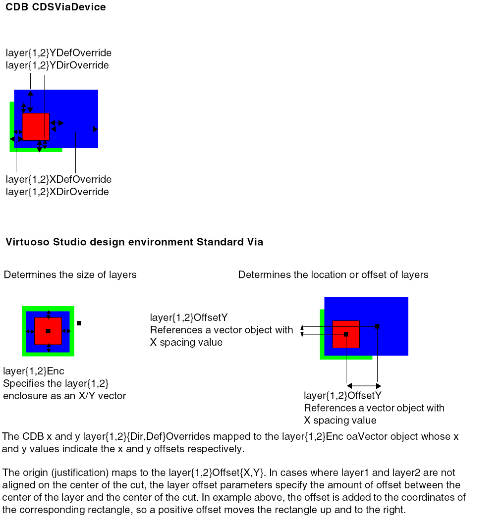
Support for Predefined Via Parameters
OpenAccess lets you store predefined parameterizations of oaStdVias and oaCustomVias. These predefined parameterizations of the via constraints are known as via variants. Thus, the oaViaVariant object represents a named pairing of an oaViaDef reference and a specified set of parameters. oaViaVariants can be stored in technology and design databases.
The ASCII technology file reader and writer support the oaViaVariants to preserve technology data integrity. Though Virtuoso supports these objects, it does not create them automatically.
Purpose-Aware Constraints
OpenAccess data model 4 supports purpose-aware constraints. This allows applications to limit the scope of a layer-based constraint to a specific set of purposes. These constraints are aimed for the fillOPC rules.
Reserved Purposes
In data model 4, OpenAccess has introduced built-in purpose types for matching a layer with a constraint. The oaFillopcPurposeType built-in purpose type specifies whether or not a fill shape requires OPC.
Support for New ITDB Constructs
processFamily
Foundries can set the this technology database attribute to ensure that technology databases in the same graph are from the same process family.
exclusiveLayers (layer attribute):
OpenAccess allows you to exclude layers by name from a graph of technology databases. This helps you prevent inadvertent references to incompatible layers in a graph of technology databases.
From IC6.1.2, you can create such constructs by explicitly adding them to your ASCII technology file and compiling it. These constructs are not mandatory. Virtuoso does not create these constructs automatically.
Constraint Parameters
There are new built-in oaConstraintParamTypes for which applications can create corresponding oaConstraintParams.
-
oacSpacingDirectionParamType -
oacCutDistanceConstraintParamType -
oacDistanceWithinConstraintParamType -
oacNoSharedEdgeConstraintParamType -
oacNotchLengthConstraintParamType -
oacNotchSpacingConstraintParamType -
oacNotchWidthConstraintParamType -
oacConnectivityTypeConstraintParamType -
oacPGNetConstraintParamType -
oacCenterToCenterConstraintParamType -
oacAreaConstraintParamType -
oacStackConstraintParamType -
oacExceptSamePGNetConstraintParamType -
oacNoSingleCutViaConstraintParamType
The following constraint parameter has been modified:
-
oacWidthLengthTableTypeConstraintParamType
This parameter is extended to accept a third integer value to designate that the constraint value stores the LEF SPACINGTABLE PARALLELRUNLENGTH TWOWIDTHS specification.
Huge String/Name Data
OpenAccess provides the ability to open very large databases containing over 4 GB of string data or over 2GB of string data from object names represented using oaName.
oaPartitions
OpenAccess provides the ability to access only the data that an application needs, improving both capacity and performance. Specifically, the oaPartition class lets an application organize data of a given data type into different partitions, which can then be loaded individually.
Huge oaPointArray Data
OpenAccess supports the ability to create more than 4GB of pointArray data on any one of the following design database objects: polygons, lines, paths, blockages, boundaries, and markers.
Huge oaAppProp Data
OpenAccess supports the ability to create more than 4GB of AppProp data in any OpenAccess database.
Moving Your Data to OpenAccess Data Model 4
When you open a database in IC6.1.2, it gets stamped as data model 4. For example, the use of the following constraints or features in IC6.1.2 triggers a data model 4 uprev on your data. When you save the design or technology database using these constraints or features, the data model 4 stamp will be attached to your database.
-
When a technology database that contains purpose-specific rules is loaded, the database is uprev’ed to data model 4.
For example,
minSpacing ( metal1 0.4) => will not trigger DM4
minSpacing ( ('metal1' 'fillOPC') 0.5) => will trigger DM4
minSpacing ( ('metal1' 'drawing') 0.4) => will trigger DM4 -
Any technology database referring to the
oaFillopcPurposeType purpose in an LPP-based rule or any design database containing shapes on this purpose are uprev’ed to data model 4 when loaded; the DFII reserved purpose number is uprev’ed to the OpenAccess system reserved purpose.
If a database created before data model 4 includes a user-defined purpose that uses a purpose number in the reserved range, and that database is loaded by newer OpenAccess shared libraries, the user-defined purposes in the reserved range are removed from the database. -
Use of the
'select operator in a derived layer construct of the ASCII technology file results in the corresponding technology database to be a data model 4 technology database.
For example,
techDerivedLayers(
  ; use purpose name allowed
    ( drv3   10003   (metal2  'select  drawing) )
  ; use purpose name allowed
    ( drv4   10004   (via     'select  label) )
  ; purpose number allowed
    ( drv5   10003   (metal2  'select  10) )
; techDerivedLayers
-
Setting the following attributes to anything different than the default value triggers data model 4 stamping for the design database.
pinId ~> type
layerBlockageID ~> allowPGNet
layerBlockageID ~> spacing
areaBlockageID ~> isSoft
areaHaloID ~> isSoft
Opening an IC6.1.1 Database
Whether or not a data model 4 feature is added to your database in IC6.1.2 and you attempt to open the technology or design database in IC6.1.1, you will receive one of the following messages based on the action you are trying to perform:
-
If you open a technology database that contains "do not open" DM4 features, you get the following warning message:
*WARNING* techGetObjTechFile: Tech database contains features defined in OpenAcess data model version 4, and cannot be opened by software that supports data model version 3
-
If you open a design database that contains "do not open" DM4 features, you get the following warning message:
*WARNING* dbOpenCellViewByType: Design database contains features defined in OpenAcess data model version 4, and cannot be opened by software that supports data model version 3
-
If you open a design database that contains "do not append" DM4 features, you get the following warning message:
*WARNING* dbOpenCellViewByType: Design database contains features defined in OpenAcess data model version 4, and cannot be opened for edit by software that only supports data model version 3. It can be opened for read.
Virtuoso Support of Technology File Constraints
Types of Constraint Groups
Foundry Constraint Group
Setup Constraint Group
Specialized Constraint Groups
Hard and Soft Constraints
Coincident Allowed Parameter
Constraint Group Properties
Constraint Group Semantics
Technology Database File Name
Technology File Updates Using Merge and Replace
Changes to Table Spacing Syntax
Translation of the resistancePerCut Property
In DFII on CDB, the technology file rules were implemented as hard foundry technology rules. In the Virtuoso Studio design environment, technology rules are replaced with technology constraints which are grouped into constraint groups.
Each constraint group contains subsections which are used to divide similar types of constraints into smaller sections. These sections closely correspond with the CDB rule sections. For example, the following CDB technology file class is mapped to the Virtuoso environment technology file as follows;
|
CDB Technology File
|
Virtuoso Studio design environment technology file
|
|
physicalRules(
spacingRules()
|
constraintGroups(
("foundry"
spacings()
|
For information about types of constraint groups, see Types of Constraint Groups.
Constraints and constraint groups (containers that hold constraints and references to constraint groups) can be defined in the technology file or are created when technology data is translated from an external application. Constraints that have been created by an external application (with proper name and definition) and translated into the Virtuoso environment are mapped to an appropriate constraint and constraint group in the technology file.
Whether or not a constraint group is applied to an object, depends on the application. Constraints are obeyed only in the event an application is designed to adhere to them. The Virtuoso application support is based on the applicable constraint group (and thus the contained constraints) and of the constraints in that group, which are designated to be enforced or obeyed by the application.
In the diagram below, minArea is defined as single layer spacing constraint in the Virtuoso technology file and is mapped to the constraint type oacMinArea. The LEF technology data {AREA minArea} also maps to the constraint type oacMinArea. Using the predefined name and explicit definition allows interoperability between tools.
User Defined Constraints
CDB rules translated to the Virtuoso environment can be added to two types of sections within a constraint group.
-
CDB rules that map correctly to the Virtuoso environment constraint definitions and are interoperable with other applications on OpenAccess.
-
User defined constraints which are CDB rules that have a unique name and can not be mapped to an OpenAccess constraint. User defined constraints are only accessible to Virtuoso applications and are not interoperable with other tools. This includes layer purpose pair (LPP) based constraints. Technology file constraints that are defined for LPPs are stored as a private extensions and are only available for Virtuoso applications.
For information about how rules are mapped, see Mapping CDB Physical Technology File Rules to OpenAccess Constraints.
OpenAccess constraints support an implicit order of precedence. User defined constraints do not support an order of precedence. Because of this, user defined constraints are grouped below all OpenAccess constraints that do require order.
For example, a CDB technology file containing spacingRules, orderedSpacingRules, and tableSpacingRules, when translated and dumped, could contain six sections,
-
user defined
spacingRules -
OpenAccess
spacingRules -
user defined
orderedSpacingRules -
OpenAccess
orderedSpacingRules -
user defined
tableSpacingRules -
OpenAccess
tableSpacingRules
The user defined spacing rule, minMosWidth, is defined as:
constraintGroups(
( "foundry"
;physical constraints
   spacings(
   ( minSpacing tx_layer g_value )
   ) ;spacings
   spacings(
   ( minMosWidth tx_layer g_value )
   ) ;spacings
) ;foundry
) ;constraintGroups
The value of a user defined constraint is applied as a string. The interpretation of the string is handled by individual applications.
|
Virtuoso Studio design environment ASCII Technology File Definition:
t_userConstraint lt_layer1 [lt_layer2] t_value )
Example:
(userConstraint metal1 "myValue")
|
|
DFII on CDB ASCII Technology File Definition:
NA
|
|
OpenAccess Constraint:
Value type: oaStringValue
|
Types of Constraint Groups
There are different types of constraint groups which are supported: foundry and setup constraint groups. Constraint groups are applied to the design associated with the attached technology library.
Foundry Constraint Group
The foundry constraint group consists of the set of technology constraints that must always be satisfied. These constraints are implicitly applied to all designs that are associated with a technology database containing this set of constraints. For example:
constraintGroups(
   ( "foundry"
The name of the hard foundry constraint group defined in the ASCII technology file is foundry. The name foundry is only defined in the Virtuoso environment. The OpenAccess foundry constraint group is not associated with a specific name.
Setup Constraint Group
Setup constraint groups are used by the XL layout editor and the chip assembly router. The default names of the setup constraint groups are:
-
virtuosoDefaultExtractorSetup: XL layout editor -
virtuosoDefaultSetup: chip assembly router.
The virtuosoDefaultExtractorSetup constraint group lists the valid layers to be used for XL layout editor connectivity extraction and the layers to be used by the Create Wire command within the XL layout editor.
Setup constraint groups can be created using any name and can be selected from the options form of the corresponding application.
Specialized Constraint Groups
The following user-defined constraint groups are created by OpenAccess LEF and DEF translators:
-
LEFDefaultRouteSpec: Stores routing information, such as information about layers and vias -
LEFSpecialRouteSpec: Stores information about power routing vias
The specialized constraint groups can be stored in either technology or design database. If stored in a technology database, the constraints apply across any design that is associated with that technology. If stored in the design database, the constraints apply only to that particular design. Design-specific constraints take precedence over constraints in the technology database.
A single technology can have only one LEFDefaultRouteSpec and one LEFSpecialRouteSpec. However, each technology in a graph of technology databases can have its own set of these constraint groups. In addition, a design can have its own LEFDefaultRouteSpec and LEFSpecialRouteSpec constraint group. Therefore, an application can have multiple LEFDefaultRouteSpecs and multiple LEFSpecialRouteSpecs in a graph of referenced technology databases. An application creates overriding constraints in the more derived technology.
Older databases do not allow multiple constraint groups named LEFDefaultRouteSpec because they conflict by name. In OpenAccess data model 4, by using the constraint group definition, a graph can have multiple constraint groups of these types as long as the constraint groups names are unique in the graph.
For information about how OpenAccess LEF and DEF translators map constructs into LEFDefaultRouteSpec and LEFSpecialRouteSpec, see Design Data and Technology Data Preparation in the Mixed Signal (MS) Interoperability Guide.
Member Constraint Group
A constraint group can be created as a member of another constraint group. When multiple member constraint groups are specified, their order of precedence is from top to bottom; that is, the first member constraint group specified has the highest precedence, and the last has the lowest.
Built-In Constraint Group Types
Most of the built-in constraint group types are for the design database only. However, some of them can be specified in the technology database as well.
|
Virtuoso Studio design environment ASCII Technology File Definition:
constraintGroups(
; name [override] [type]
  ( "group" [t | nil] [nil | "taper" | "inputTaper" | "outputTaper"]
  ...
  ) ; group
) ;constraintGroups
|
|
DFII on CDB ASCII Technology File Definition:
NA
|
|
OpenAccess Constraint:
Class: oaTaper, oaInputTaper, oaOutputTaper
Constraint type: oaConstraintGroupTypeEnum
|
|
LEF Syntax:
NA
|
|
Hard and Soft Constraints
In Virtuoso, soft constraints saved to Virtuoso or translated to Virtuoso are preserved in the technology file. However, Virtuoso applications do not support soft constraints. The hard and soft indicators are as follows:
( t_constraint [lt_layers] g_value 'hard )
( t_constraint [lt_layers] g_value 'soft )
Coincident Allowed Parameter
The coincident allowed parameter, which can be specified for several constraints, is defined using the 'coincidentAllowed symbol. It cannot be specified for user-defined or layer-purpose pair constraints.
( t_constraint [lt_layers] g_value 'coincidentAllowed 'hard)
( t_constraint [lt_layers] g_value 'soft 'coincidentAllowed)
Constraint Group Properties
In the Virtuoso environment, properties can be associated with a constraint group. The following is an example of a property applied to a constraint group:
constraintGroups(
;( group
( "constraintGroupName"
...
   properties(
   ( t_propName g_value )
   ); properties
) ;constraintGroupName
); constraintGroups
Constraint Group Semantics
Constraint groups follow the precedence semantic as per which, the first hard constraint found in the constraint group must be satisfied. If a soft constraint is encountered and not satisfied, the search for constraint continues until either a constraint that can be satisfied is found or a hard constraint that cannot be satisfied is found.
To handle the more complex rules of 45/65 nm processes where constraints are specified as either a series of circumstances in which a given constraint applies or a set of exception conditions in which the constraint does not apply, the following constraint group semantics are used:
-
AND: This operator specifies that all constraints within the same constraint group must be satisfied.
-
OR: This operator specifies that only one of constraints within the same constraint group must be satisfied.
The precedence semantic is the default semantic followed by constraint groups.
|
Virtuoso Studio design environment ASCII Technology File Definition:
constraintGroups(
; name [override] [type] [semantic]
  ( "group" [t | nil] [nil] ['and | 'or | 'precedence]
  ...
  ) ; group
) ;constraintGroups
|
|
OpenAccess Constraint:
Semantic-type attribute on constraint group: enum
|
For example, the following LEF representation of minimum protrusion number of cuts constraint for layer VIA 1:
MINIMUMCUT 2 WIDTH 0.419 LENGTH 0.419 WITHIN 5.000;
MINIMUMCUT 4 WIDTH 0.979 LENGTH 0.979 WITHIN 6.000;
would map to the following constraint group using the AND operator:
constraintGroups(
  ( "myAndConstraintGroup" nil nil 'and
     spacings(
     ( minProtrusionNumCut VIA1 'distance 5.000 'width 0.419 'length 0.419 2 )
     ( minProtrusionNumCut VIA1 'distance 6.000 'width 0.979 'length 0.979 4 )
     ) ;spacings
  ) ;myAndConstraintGroup
) ;constraintGroups
Technology Database File Name
The name of the technology database file has changed from techfile.cds to tech.db; however, do not hard code the filename. Applications that use a hard-coded technology filename should no longer do so. Instead, if you require the technology filename, retrieve it as follows:
-
For SKILL, use the new SKILL function
techGetDefaultTechName -
For C and C++, use the
# define techcDefaultTechFileName constant
Technology File Updates Using Merge and Replace
The following describes the behavior of loading a technology library with an ASCII technology file using the Merge and Replace options on the Load Technology File form.
-
Using Merge does not manipulate constraint groups.
When updating a technology library using the Merge option, existing constraint groups that are not referenced in ASCII version of the technology file are not manipulated. -
Using Replace removes constraint groups.
When updating a technology library using the Replace option, existing constraint groups that are not referenced in ASCII version of the technology file are removed.
For example, if the existing technology file contains constraint groups A, B, and C, and the ASCII version contains A’ and D (A’ being a modified constraint group) the results of updating would be:
-
Using the Merge option would result in a technology library containing constraint groups A’, B, C and D.
-
Using the Replace option would result in a technology library containing constraint groups A’ and D.
When updating the technology library using both Merge and Replace option,
-
new constraint groups referenced in ASCII version of the technology file are added.
-
same name constraint groups in the existing technology file are replaced with the ASCII version of the technology file.
Changes to Table Spacing Syntax
Virtuoso Environment Syntax
In the spacingTables() syntax, each table index definition is given by:
l_index1Definitions is a list defining the name, predefined index values, and user defined match function for the first table dimension. The format of the list is as follows:
( [nt_indexName] [(lg_indexValue...)] [t_userMatchFunction] )
-
where
nt_indexName is the name of the first dimension of a two dimensional table or the only dimension of a one dimensional table. Valid values: Any number or string. -
The
g_indexValue is a list of predefined indexes, specifying the indexes that can be used in the table. Valid values: Any number or string. -
The
t_userMatchFunction is the name of a user-defined match function. Valid values: Any string.
CDB Syntax
In CDB, entries in the table are defined in the following way:
the l_table is a list defining the table entries, in the following format:
( g_index1 [t_matchType1] [ g_index2 [t_matchType2] ] g_value ... )
-
where
g_index1 is the first index in a two dimensional table or the only index in a one dimensional table. Valid values: Any number, string, or list. -
The
t_matchType1 is the match type to use for index1. Valid values: One of the following: < , <=, ==, >=, >, userMatchFunction or nil where userMatchFunction is a user-defined match function. Default: ==. -
The
g_index2 is the second index in a two dimensional table. Valid values: Any number, string, or list. -
t_matchType2 is the match type to use for index2. Valid values: One of the following: <, <=, ==, >=, >, t_userMatchFunction or nil where userMatchFunction is a user-defined match function Default: ==. -
g_value is the value to use when the application finds a match to the index or pair of indexes during table lookup. Valid values: Any number or string.
In the Virtuoso environment technology file of any table, a unified "match function” is defined, either ">=" (">") or "<=" (<), depending on the semantic defined for the constraint the table is representing, except for on the index boundaries (lowest or highest index value) which you may specify differently. The indexes of the table are sorted in ascending order.
Currently, the match function, if it is defined, is ignored. All tables are predefined with ">=" look up. When the technology file is translated from CDB to Virtuoso environment, the translation does not convert the match function since this is not supported. During translation, the table is populated by the correct values from the CDB table taking into consideration any match functions which may be defined.
Translation of the resistancePerCut Property
If the property resistancePerCut exists on cellview, the value of the property is translated to resistancePerCut of the via definition.
If the property res exists on cellview, the value is translated to resistancePerCut of the via definition as the value of property multiplied by the number of cuts.
If the electrical rule resistancePerCut exists on the via layer, the value is translated to resistancePerCut of the via definition.
Conversion of Technology File controls Class
Layers
|
Virtuoso Studio design environment ASCII Technology File Definition:
constraintGroups(
( "virtuosoDefaultSetup"
   interconnect(
   (validLayers (tx_layer)... )
   ) ;interconnect
) ;virtuosoDefaultSetup
) ;constraintGroups
layerRules(
   functions(
      ( tx_layer tx_material g_maskNumber)
   ); functions
);layerRules
Layer purposes in iccLayers() are ignored.
|
|
DFII on CDB ASCII Technology File Definition:
iccLayers = list(
   list(lt_layer t_function t_direction f_width f_spacing [g_ref [g_translate]])
   [list(...)]...
)
|
|
OpenAccess Constraint:
Class: oaSimpleConstraint
Constraint type: oacValidRoutingLayers
Value type: oaLayerArrayValue
Class: oaConstraintGroup, virtuosoDefaultSetup()
|
Vias
|
Virtuoso Studio design environment ASCII Technology File Definition:
constraintGroups(
( "virtuosoDefaultSetup"
   interconnect(
   (validVias (tx_layer)... )
   ) ;interconnect
) ;virtuosoDefaultSetup
) ;constraintGroups
For cdsViaDevices: standardViaDefs()
viaDefs(
standardViaDefs(
   ( t_viaDefName tx_layer1 tx_layer2
      ( t_cutLayer n_cutWidth n_cutHeight [n_resistancePerCut] )
      ( x_cutRows x_cutCol ( l_cutSpace ) )
       l_layer1Enc ) ( l_layer2Enc ) ( l_layer1Offset )
      ( l_layer2Offset ) ( l_origOffset )
      [tx_implant1 (l_implant1Enc) [tx_implant2 (l_implant2Enc]]
   )
) ;standardViaDefs
) ;viaDefs
All other vias: customViaDefs()
viaDefs(
   customViaDefs(
       ( t_viaDefName t_libName t_cellName t_viewName
      tx_layer1 tx_layer2 [n_resistancePerCut] )
   ) ;customViaDefs
) ;viaDefs
For more information about mapping CDB vias, see Mapping of CDB Devices.
|
|
DFII on CDB ASCII Technology File Definition:
iccVias= list(
   list(
       list([list(t_libName t_cellName t_viewName)] |
       t_pseudoViaName list(lt_layer ....)
       [g_translate])
           [list(...)]...
)
|
|
OpenAccess Constraint:
Class: oaSimpleConstraint
Constraint type: oacValidRoutingVias
Value type: oaLayerArrayValue
Class: oaConstraintGroup, virtuosoDefaultSetup()
|
DBUPerUU Stored in the Technology File
Unlike CDB, OpenAccess provides a single location for database units per user unit (DBUPerUU) and user unit information (userUnit) stored in the technology file. The following is an example of the ASCII technology file syntax.
controls(
   viewTypeUnits(
   ( maskLayout          "micron"        2000            )
   ( schematic           "inch"          160             )
   ( schematicSymbol     "inch"          160             )
   ( netlist             "inch"          160             )
   )
)
When migrating data from CDB to the Virtuoso environment, the values for user units (userUnits) and DBUPerUU are obtained from various locations and consolidated at a single location in the technology file.
The value of 0.0 is accepted in the technology file. If the value of 0.0 is unintentionally set in the technology file, the bbox of a new cellview and the initial window zoom level would be infinite. Also, the technology file API (see below) would return a value of (NAN:NAN:NAN:NAN).
DBUPerUU Access
The APIs listed below are provided to access DBUPerUU and userUnit information in order to meet the new model. These new APIs are implemented only for OpenAccess-based technology file APIs.
techGetDBUPerUU(d_techFileId t_cvType)
techSetDBUPerUU(d_techFileId t_cvType f_dbuperuu)
techGetUserUnit(d_techFileId t_cvType)
techSetUserUnit(d_techFileId t_cvType t_userUnit)
Using lib~>DBUPerUU or lib~>userUnits will report a warning. Also, lib~>prop will not return DBUPerUU and userUnits as properties. Any SKILL procedures depending on these calls should be modified.
For example, if the original SKILL code set the dbu/uu as
lib~>DBUPerUU~>maskLayout = 2000.0
the code based on OpenAccess should be
techSetDBUPerUU(techGetTechFile(lib) "maskLayout" 2000.0)
Manufacturing Grid
In CDB, the manufacturing grid was stored in the physicalRules class. In Virtuoso, the manufacturing grid is stored in the controls section of the technology file.
Manufacturing Resolution
|
Virtuoso Studio design environment ASCII Technology File Definition:
controls(
   mfgGridResolution( g_resolution )
) ;controls
|
|
DFII on CDB ASCII Technology File Definition:
physicalRules(
   mfgGridResolution( g_resolution )
) ;physicalRules
|
|
OpenAccess Constraint:
Class: oaTech
::getDefaultManufacturingGrid()
Class: oaPhysicalLayer
::resetManufacturingGrid()
|
Conversion of Technology File layerDefinitions Class
Technology File Changes for Layer Purposes
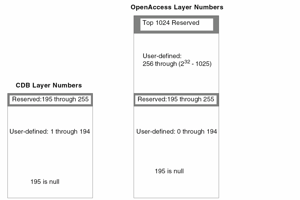
The purpose 0 is “unknown” (reserved).
For OpenAccess, the number of purposes has been increased as follows:
-
You can define purposes numbered 1 through 128.
-
If you want to define more purposes, you need to define purposes between 256 through 232 - 65535.
If you need to define more than 128 purposes, start with purpose number 256 and increment it by one to avoid conflict with purpose numbers at the high end of the range that are reserved by Cadence for future system use.
Virtuoso Studio design environment Technology File Reserved Purpose Types
The following table lists the Virtuoso reserved purposes that support control of display and selection of specific objects. The LPPs for the objects must be present in the technology file and the corresponding packets must be present in the display.drf file. Highlighted system reserved purposes are new in the Virtuoso Studio design environment.
|
System Reserve Purpose
|
Purpose #
|
Abbreviation
|
|
redundant
|
-8
|
|
|
customFill
|
-12
|
|
|
gapFill
|
-7
|
|
|
annotation
|
-6
|
|
|
OPCAntiSerif
|
-5
|
|
|
OPCSerif
|
-4
|
|
|
slot
|
-3
|
|
|
fill
|
-2
|
fil
|
|
fillOPC
|
-11
|
fio
|
|
drawing
|
-1
|
drw
|
|
fatal
|
223
|
fat
|
|
critical
|
224
|
crt
|
|
soCritical
|
225
|
scr
|
|
soError
|
226
|
ser
|
|
ackWarn
|
227
|
ack
|
|
info
|
228
|
inf
|
|
track
|
229
|
trk
|
|
blockage
|
230
|
blk
|
|
grid
|
231
|
grd
|
|
warning
|
234
|
wng
|
|
tool1
|
235
|
tl1
|
|
tool0
|
236
|
tl0
|
|
label
|
237
|
lbl
|
|
flight
|
238
|
flt
|
|
error
|
239
|
err
|
|
annotate
|
240
|
ant
|
|
drawing1
|
241
|
dr1
|
|
drawing2
|
242
|
dr2
|
|
drawing3
|
243
|
dr3
|
|
drawing4
|
244
|
dr4
|
|
drawing5
|
245
|
dr5
|
|
drawing6
|
246
|
dr6
|
|
drawing7
|
247
|
dr7
|
|
drawing8
|
248
|
dr8
|
|
drawing9
|
249
|
dr9
|
|
boundary
|
250
|
bnd
|
|
pin
|
251
|
pin
|
|
net
|
253
|
net
|
|
cell
|
254
|
cel
|
|
all
|
255
|
all
|
Changing the Number of Characters for LSW Purpose Abbreviation
To change the display from 3 to 2 characters for the purpose abbreviation in the LSW, use the layout environment variable lswLPIconPurposeLength. For example,
envSetVal("layout" "lswLPIconPurposeLength" 'int 2)
LEF In Changes for Valid Layer Purposes
When translating data into the Virtuoso environment using LEF In, the following layer purposes are by default not valid, meaning they do not appear in the LSW. These purposes are used for display of objects only and the LPPs will not be available for shape drawing from the Layer panel of the LSW. Control selection and display of objects through the Object panel of the LSW.
net
pin
slot
fill
gapFill
blockage
boundary
The lefin option -pinPurp allows you to specify a specific purpose for pins, such as "pin", when translating data. By default, pins are created on the purpose "drawing". You can specify any purpose name. If the purpose does not exist in the technology library then lefin will create the purpose and add the name to the technology file. The purpose chosen as the pin purpose will be valid by default. This change only effects technology files newly created by LEF In.
OpenAccess Constants for Reserved Purposes
The following table shows the Cadence-defined constants for reserved purposes for the OpenAccess database. These predefined purposes are always available, and may not be changed nor removed. The Constant for Purpose Name always has the data type of string, while the Constant for Purpose Number has its data type determined by the typedef, dbPurpose.
|
Purpose Name
Constant for Purpose Name
Constant for Purpose Number
Value
|
Description
|
|
redundant
oacPurposeRedundant
oavPurposeNumberRedundant
232 - 8
|
The redundant purpose is used to flag specific objects that have been placed more than once, such as double vias on a route.
|
|
gapFill
oacPurposeGapFill
oavPurposeNumberGapFill
232 - 7
|
Elements marked with the gapFill purpose are used to fill large open areas of a mask to increase planarization of the layer during manufacturing. These elements are not part of any electrical network on the chip.
|
|
annotation
oacPurposeAnnotation
oavPurposeNumberOPCAntiSerif
232 - 6
|
Used for chip annotation, such as labels and logos
|
|
OPCAntiSerif
oacPurposeOPCAntiSerif
oavPurposeNumberOPCAntiSerif
232 - 5
|
Identifies data created for optical proximity correction, in which data is removed from drawn masks.
|
|
OPCSerif
oacPurposeOPCSerif
oavPurposeNumberOPCSerif
232 - 4
|
Identifies data created by optical proximity correction, in which data is added to drawn masks.
|
|
slot
oacPurposeSlot
oavPurposeNumberSlot
232 - 3
|
Identifies shapes to process for slotting modification to avoid errors during the manufacturing process.
|
|
fill
oacPurposeFill
oavPurposeNumberDrawing
232 - 2
|
Identifies shapes as fill shapes to satisfy the requirement that a certain percentage of your chip be made from a specific material.
|
|
drawing
oacPurposeDrawing
oavPurposeNumberDrawing
232 - 1
|
Default purpose used for the creation of objects.
|
Different Purpose and Layer Numbers Values
In CDB, the drawing purpose is represented by the number 252. In OpenAccess the drawing purpose is represented by 232 - 1, which in hexadecimal is the number 0xffffffff.
The range of values for both purpose and layer numbers is much higher for OpenAccess than for CDB, due to the larger number of bits available. And for OpenAccess, the values of some reserved purpose numbers are assigned differently than for CDB.
-
CDB uses 8-bit unsigned characters to represent positive numbers, in the range 0 through 255, which can also be stated as 0 through 28 - 1.
-
OpenAccess uses 32-bit unsigned integers to represent positive numbers, in the range of 0 through 232 - 1. Large numbers in this range are represented in hexadecimal.
Purpose and Layers Numbers Can Appear as Negative Numbers.
SKILL can handle only signed numbers; therefore, in OpenAccess, large, unsigned numbers appear as negative numbers in SKILL, and when printed out by SKILL to ASCII.
For example, in OpenAccess, the drawing purpose is represented by 232 - 1, which in hexadecimal is the number 0xffffffff.
In C or C++, the unsigned number 0xffffffff is available “as is”, however, in SKILL and ASCII produced by SKILL, it is not. In SKILL or ASCII, the number 0xffffffff is treated as signed and appears as -1, a negative number.
Updating User-Defined Purpose Names
Updating User Defined Purposes and Hard Coded Values
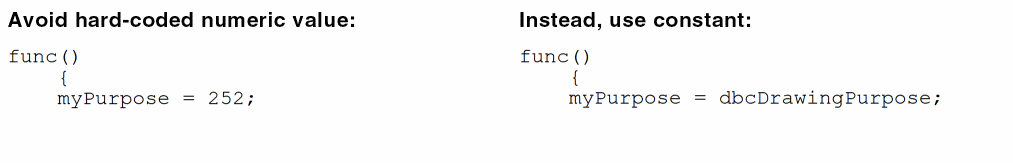
You will need to update your code if your code contains hard-coded purpose number such as 252 to represent the drawing purpose. If your code contains user defined purposes that conflict with OpenAccess purposes or CDB-specific hard-coded purpose numbers, your code will not work correctly with the OpenAccess database until you replace them.
Ideally, you should replace hard-coded numbers with their Cadence-defined names; for example, replace the number 252 with the string name, drawing. It is less desirable to replace CDB-specific hard-coded numbers with OpenAccess-specific hard-coded numbers, since hard-coded numbers are likely to require more maintenance in the future.
However, if you must use the purpose number instead of the purpose name in OpenAccess, you will have to use the negative number, which in SKILL, is equivalent to the large, unsigned number in OpenAccess. For example, you would have to use -1 for the drawing purpose.
In C and C++ code replace user defined purposes that conflict with OpenAccess purposes or hard coded values or with the OpenAccess-specific constant for the purpose name or purpose number. See OpenAccess Constants for Reserved Purposes.
Reload your code before you translate your data, especially if it includes SKILL-based Pcells.
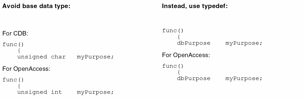
Updating Data Type Definitions
You will need to update your code if your code contains CDB specific base data type definitions for purpose (such as unsigned char) instead of a Cadence-defined typedef (such as techLayerNum)
In SKILL, there are no Cadence-defined constants for purpose and layer numbers; nor are there typedefs. Typedefs are not needed, because SKILL automatically determines the data type for purpose and layer numbers, so no change is needed to SKILL code for data types
For C and C++ Code, Use Cadence-Defined Constants and typedefs
Cadence-Defined Constants
The drawing purpose is the only Cadence-defined purpose name that is common to both CDB and OpenAccess; however, it is defined by different purpose numbers. To make your C and C++ code database independent for the drawing purpose, use the following Cadence-defined constants for the drawing purpose:
-
The database constant is
dbcDrawingPurpose -
The technology file constant is
techDrawingPurpose
These two constants are common to CDB and OpenAccess; using them helps your code run on both databases, and makes moving from CDB to OpenAccess easier.
In addition to drawing, CDB has numerous other Cadence-defined constants for purpose numbers, while OpenAccess has only a few. There are new Cadence-defined constants for the new OpenAccess reserved purpose names, but they are specific to the OpenAccess database, as those purposes are not defined by Cadence for CDB.
Cadence-defined constants for the values of database purpose numbers appear as hash define (#define) statements that look like this:
For CDB:
|
#define
|
dbcDrawingPurpose
|
252
|
For OpenAccess:
|
#define
|
dbcDrawingPurpose
|
0xffffffffu
|
For the location of the files containing the Cadence-defined constants for both CDB and OpenAccess, see “Location of Cadence-defined Constants and typedefs”.
Example of Constant for a Purpose Number
For example, for the drawing purpose in CDB, the purpose number is represented by the integer constant 252. But instead of setting the drawing purpose to a specific number for either CDB or OpenAccess, you should set it to the Cadence-defined constant for the drawing purpose, which is dbcDrawingPurpose or techDrawingPurpose, as shown below. Then your code will work with both databases.
For information about the Cadence-defined constants for purposes reserved by OpenAccess, see “OpenAccess Constants for Reserved Purposes”.
Cadence-Defined Constants typedefs
Cadence provides predefined typedefs that let you indicate the data type for the variables you declare for purpose and layer numbers. These typedefs are common to both CDB and OpenAccess. To make your C and C++ code database independent for the data types of your variables for purposes and layers, use the following Cadence-defined typedefs:
-
The database typedefs are
dbPurpose and dbLayer. -
The technology file typedefs are
techPurpose and techLayerNum.
The Cadence-defined typedef statements for database purpose and layer numbers look like this:
For CDB:
|
typedef unsigned char
|
dbPurpose;
|
|
typedef unsigned char
|
dbLayer;
|
For OpenAccess:
|
typedef unsigned int
|
dbPurpose;
|
|
typedef unsigned int
|
dbLayer;
|
And for technology file purpose and layer numbers, they look like this:
For CDB:
|
typedef unsigned char
|
techPurpose;
|
|
typedef unsigned char
|
techLayerNum;
|
For OpenAccess:
|
typedef unsigned int
|
techPurpose;
|
|
typedef unsigned int
|
techLayerNum;
|
For the location of the files containing the Cadence-defined typedefs for variables for both CDB and OpenAccess, see “Location of Cadence-defined Constants and typedefs”.
In CDB, the data type for purpose number is unsigned char. But instead of using the base data type to declare variables, you should use the Cadence-defined typedefs; then your code will work with both CDB and OpenAccess.
Example of typedef for Purpose Numbers
For example, you need to declare a variable to contain the value of a purpose, such as drawing. The Cadence-defined typedef for purpose is dbPurpose. For purpose numbers, the base data type for CDB is unsigned char, while for OpenAccess, it is unsigned int. Instead of using the database-specific base data type, use dbPurpose, as shown below:
You do not even need to know what the data type of your variable for purpose is; the Cadence system will determine which database is being used and assign the appropriate data type to dbPurpose.
Location of Cadence-defined Constants and typedefs
For both CDB and OpenAccess, you can view the Cadence-defined constants and typedefs in the following locations:
Technology File Changes for Layers
-
User-defined layers are 0 through 194 and 256 through 232 - 1025.
-
Cadence reserves the layers numbered 196 through 255 for system use, with layer 195 as the “null” layer and layers numbered 232 - 1024 through 232 - 1.
System Reserve Layers
When loading an ASCII technology file that contains user defined layers or obsolete layers within the reserved layer range, warning messages are issued and the layers are not created. For example, the following layers are obsolete as of the 4.4 release. If any of these layers still exist in your technology file you must remove them and re-load the technology file.
( winActiveBanner        240     winActi     )
( winAttentionText       241     winAtte     )
( winBackground          242     winBack     )
( winBorder              243     winBord     )
( winBottomShadow        244     winBott     )
( winButton              245     winButt     )
( winError               246     winErro     )
( winForeground          247     winFore     )
( winInactiveBanner      248     winInac     )
( winText                249     winText     )
( winTopShadow           250     winTopS     )
To remove obsolete layers or layers that are incorrectly defined in the reserved layer range, do the following.
-
In the CDB database, dump the ASCII technology file.
-
Using a text editor, find and delete incorrectly defined layers.
-
Load the ASCII technology file back into the technology library in Replace mode.
-
Translate the library to the Virtuoso environment.
Virtuoso Environment Layer Purpose Pairs Support
In the Virtuoso environment technology file it is possible to define technology rules for layer purpose pairs (LPP). For example, if you have a purpose named highPower for metal1 then you could define a different minimum width constraint for metal1 shapes with the highPower purpose from the minimum width for the metal1 layer shapes with no purpose specified.
OpenAccess rules/constraints are only applicable to layers, not layer purpose pairs. Currently in the Virtuoso environment, any technology rule which is defined for a layer purpose pair is stored as a private extension and is available for Virtuoso applications. However, the private extension is not visible outside Virtuoso applications.
Layer purpose constraints are supported in any constraint group. Although it is not permitted to define the same layer purpose pair constraint within a constraint group.
Technology File and LPP SKILL Attribute Changes
Technology File Attributes Name Changes
The names of the following technology attributes are different for CDB and the Virtuoso environment.
|
Technology File Attributes
|
CDB return value
|
Virtuoso return value
|
|
layers
|
layer-purpose pairs
|
layers
|
|
lps
|
layer-purpose pairs
|
layer-purpose pairs
|
|
techlayers
|
layers
|
not applicable
|
The attribute layers only returns a list of layers in the Virtuoso environment, not LPPs. For example, to return the list of layer IDs on the layer purpose pin:
CDB:
pinLayers = setof(lp techId~>layers lp~>purpose == "pin")
Virtuoso Studio design environment:
pinLayers = setof(lp techId~>lps lp~>purpose == "pin")
Layer Purpose Attributes
The attribute techLayer is replaced by layer for both technology file attributes and LPP attributes.
|
LPP Attributes
|
CDB return value
|
Virtuoso return value
|
|
techlayers
|
list the layers of LPP
|
not applicable
|
|
layers
|
not applicable
|
list the layers of LPP
|
Derived Layers
Derived layer shapes are considered to be only an error if they are within a specific oaAreaBoundary and the oacErrorLayer constraint is true. The oaAreaBoundary is defined by the oaConstraintGroup to which the oacErrorLayer constraint belongs applied to the boundary layer object.
In the following example, the technology file contains one poly layer and two diffusion layers, diff and diff2. The combination of diff 'and diff2 gives one oxide model and the combination diff 'not diff2 gives a second oxide model. To identify the gate over the two oxide models, the syntax is shown below:
layerDefinitions(
   techDerivedLayers(
  ;( derivedLayerName layer# composition )
   ( oxide1           1000   (diff 'and diff2 ) )
   ( oxide2           1001   (diff 'not diff2 ) )
   ( gateOxide1       1002   (poly 'and oxide1 ) )
   ( gateOxide2       1003   (poly 'and oxide2 ) )
   ) ;techDerivedLayers
) ;layerDefinitions
The derived layer identifying oxide1 is then used in a second derived layer, so more complex derived layers can be represented. Once the derived layer has been defined in the layerDefinitions section of the technology file, the error layer constraint can be defined as:
constraintGroups
   ( "nameOfGroup"
   ;layer constraints
   interconnect(
      ( errorLayers (tx_derivedLayer)... )
   ) ;interconnect
) ;nameOfGroup
) ;constraintGroups
You can specify the following types of derived layers:
Two-Layer Derived Layers
The logical operation symbol can be one of 'or, 'and, 'not, 'xor, 'butting, 'buttOnly, 'coincident, 'coincidentOnly, 'buttingOrCoincident, 'overlapping, 'buttingOrOverlapping, 'touching, 'inside, 'outside, 'avoiding, 'straddling, and 'enclosing. For information about the logical operators, see Operator Definitions in the Virtuoso Technology Data ASCII Files Reference.
Layer purposes are not supported in this syntax and only one logical operation can be used to represent the composition of the derived layer.
|
Virtuoso Studio design environment ASCII Technology File Definition:
Constraint name: errorLayers
layerDefinitions(
   techDerivedLayers(
      ( tx_derivedLayer x_derivedLayerNum ( tx_layer1 s_operation tx_layer2)        [x_contactCount | t_rangeVal] ['diffNet | 'sameNet] ['exclusive] )
   ) ;techDerivedLayers
) ;layerDefinitions
constraintGroups(
("foundry"
   interconnect(
      ( errorLayers (tx_derivedLayer)... )
   ) ; interconnect
) ;foundry
) ;constraintGroups
|
|
OpenAccess Constraint:
Class: oaDerivedLayer with oaLayerOp: oacAndLayerOp, oacOrLayerOp, oacNotLayerOp, oacXorLayerOp, oacInsideLayerOp, oacOutsideLayerOp, oacAvoidingLayerOp, oacStraddlingLayerOp, oacButtingLayerOp, oacButtOnlyLayerOp, oacCoincidentLayerOp, oacCoincidentOnlyLayerOp, oacOverlappingLayerOp, oacButtingOrCoincidentLayerOp, oacButtingOrOverlappingLayerOp, oacTouchingLayerOp, and oacEnclosingLayerOp
Constraint type: oaLayerConstraint: oacErrorLayer
Value type: oaBooleanValue
|
|
LEF Syntax:
NA
|
Purpose-Aware Derived Layers
The 'select derived layer operation selects all shapes on the specified layer that have the required purpose. The purpose cannot be all or none and should be a specific purpose.
|
Virtuoso Studio design environment ASCII Technology File Definition:
Constraint name: errorLayers
layerDefinitions(
   techDerivedLayers(
      ( tx_derivedLayer x_derivedLayerNum ( tx_layer 'select tx_purpose)
   ) ;techDerivedLayers
) ;layerDefinitions
constraintGroups(
("foundry"
   interconnect(
      ( errorLayers (tx_derivedLayer)... )
   ) ; interconnect
) ;foundry
) ;constraintGroups
|
|
OpenAccess Constraint:
Class: oaDerivedLayer with oaLayerOp: oacSelectLayerOp
Constraint type: oaLayerConstraint: oacErrorLayer
Value type: oaBooleanValue
Parameter: oaSelectShapesWithPurpose of type oaSelectShapesWithPurposeDerivedLayerParamType taking an oaPurposeValue defining the purpose
|
|
LEF Syntax:
NA
|
Sized Layers
You can specify sized layers derived from sizing up or down existing layers. Although this is stored as an oaSizedLayer as opposed to an oaDerivedLayer, a sized layer can be considered to be a type of derived layer.
The operators used to derive sized layers include: 'growHorizontal, 'growVertical, 'shrinkHorizontal, 'shrinkVertical, 'grow, and 'shrink. The sign of the value defined indicates whether the layer should grow or shrink by the amount specified. The horizontal and vertical directions are defined with respect to the x and y coordinates of the top-level cell.
|
Virtuoso Studio design environment ASCII Technology File Definition:
layerDefinitions(
   techDerivedLayers(
      ( tx_derivedLayer ( tx_layer s_sizeOp g_value ) )
   ) ;techDerivedLayers
) ;layerDefinitions
|
|
OpenAccess Constraint:
Class: oaDerivedLayer with oaLayerOp: oacGrowLayerOp, oacGrowVerticalLayerOp, oacGrowHorizontalLayerOp, oacShrinkLayerOp, oacShrinkVerticalLayerOp, oacShrinkHorizontalLayerOp,
Constraint type: oaLayerConstraint: oacErrorLayer
Value type: oaBooleanValue
Parameter: oacDistanceDerivedLayerParamType
|
Area-Restricted Layers
This constraint specifies the value to be applied to shapes on a particular layer, which are either less than or greater than the specified area.
|
Virtuoso Studio design environment ASCII Technology File Definition:
layerDefinitions(
   techDerivedLayers(
      ( tx_derivedLayer ( tx_layer 'area x_area ) )
   ) ;techDerivedLayers
) ;layerDefinitions
|
|
OpenAccess Constraint:
Class: oaDerivedLayer with oaLayerOp: oacAreaLayerOp
Parameter: oacAreaRangeDerivedLayerParamType
|
Characterization Rules Stored as Layer Properties
This section describes the set of LEF layer attributes that are not used as constraints by OpenAccess, but are stored as properties of the physical layers. These are considered to be properties of the layer itself rather than a constraint applied to the layer.
There can only be one property on a layer of a given name. When multiple properties of the same name are given, the last value found will be taken and no warning is issued.
Single Layer Area Capacitance
|
Virtuoso Studio design environment ASCII Technology File Definition:
Property name: areaCapacitance
layerDefinitions(
   techLayerProperties(
      (areaCapacitance tx_layer g_value )
   )
)
|
|
DFII on CDB ASCII Technology File Definition:
Rule name: areaCap and areaCapacitance
electricalRules(
   characterizationRules(
   ("areaCap" tx_layer g_value ) ... )
)
electricalRules(
   characterizationRules(
   ("areaCapacitance" tx_layer g_value ) ... )
)
The LEF electrical rules of the routing layer mapped to the characterizationRules subsection in the technology file.
|
|
OpenAccess Constraint:
Constraint type: oaLayer Property: cLefLayerCap
|
Two Layer Area Capacitance
|
Virtuoso Studio design environment ASCII Technology File Definition:
Property name: areaCapacitance
layerDefinitions(
   techLayerProperties(
      (areaCapacitance tx_layer1 tx_layer2 g_value )
   )
)
|
|
DFII on CDB ASCII Technology File Definition:
N/A
|
|
OpenAccess Constraint:
Custom Virtuoso environment two layer value.
|
Single Layer Edge Capacitance
|
Virtuoso Studio design environment ASCII Technology File Definition:
Property name: edgeCapacitance
layerDefinitions(
   techLayerProperties(
      (edgeCapacitance tx_layer g_value )
   )
)
|
|
DFII on CDB ASCII Technology File Definition:
Rule name: edgeCap and edgeCapacitance
electricalRules(
   characterizationRules(
   ("edgeCap" tx_layer g_value ) ... )
)
electricalRules(
   characterizationRules(
   ("edgeCapacitance" tx_layer g_value ) ... )
)
The LEF electrical rules of the routing layer mapped to the characterizationRules subsection in the technology file.
|
|
OpenAccess Constraint:
Constraint type: oaLayer Property: cLefLayerEdgeCap
|
Two Layer Edge Capacitance
|
Virtuoso Studio design environment ASCII Technology File Definition:
Property name: edgeCapacitance (with 2 layers specified)
layerDefinitions(
   techLayerProperties(
      (edgeCapacitance tx_layer1 tx_layer2 g_value )
   )
)
|
|
DFII on CDB ASCII Technology File Definition:
N/A
|
|
OpenAccess Constraint:
Custom Virtuoso environment two layer value.
|
Layer Sheet Resistance
|
Virtuoso Studio design environment ASCII Technology File Definition:
Property name: sheetResistance
layerDefinitions(
   techLayerProperties(
      (sheetResistance tx_layer g_value )
   )
)
Specifies the resistance for a square of wire in ohms per square.
|
|
DFII on CDB ASCII Technology File Definition:
Rule name: sheetRes and sheetResistance
electricalRules(
   characterizationRules(
   ("sheetRes" tx_layer g_value ) ... )
)
electricalRules(
   characterizationRules(
   ("sheetResistance" tx_layer g_value ) ... )
)
The LEF electrical rules of the routing layer mapped to the characterizationRules subsection in the technology file.
|
|
OpenAccess Constraint:
Constraint type: oaLayer Property: cLefLayerRes
|
Cut Layer Resistance per Cut
|
Virtuoso Studio design environment ASCII Technology File Definition:
Property name: resistancePerCut
layerDefinitions(
   techLayerProperties(
      (resistancePerCut tx_layer g_value )
   )
)
Specifies the resistance for a via in ohms per the number of cuts. This is only applicable for cut layers.
In LEF 5.6, supports a resistance per cut value for via layers. Resistance per cut applies to a layer (vias inherit resistance values if they do not have their own local values).
Also see, Translation of the resistancePerCut Property.
|
|
DFII on CDB ASCII Technology File Definition:
electricalRules(
   characterizationRules(
   ("sheetRes" tx_layer g_value ) ... )
)
When specified for cut or local interconnect layers, sheetRes is mapped as a property of the physical layers and mapped to resistancePerCut.
|
|
OpenAccess Constraint:
Constraint type: oaLayer Attribute: cLefLayerRes
|
Layer Height
|
Virtuoso Studio design environment ASCII Technology File Definition:
Property name: height
layerDefinitions(
   techLayerProperties(
      (height tx_layer g_value )
   )
)
|
|
DFII on CDB ASCII Technology File Definition:
electricalRules(
   characterizationRules(
   ("height" tx_layer g_value ) ... )
)
|
|
OpenAccess Constraint:
Constraint type: oaLayer Property: cLefLayerHeight
|
Layer Thickness
|
Virtuoso Studio design environment ASCII Technology File Definition:
Property name: thickness
layerDefinitions(
   techLayerProperties(
      (thickness tx_layer g_value )
   )
)
|
|
DFII on CDB ASCII Technology File Definition:
electricalRules(
   characterizationRules(
   ("thickness" tx_layer g_value ) ... )
)
|
|
OpenAccess Constraint:
Constraint type: oaLayer Property: cLefLayerThickness
|
Shrinkage Factor
|
Virtuoso Studio design environment ASCII Technology File Definition:
Property name: shrinkage
layerDefinitions(
   techLayerProperties(
      (shrinkage tx_layer g_value )
   )
)
|
|
DFII on CDB ASCII Technology File Definition:
electricalRules(
   characterizationRules(
   ("shrinkage" tx_layer g_value ) ... )
)
|
|
OpenAccess Constraint:
Constraint type: oaLayer Property: cLefLayerShrinkage
|
Capacitance Multiplier
|
Virtuoso Studio design environment ASCII Technology File Definition:
Property name: capMultiplier
layerDefinitions(
   techLayerProperties(
      (capMultiplier tx_layer g_value )
   ) ;techLayerProperties
) ;layerDefinitions
|
|
DFII on CDB ASCII Technology File Definition:
electricalRules(
   characterizationRules(
   ("capMultiplier" tx_layer g_value ) ... )
)
|
|
OpenAccess Constraint:
Constraint type: oaLayer Property: cLefLayerCapMul
|
Conversion of Technology File layerRules Class
Via Layers
In CDB, via layers were identified in the viaLayers section of the layerRules group as follows:
viaLayers(
;( layer1     viaLayer      layer2   )
;( ------    --------       ------   )
( poly          cont         m1      )
( ndiff         cont         m1      )
( pdiff         cont         m1      )
( diff          cont         m1      )
( m1            via1         m2      )
( m2            via2         m3      )
( m3            via3         m4      )
( m4            via4         m5      )
) ;viaLayers
In the Virtuoso environment, the via layers information is determined from via definitions. See Technology File Via Definitions and Via Specifications.
If the layerFunctions class is not defined in CDB, mask numbers and function of layers are mapped according to the viaLayers section. See Mask/Layer Functions.
Equivalent Layers
In the Virtuoso environment, the technology file continues to support layers which are considered equivalent in the equivalentLayers() construct in the layerRules() section of the technology file. This section is used to define different layer purpose pairs which represent the same type of material. However, this section can be used to define layers which connect by overlap instead of through a via. An example of this is local interconnect layers such as where li connects directly to metal1 and Vdd is a layer which has the same mask number as metal1.
Translation of Technology File Stream Rules
Translation rules in your CDB technology file are written to a separate layer mapping file called libName.layermap, located in the same directory as the technology file, in the Virtuoso environment format shown above.
In CDB, stream translation rules can exist in both the technology file and in one or more separate layer mapping files (for different vendors or customers). CDB does not have a convention for naming layer mapping files.
When creating the stream layer mapping file from the technology file, check both layer mapping files and delete or rename them as required to ensure that you are using the correct stream layer rules in the Virtuoso Studio design environment version of the library.
Differences Between PIPO and XStream
For information about the differences in the functionality and use model of PIPO and XStream, see Migrating from PIPO to XStream.
Mask/Layer Functions
The layerFunctions class name has been changed to functions. It is recommended that all layers have a maskNumber defined. When not set, the maskNumber attribute of a layer defaults to oacUnsetMaskNumber = 0xffffffffu.
Layer mask numbers must be fully specified. Meaning a layer set in which part of the layers have mask number set and part of them do not will not be accepted. This would include layers that are derived from iccLayers rules or prRules.
Defining the layer mask numbers in the technology file functions section, gives explicit information about which layers are adjacent to each other. Layer function are used by the extractors of applications such as the XL layout editor to determine interconnecting layers. The Create Wire command also uses the functions list to determine routing layers and adjacent vias. Specify mask numbers for all inter-connect layers in the technology file.
functions(
 ;( layer     function   [maskNumber])
;( -----      ---------------------)
( diff         "ndiff   "1   )
( ndiff        "ndiff   "2   )
( pdiff        "pdiff   "3   )
( poly         "poly    "4   )
( cont         "cut     "5   )
( m1           "metal   "6   )
( via1         "cut     "7   )
( m2           "metal   "8   )
( via2         "cut     "9   )
( m3           "metal   "10  )
( via3         "cut     "11  )
( m4           "metal   "12  )
( via4         "cut     "13  )
( m5           "metal   "14  )
) ;functions
Valid Values: cut, li, metal, ndiff, pdiff, nplus, pplus, nwell, pwell, poly, diff, recognition, other, unknown
If the layerFunctions class is not defined in CDB, mask numbers and function of layers are mapped according to the viaLayers section.
If the material number is not defined, the following layer types are grouped according to their name in the following order:
-
well
-
implant
-
diffusion
-
poly
All layers that can not be classified are specified at the end of the list or without a number.
prRules or iccRules can reset the mask numbers of layers, however the order of layers will be kept when the viaLayers section is processed.
In past releases a user defined layer property such as iccMaskNumber could be used for user defined purposes. Mask numbers are now handled with a native OpenAccess construct. To avoid conflicting information, this type of property is no longer supported and should be removed from technology data.
Layer CDB Function to OpenAccess Material Mapping
|
OpenAccess enum name (#)
|
CDB enum name (#)
|
ASCII technology file name
|
|
oacMaterialOther (0)
|
techcUnknownLayerFunction (0)
|
“unknown”
|
|
oacMaterialNWell (1)
|
techcLayerNwell (1)
|
“nwell”
|
|
oacMaterialPWell (2)
|
techcLayerPwell (2)
|
“pwell”
|
|
oacMaterialPImplant (6)
|
techcLayerNplus (3)
|
“nplus” (“nimplant”)
|
|
oacMaterialPImplant (6)
|
techcLayerPplus (4)
|
“pplus” (“pimplant”)
|
|
oacMaterialNDiff (3)
|
techcLayerNdiff (5)
|
“ndiff”
|
|
oacMaterialPDiff (4)
|
techcLayerPdiff (6)
|
“pdiff”
|
|
oacMaterialPoly (7)
|
techcLayerPoly (7)
|
“poly”
|
|
oacMaterialContactlessMetal (10)
|
techcLayerLI (8)
|
“li”
|
|
oacMaterialMetal (9)
|
techcLayerMetal (9)
|
“metal”
|
|
oacMaterialCut (8)
|
techcLayerCut (10)
|
“cut”
|
|
oacDiffMaterial
|
techcLayerDiffusion (11)
|
"diff"
|
|
oacRecognitionMaterial
|
techcLayerRecognition (12)
|
"recognition"
|
Manufacturing Resolution (layer)
|
Virtuoso Studio design environment ASCII Technology File Definition:
layerRules(
   mfgResolutions( tx_layer g_value )
) ;layerRules
|
|
DFII on CDB ASCII Technology File Definition:
layerRules(
   layerMfgResolutions(
   ( tx_layer g_value ) ... )
) ;layerRules
|
|
OpenAccess Constraint:
Class: oaTech
::getDefaultManufacturingGrid()
Class: oaPhysicalLayer
::resetManufacturingGrid()
|
Layer Routing Grids
Previously, routing grid information was specified as a layer attribute. In the Virtuoso Studio design environment, routing grid information is specified as a constraint. See Single Layer Routing Grids.
Preferred Routing Direction
|
Virtuoso Studio design environment ASCII Technology File Definition:
Constraint name: routingDirections
constraintGroups(
("foundry"
   routingDirections(
      (tx_layer      "horizontal")
      (tx_layer      "vertical")
      (tx_layer      "leftDiag")
      (tx_layer      "rightDiag")
      (tx_layer      "none")
   ) ;routingDirections
) ;foundry
);constraintGroups
|
|
DFII on CDB ASCII Technology File Definition:
layerRules(
routingDirections(
( tx_layer g_direction )
) ;routingDirections
) ;layerRules
|
|
OpenAccess Constraint:
Class: oaLayerConstraint
Constraint type: oacPreferredRoutingDirection
Value Type: oaIntValue representing the four possible directions, vertical, horizontal, 45 degrees, and 135 degrees:
oacPrefRoutingDirEnum,
oacNotApplicablePrefRoutingDir,
oacNonePrefRoutingDir,
oacHorzPrefRoutingDir,
oacVertPrefRoutingDir,
oacLeftDiagPrefRoutingDir, and
oacRightDiagPrefRoutingDir.
|
Previously, the routing directions were specified as layer attributes. In the Virtuoso Studio design environment, routing direction information is specified as a constraint. Because routers can specify an override to the default preferred routing direction within a defined region, the routing direction information specified as a constraint meets this requirement of routers.
Current Density Rules
The current density rules in the electricalRules section of the CDB technology file are mapped to attributes of a layer in the Virtuoso environment.
Peak AC Current Density
|
Virtuoso Studio design environment ASCII Technology File Definition:
Layer rule name: peakACCurrentDensity
layerRules(
   currentDensity(
      ( peakACCurrentDensity tx_layer g_value )
      ...
      ) ;currentDensity
   currentDensityTables(
      ( peakACCurrentDensity tx_layer
      ( ("frequency" nil nil ["width"|"cutArea" nil nil] )
          [g_defaultValue ] )
      ( g_table )
      ...
       );peakACCurrentDensity
   ) ;currentDensityTables
) ;layerRules
|
|
DFII on CDB ASCII Technology File Definition:
Rule name: ACCURRENTDENSITY PEAK and peakACCurrentDensity
electricalRules(
   tableCharacterizationRules(
      ("ACCURRENTDENSITY PEAK" tx_layer
      ( "FREQUENCY"  (g_freqValue1 g_freqValue2...)   nil )
      "WIDTH" (g_widthValue1 g_widthValue2 )... nil
      ( g_table )
      )
   )
)
electricalRules(
   tableCharacterizationRules(
      ("peakACCurrentDensity" tx_layer
      ( "FREQUENCY"  (g_freqValue1 g_freqValue2...)   nil )
      "WIDTH" (g_widthValue1 g_widthValue2 )... nil
      ( g_table )
      )
   )
)
The LEF AC and DC current density in routing layers were mapped to the tableCharacterizationRules subsection in the electricalRules section of the technology file.
|
|
OpenAccess Constraint:
Class: oaLayer
Attribute: PeakACCurrentDensity
Value type: Table supports both >= and > look up.
|
Average AC Current Density
|
Virtuoso Studio design environment ASCII Technology File Definition:
Layer rule name: avgACCurrentDensity
layerRules(
   currentDensity(
      ( avgACCurrentDensity tx_layer g_value )
      ...
   ); currentDensity
   currentDensityTables(
      ( avgACCurrentDensity tx_layer
      ( ("frequency" nil nil ["width"|"cutArea" nil nil] )
          [g_defaultValue ] )
      ( g_table )
      ...
       ) ;avgACCurrentDensity
   ) ;currentDensityTables
) ;layerRules
|
|
DFII on CDB ASCII Technology File Definition:
Rule name: ACCURRENTDENSITY AVERAGE and avgACCurrentDensity
electricalRules(
   tableCharacterizationRules(
      ("ACCURRENTDENSITY AVERAGE" tx_layer
      ( "FREQUENCY"  (g_freqValue1 g_freqValue2...)   nil )
      "WIDTH" (g_widthValue1 g_widthValue2 )... nil
      ( g_table )
      )
   )
)
electricalRules(
   tableCharacterizationRules(
      ("avgACCurrentDensity" tx_layer
      ( "FREQUENCY"  (g_freqValue1 g_freqValue2...)   nil )
      "WIDTH" (g_widthValue1 g_widthValue2 )... nil
      ( g_table )
      )
   )
)
The LEF AC and DC current density in routing layers were mapped to the tableCharacterizationRules subsection in the electricalRules section of the technology file.
|
|
OpenAccess Constraint:
Class: oaLayer
Attribute: AvgACCurrentDensity
Value type: Table supports both >= and > look up.
|
RMS AC Current Density
|
Virtuoso Studio design environment ASCII Technology File Definition:
Layer rule name: rmsACCurrentDensity
layerRules(
   currentDensity(
      ( rmsACCurrentDensity tx_layer g_value )
      ...
   ); currentDensity
   currentDensityTables(
      ( rmsACCurrentDensity tx_layer
      ( ("frequency" nil nil ["width"|"cutArea" nil nil] )
          [g_defaultValue ] )
      ( g_table )
      ...
       ) :rmsACCurrentDensity
   ) ;currentDensityTables
) ;layerRules
|
|
DFII on CDB ASCII Technology File Definition:
Rule name: ACCURRENTDENSITY RMS and rmsACCurrentDensity
electricalRules(
   tableCharacterizationRules(
      ("ACCURRENTDENSITY RMS" tx_layer
      ( "FREQUENCY"  (g_freqValue1 g_freqValue2...)   nil )
      "WIDTH" (g_widthValue1 g_widthValue2 )... nil
      ( g_table )
      )
   )
)
electricalRules(
   tableCharacterizationRules(
      ("rmsACCurrentDensity" tx_layer
      ( "FREQUENCY"  (g_freqValue1 g_freqValue2...)   nil )
      "WIDTH" (g_widthValue1 g_widthValue2 )... nil
      ( g_table )
      )
   )
)
The LEF AC and DC current density in routing layers were mapped to the tableCharacterizationRules subsection in the electricalRules section of the technology file.
|
|
OpenAccess Constraint:
Class: oaLayer
Attribute: RmsACCurrentDensity
Value type: Table supports both >= and > look up.
|
Average DC Current Density
|
Virtuoso Studio design environment ASCII Technology File Definition:
Layer rule name: avgDCCurrentDensity
layerRules(
   currentDensity(
      ( avgDCCurrentDensity tx_layer g_value )
      ...
   ); currentDensity
   currentDensityTables(
      ( avgDCCurrentDensity tx_layer
      ( ("frequency" nil nil ["width"|"cutArea" nil nil] )
          [g_defaultValue ] )
      ( g_table )
      ...
       ) ;avgDCCurrentDensity
   ) ;currentDensityTables
) ;layerRules
|
|
DFII on CDB ASCII Technology File Definition:
Rule name: DCCURRENTDENSITY AVERAGE and avgDCCurrentDensity
electricalRules(
   tableCharacterizationRules(
      ("DCCURRENTDENSITY AVERAGE" tx_layer
      ( "FREQUENCY"  (g_freqValue1 g_freqValue2...)   nil )
      "WIDTH" (g_widthValue1 g_widthValue2 )... nil
      ( g_table )
      )
   )
)
electricalRules(
   tableCharacterizationRules(
      ("avgDCCurrentDensity" tx_layer
      ( "FREQUENCY"  (g_freqValue1 g_freqValue2...)   nil )
      "WIDTH" (g_widthValue1 g_widthValue2 )... nil
      ( g_table )
      )
   )
)
The LEF AC and DC current density in routing layers were mapped to the tableCharacterizationRules subsection in the electricalRules section of the technology file.
|
|
OpenAccess Constraint:
Class: oaLayer
Attribute: AvgDCCurrentDensity
Value type: Table supports both >= and > look up.
|
Cut Classes
For more information, see cutClasses in Virtuoso Technology Data ASCII Files Reference.
|
Virtuoso Studio design environment ASCII Technology File Definition:
Layer rule name: avgDCCurrentDensity
layerRules(
   cutClasses(
   [t_constraint_group_name]
   ; ( layer (className    ['numCuts numCuts]   ['minWidth] ['minLength]
   ; (width length) )... )
   ;( ----------------------------------------------------------------- )
     (lx_cutLayer (tx_name ['numCuts g_numCuts] ['minWidth] ['minLength]
      g_width | (g_width g_length))... )
   ) ;cutClasses
) ;layerRules
|
|
OpenAccess Constraint:
Constraint type: oaLayerConstraint (cut layers only)
Constraint name: cdcCutClass
Value type: oaDualIntValue: width, length, where length is optional
Parameters:
-
oaStringValue:
cdcClassNameConstraintParamType -
oaIntValue:
oacNumCutsConstraintParamType -
oaBooleanValue:
cdcViaWidthMinConstraintParamType: Default is false
cdcViaLengthMinConstraintParamType: Default is false
|
|
LEF Syntax:
CUTCLASS className WIDTH viaWidth [LENGTH viaLength] [CUTS numCut];
|
Conversion of Technology File physicalRules Class
Translation Processes
The Virtuoso Studio design environment converts DFII on CDB technology file rules to constraints during any of the following processes:
-
loading (compilation) of an ASCII technology file
-
automatic updating performed by the software on already-loaded technology libraries to keep them up to date with the latest OpenAccess software
Mapping CDB Physical Technology File Rules to OpenAccess Constraints
Technology file constraints in the Virtuoso environment are designed to be interoperable with rule definitions on other applications on OpenAccess. In order to be interoperable, OpenAccess supports a set of well defined constraints and constraint definitions. For example, when correctly defined, the constraint minArea is a one layer constraint. If you attempt to defined minArea with two layers rather than one, the definition is inconsistent with the OpenAccess constraint definition.
There are several situations that can occur when mapping CDB technology file rules.
CDB Rules with Proper Syntax and Name
CDB Rules with Proper Syntax and Mapped Rule Name
CDB Rules with Proper Name and Incorrect Syntax
CDB Rules with a Unique Name
CDB Rules Using Layer Purpose Pairs
CDB Rules that are no Longer Supported
CDB Rules with Proper Syntax and Name
In this situation, the CDB rule name and definition comply with the OpenAccess definition of a constraint. These rules map correctly to OpenAccess constraint definitions and are interoperable with other applications on OpenAccess.
CDB Rules with Proper Syntax and Mapped Rule Name
In this situation, the CDB rule definition complies with the OpenAccess definition of a constraint and the rule name has been supported in past releases. For example, minEnclosedArea and minHoleArea were both used to specify the minimum area size limit for metal that enclosed an empty area. These rules names are mapped to the proper constraint name minHoleArea when compiling, or dumping and re-loading a technology file and are interoperable with other applications on OpenAccess. Names of rules that were previously used in the CDB technology data are listed in the mapping tables for each constraint.
If the CDB rule that is being mapped is an LPP rule, the name is mapped to the OpenAccess constraint name, but is only available for Virtuoso applications. See CDB Rules Using Layer Purpose Pairs.
CDB Rules with Proper Name and Incorrect Syntax
These are CDB rules that do not follow the OpenAccess constraint definition but have the same name as the OpenAccess constraint. These rules will not be mapped. For example, when correctly defined, the constraint minArea is a one layer constraint. If you attempt to defined minArea with two layers rather than one layer, the CDB rule definition is inconsistent with the OpenAccess constraint definition and the rule will fail to map or translate to the technology file.
In the Virtuoso Studio design environment, it is important in terms of sharing code across releases and databases that you define constraints/rules using the proper name, and definition.
CDB Rules with a Unique Name
These are CDB rules that have a unique name and can not be mapped to an OpenAccess constraint. These rules are stored as user defined constraints. These user defined constraints will only be accessible to Virtuoso applications and are not interoperable with other tools. User defined constraints are preserved in order to prevent Pcell code from breaking. These constraints are grouped in a separate section below the OpenAccess constraints. For example, the user defined spacing rule, minMosWidth, is defined as:
constraintGroups(
( "foundry"
;physical constraints
   spacings(
   ( minSpacing "METAL1" 0.2)
   ) ;spacings
   spacings(
   ( minMosWidth "METAL1" 0.3)
   ) ;spacings
) ;foundry
) ;constraintGroups
CDB Rules Using Layer Purpose Pairs
OpenAccess rules/constraints are only applicable to layers, not layer purpose pairs. Technology rules that use layer purpose pairs are stored as a private extension and are only available for Virtuoso applications.÷š
constraintGroups(
( "foundry"
;physical constraints
   spacings(
   ( minSpacing ("metal1" "drawing" ) 2.9 ) )
   ) ;spacings
   spacings(
In the example below, two CDB rules are mapped to the same constraint name. See CDB Rules with Proper Syntax and Mapped Rule Name. Since these specific rule names are mapped to the proper OpenAccess constraint name minSameNetSpacing, two constraints are created because they are LPP rules.
CDB rules:
constraintGroups(
( "foundry"
;physical constraints
   spacings(
   ( minStepEdgeLength ("metal1" "drawing" ) 2.9 ) )
   ( minEdgeLength ("metal1" "drawing" ) 1.9 ) )
   ) ;spacings
   spacings(
After translation to OpenAccess:
constraintGroups(
( "foundry"
;physical constraints
   spacings(
   ( minSameNetSpacing ("metal1" "drawing" ) 2.9 ) )
   ( minSameNetSpacing ("metal1" "drawing" ) 1.9 ) )
   ) ;spacings
   spacings(
A work-around is to remove duplicate rules such as these, is to dump the translated ASCII file and re-load the file. This will eliminate the duplicates. However, re-loading the technology file can cause the rules to be re-ordered.
After translation to OpenAccess:
constraintGroups(
( "foundry"
;physical constraints
   spacings(
   ( minSameNetSpacing ("metal1" "drawing" ) 2.9 ) )
   ( minSameNetSpacing ("metal1" "drawing" ) 1.9 ) )
   ) ;spacings
   spacings(
After dump and re-loading the technology file only one minSameNetSpacing remains.
constraintGroups(
( "foundry"
;physical constraints
   spacings(
   ( minSameNetSpacing ("metal1" "drawing" ) 1.9 ) )
   ) ;spacings
   spacings(
The CDB technology file is essentially defining the same rules with different values. In this situation, different rules could potentially be referenced in CDB and OpenAccess by applications such as DRD. Always check the technology file after translation for duplicate rules with the same value.
CDB Rules that are no Longer Supported
The only constraint names that can be mapped to an OpenAccess constraint are those listed in “Supported Constraints”. CDB rules that are no longer supported are treated as user defined rules and stored in Virtuoso private storage. See “User Defined Constraints” for more information.
Supported Constraints
The mapping of CDB rules to the Virtuoso Studio design environment constraints can be found in the code installDir/dfII/group/techfile/src/gnTechRules/techRuleMap.cpp
Mapping Table Conventions
The following table describes the naming conventions used in mapping the CDB rules to the Virtuoso Studio design environment technology file constraints.
|
Virtuoso Studio design environment ASCII Technology File Definition:
|
Listed is the Virtuoso Studio design environment constraint name, and the ASCII technology file definition.
The OpenAccess database constraint can be accessed (using the Virtuoso environment constraint name) with C or SKILL APIs (CDBA).
|
|
DFII on CDB ASCII Technology File Definition:
|
Listed is the CDB rule name(s), and the ASCII technology file definition. In some case, more than one rule name is mapped to a Virtuoso environment constraint name.
The CDB technology file rule can be accessed using C or SKILL APIs (CDBA).
|
|
OpenAccess Constraint:
|
The OpenAccess 2.2 database constraint representation.
The OpenAccess database constraint can be accessed by name using C++.
|
|
LEF Syntax:
|
The LEF syntax that is mapped to the Virtuoso Studio design environment technology file constraint and constraint group.
|
Single Layer Spacing Constraints
The following describes the mapping of the single layer rules section of the DFII on CDB technology file to the Virtuoso Studio design environment technology file.
Gate Orientation
All gates below a certain width must be created in the same orientation, horizontal or vertical. This constraint applies to a derived layer that specifies the gate. If no width is specified, the constraint applies to gates of any width.
|
Virtuoso Studio design environment ASCII Technology File Definition:
Constraint name: gateOrientation
constraintGroups(
("foundry"
   spacings(
      ( gateOrientation tx_derivedLayer 'width g_width "horizontal" )
      ( gateOrientation tx_derivedLayer 'width g_width "vertical" )
      ( gateOrientation tx_derivedLayer 'width g_width "any" )
   );spacings
) ;foundry
) ;constraintGroups
|
|
DFII on CDB ASCII Technology File Definition:
NA
|
|
OpenAccess Constraint:
Class: oaLayerConstraint
Constraint type: oacGateOrientation
Value type: oaIntValue - oaGateOrientationType, oacVerticalGateOrientation, oacHorizontalGateOrientation, oacAnyGateOrientation
|
Minimum Gate Extension Constraint
This constraint specifies the poly gate extension over diffusion when an L-shaped oxide is within a given distance. For more information, see minGateExtension in Virtuoso Technology Data ASCII Files Reference.
|
Virtuoso Studio design environment ASCII Technology File Definition:
Constraint name: minGateExtension
constraintGroups(
("foundry"
   orderedSpacings(
      ( minGateExtension tx_layer1 tx_layer2 'distance g_distance
       'length g_length g_extension )
   );orderedSpacings
) ;foundry
) ;constraintGroups
|
|
DFII on CDB ASCII Technology File Definition:
NA
|
|
OpenAccess Constraint:
Constraint type: oaLayerPairConstraint (non-symmetric)
Constraint name: cdcMinGateExtension
Value type: oaIntValue: minimum extension
Parameters: oaIntValue:
oacDistanceConstraintParamType
cdcMinJogLengthConstraintParamType
|
|
LEF Syntax:
NA
|
Minimum Perimeter Constraint
This constraint specifies the perimeter of a shape. For more information, see minPerimeter in Virtuoso Technology Data ASCII Files Reference.
|
Virtuoso Studio design environment ASCII Technology File Definition:
Constraint name: minPerimeter
constraintGroups(
("foundry"
   spacings(
      ( minPerimeter tx_layer g_perimeter )
   ) ;spacings
) ;foundry
);constraintGroups
|
|
DFII on CDB ASCII Technology File Definition:
NA
|
|
OpenAccess Constraint:
Constraint Type: oaLayerConstraint
Constraint Name: cdcMinPerimeter
Value Type: oaIntValue: minimum perimeter
Parameters: None
|
|
LEF Syntax:
NA
|
|
Minimum Area Constraint
|
Virtuoso Studio design environment ASCII Technology File Definition:
Constraint name: minArea
constraintGroups(
("foundry"
   spacings(
      ("minArea" tx_layer g_area)
      ...
   );spacings
) ;foundry
) ;constraintGroups
|
|
DFII on CDB ASCII Technology File Definition:
Rule name: minArea
physicalRules(
   spacingRules(
      ("minArea" tx_layer g_area)
   ) ;spacingRules
);physicalRules
|
|
OpenAccess Constraint:
Class: oaLayerConstraint
Constraint type: oacMinArea
Value type: oaIntValue
|
Minimum Area Edge Length Constraint
This constraint specifies the perimeter of a shape. For more information, see minAreaEdgeLength in Virtuoso Technology Data ASCII Files Reference.
|
Virtuoso Studio design environment ASCII Technology File Definition:
Constraint name: minAreaEdgeLength
constraintGroups(
("foundry"
   spacings(
     (minAreaEdgeLength tx_layer
       ['exceptEdgeLength g_length]
       ['exceptMinSize (g_width g_length)]]
       g_area)
   );spacings
);foundry
);constraintGroups
|
|
OpenAccess Constraint:
Constraint type: oaLayerConstraint
Constraint name: cdcMinAreaEdgeLength
Value: oaIntValue: minimum area
Parameters:
-
oaIntValue:
cdcExceptEdgeLengthConstraintParamType: minimum edge length
oacWidthConstraintParamType -
oaDualIntValue:
cdcExceptMinSizeConstraintParamType
|
|
LEF Syntax:
AREA minArea [
  [EXCEPTEDGELENGTH edgeLength]
  [EXCEPTMINSIZE minWidth minLength];
|
Minimum Size Constraint
|
Virtuoso Studio design environment ASCII Technology File Definition:
Constraint name: minSize
constraintGroups(
("foundry"
   spacings(
      ("minSize" tx_layer (g_width g_length) [ ( g_width g_length ) ...] )
      ...
   );spacings
);foundry
);constraintGroups
|
|
DFII on CDB ASCII Technology File Definition:
Rule name: minSize
physicalRules(
   spacingRules(
      ("minSize" tx_layer (g_width g_length) )
   );spacingRules
);physicalRules
|
|
OpenAccess Constraint:
Class: oaLayerConstraint
Constraint type: oacMinSize
Value type: oaBoxArrayValue
|
Minimum Enclosed Area (Hole) Constraint
|
Virtuoso Studio design environment ASCII Technology File Definition:
Constraint name: minHoleArea
constraintGroups(
("foundry"
   spacings(
      "minHoleArea" tx_layer g_area)
      ...
   );spacings
);foundry
);constraintGroups
constraintGroups(
("foundry"
   spacingTables(
      ("minHoleArea" tx_layer
         ( ("edge2edgeWidth" nil nil) [ g_defaultValue ])
         (l_table)
      )
   );spacingTables
);foundry
);constraintGroups
|
|
DFII on CDB ASCII Technology File Definition:
Rule names: minHoleArea and minEnclosedArea
physicalRules(
   spacingRules(
      ("minHoleArea" tx_layer g_area)
   );spacingRules
);physicalRules
The LEF statement, MINENCLOSEDAREA previously mapped to the minEnclosedArea rule in the spacingRules section. When the "area" construct was used, this specified the minimum area size limit for metal that enclosed an empty area. When "width" was specified, the rule mapped to the tableSpacingRules section.
physicalRules(
   spacingRules(
      ("minEnclosedArea" tx_layer g_area)
   );spacingRules
);physicalRules
physicalRules(
   tableSpacingRules(
      ("minEnclosedArea" tx_layer)
      ("width" nil nil)
      (l_table)
   );tableSpacingRules
);physicalRules
|
|
|
OpenAccess Constraint:
Class: oaLayerConstraint
Constraint type: oacMinEnclosedArea with 1 parameter; width
Value type: oaIntValue, oaInt1DTblValue (width)
|
Minimum Enclosed Area (Hole) Width Constraint
|
Virtuoso Studio design environment ASCII Technology File Definition:
Constraint name: minHoleWidth
constraintGroups(
("foundry"
   spacings(
      ("minHoleWidth" tx_layer g_width)
      ...
   );spacings
);foundry
);constraintGroups
constraintGroups(
("foundry"
   spacingTables(
      ("minHoleWidth" tx_layer
      ( ("edge2edgeWidth" nil nil) [ g_defaultValue ] )
      (l_table)
      )
   );spacingTables
);foundry
);constraintGroups
|
|
DFII on CDB ASCII Technology File Definition:
Rule name: minHoleWidth
physicalRules(
   spacingRules(
      ("minHoleWidth" tx_layer g_width)
   );spacingRules
);physicalRules
|
|
OpenAccess Constraint:
Class: oaLayerConstraint
Constraint type: oacMinEnclosedSpacing
Value type: oaIntValue, oaInt1DTblValue(width)
|
Minimum Cut Class Spacing
For more information, see minCutClassSpacing in Virtuoso Technology Data ASCII Files Reference.
For the same cut layer, there can be up to two minCutClassSpacing constraints defined, one with either 'sameNet or 'sameMetal and the other constraint without the 'sameNet or ‘sameMetal. Only viaSpacing, minParallelWithinViaSpacing and minSameMetalSharedEdgeViaSpacing cut spacing constraints should be used in conjunction with the minCutClassSpacing constraint.
|
Virtuoso Studio design environment ASCII Technology File Definition:
Constraint name: minCutClassSpacing
constraintGroups(
("foundry"
   spacingTables(
      (minCutClassSpacing tx_cutLayer
      ( ( “cutClass” (g_index...) nil “cutClass” nil|(g_index...) nil)
      ['sameNet|'sameMetal] ['paraOverlap [g_overlap]] [g_default])
      (g_table)
      )
   );spacingTables
);foundry
);constraintGroups
where an ordered list of row indexes must be added for the row, and must be present in the table.
|
|
OpenAccess Constraint:
Constraint type: oaLayerConstraint
Constraint name: cdcMinCutClassSpacing
Value: oaInt2DTblValue
Parameters:
-
oaIntValue enum:
oacConnectivitiyTypeConstraintParamType: same net, same metal only cdcAnyConnectvityType (default)
cdcSameNetConnectivityType
oacContiguousShapesConnectivityType
cdcParallelRunLengthConstraintParamType
: Default value is 0. The possible values are:
-1: The constraint applies only when there is no parallel run length
0: The constraint applies when there is a >= 0 parallel run length
1: The constraint applies when there is a > 0 parallel run length
+integer: The constraint applies when there is a >= +integer parallel run length
oaArrayValueArray of oaDualIntValue: cdDualIntValueArray
cdcCutClassListConstraintParamType: cut class pairs -
oaInt2DTblValue:
cdcCutClassCenterToCenterConstraintParamType: index cut class (width, length) value cdSpacingMeasureTypeEnum of values cdcEdgeToEdgeSpacingMeasureType (the default) and cdcCenterToCenterSpacingMeasureType
|
|
LEF Syntax:
SPACINGTABLE [DEFAULT defaultCutSpacing]
  [SAMENET|SAMEMETAL] [CENTERTOCENTER {{className1|ALL} TO {className2|ALL}}...]
  CUTCLASS
    {{className1|ALL} [SIDE|END]}...
    {{className2|ALL} [SIDE|END] {-|cutSpacing}{-|cutSpacing}...}...;
|
Minimum Cut Class Clearance
For more information, see minCutClassSpacing in Virtuoso Technology Data ASCII Files Reference.
|
Virtuoso Studio design environment ASCII Technology File Definition:
Constraint name: minCutClassSpacing
constraintGroups(
("foundry"
   spacingTables(
      (minCutClassSpacing tx_cutLayer1 tx_cutLayer2
      ( ( “cutClass” (g_index...) nil “cutClass” (g_index...) nil)
      ['sameNet|'sameMetal] ['paraOverlap [g_overlap]] [g_default])
      (g_table)
      )
   );spacingTables
);foundry
);constraintGroups
where an ordered list of row indexes must be added for the row, and must be present in the table.
|
|
OpenAccess Constraint:
Constraint type: oaLayerPairConstraint (non-symmetric)
Constraint name: cdcMinCutClassClearance
Value: oaInt2DTblValue
Parameters:
-
oaIntValue enum:
oacConnectivitiyTypeConstraintParamType: same net, same metal only cdcAnyConnectvityType (default)
cdcSameNetConnectivityType
oacContiguousShapesConnectivityType
cdcParallelRunLengthConstraintParamType
: Default value is 0. The possible values are:
-1: The constraint applies only when there is no parallel run length
0: The constraint applies when there is a >= 0 parallel run length
1: The constraint applies when there is a > 0 parallel run length
+integer: The constraint applies when there is a >= +integer parallel run length
oaArrayValueArray of oaDualIntValue: cdDualIntValueArray
cdcCutClassListConstraintParamType: cut class pairs -
oaInt2DTblValue:
cdcCutClassCenterToCenterConstraintParamType: index cut class (width, length) value cdSpacingMeasureTypeEnum of values cdcEdgeToEdgeSpacingMeasureType (the default) and cdcCenterToCenterSpacingMeasureType
|
|
LEF Syntax:
SPACINGTABLE [DEFAULT defaultCutSpacing]
  [SAMENET|SAMEMETAL]
  LAYER secondLayerName
  [CENTERTOCENTER {{className1|ALL} TO {className2|ALL}}...]
  CUTCLASS
    {{className1|ALL} [SIDE|END]}...
    {{className2|ALL} [SIDE|END] {-|cutSpacing}{-|cutSpacing}...}...;
|
Minimum Density Constraint
|
Virtuoso Studio design environment ASCII Technology File Definition:
Constraint name: minDensity
constraintGroups(
("foundry"
   spacings(
      ("minDensity" tx_layer g_density)
      ...
   );spacings
);foundry
);constraintGroups
constraintGroups(
("foundry"
   spacingTables(
      ("minDensity" tx_layer
      ( ("step" nil nil) [ g_defaultValue ] )
      (g_table)
      )
   );spacingTables
);foundry
);constraintGroups
|
|
DFII on CDB ASCII Technology File Definition:
Rule names: minDensity and minimumDensity
physicalRules(
   spacingRules(
      ("minDensity" tx_layer g_density)
   );spacingRules
);physicalRules
physicalRules(
   spacingRules(
      ("minimumDensity" tx_layer g_density)
   );spacingRules
);physicalRules
The LEF metal filling value, MINIMUMDENSITY previously mapped to the minimumDensity rule in the spacingRules subsection.
Density is intended to represent the minimum percent density for a layer.
The step size is used to define the area to be checked. The area is set to be (2 * step) ^2. The entire chip is checked by examining this window set at step sized intervals in the x and y directions. The step size is almost half the foundry density tolerance.
The CDB rules densityCheckStep and densityCheckWindow both map to the step value in the minDensity constraint, with the densityCheckWindow taking precedence over the densityCheckStep.
If densityCheckStep or densityCheckWindow exist, minDensity is converted to a spacingTables constraint. Otherwise, the minDensity rule is spacings constraint.
|
|
OpenAccess Constraint:
Class: oaLayerConstraint
Constraint type: oacMinDensity
Value type: oaFltValue, oaFltIntTblValue(step)
|
Maximum Density Constraint
|
Virtuoso Studio design environment ASCII Technology File Definition:
Constraint name: maxDensity
constraintGroups(
("foundry"
   spacings(
      ("maxDensity" tx_layer g_density )
       ...
   );spacings
);foundry
);constraintGroups
constraintGroups(
("foundry"
   spacingTables(
      ("maxDensity" tx_layer
         (
         ( ("step" nil nil) [ g_defaultValue ] )
         (l_table)
         )
      )
   ) ;spacingTables
);foundry
);constraintGroups
|
|
DFII on CDB ASCII Technology File Definition:
Rule names: maxDensity and maximumDensity
physicalRules(
   spacingRules(
      (maxDensity tx_layer g_density)
   );spacingRules
);physicalRules
physicalRules(
   spacingRules(
      (maximumDensity tx_layer g_density)
   );spacingRules
);physicalRules
The LEF metal filling value, MAXIMUMDENSITY mapped to the maximumDensity rule in the spacingRules subsection.
|
|
OpenAccess Constraint:
Class: oaLayerConstraint
Constraint type: oacMaxDensity
Value type: oaFltValue, oaFltIntTblValue(step)
|
Minimum Step Edge Length Constraint
|
Virtuoso Studio design environment ASCII Technology File Definition:
Constraint name: minStepEdgeLength
constraintGroups(
("foundry"
   spacings(
      ("minStepEdgeLength" tx_layer [g_lengthSum] g_length) )
      ...
   );spacings
);foundry
);constraintGroups
|
|
DFII on CDB ASCII Technology File Definition:
In OpenAccess 2.2, three minimum edge length constraints have been added to represent different types of edges: minOutsideCornerEdgeLength, minInsideCornerEdgeLength, and minStepEdgeLength.
Rule names: minStep and minEdgeLength.
physicalRules(
   spacingRules(
      ("minEdgeLength" tx_layer [g_lengthSum] g_length) )
   );spacingRules
);physicalRules
In LEF 5.5, the statement MINSTEP specified the minimum step size (or shortest edge length). In this rule, distance was a float in units of um and it specifies the minimum step size.
physicalRules(
   spacingRules(
      ("minStep" tx_layer g_length)
   );spacingRules
);physicalRules
|
|
OpenAccess Constraint:
Class: oaLayerConstraint
Constraint type: oacMinEdgeLength
Value type: oaIntValue with optional oaConstraintParamArray to store oacLengthSumConstraintParamType
|
Minimum Diagonal Edge Length Constraint
|
Virtuoso Studio design environment ASCII Technology File Definition:
Constraint name: minDiagonalEdgeLength
constraintGroups(
("foundry"
   spacings(
      ("minDiagonalEdgeLength" tx_layer g_length)
      ...
   );spacings
);foundry
);constraintGroups
|
|
DFII on CDB ASCII Technology File Definition:
Rule name: minDiagonalEdgeLength
physicalRules(
   spacingRules(
      ("minDiagonalEdgeLength" tx_layer g_length)
   );spacingRules
);physicalRules
|
|
OpenAccess Constraint:
Class: oaLayerConstraint
Constraint type: oacMinDiagonalEdgeLength
Value type: oaIntValue with optional oaConstraintParamArray to store oacLengthSumConstraintParamType
|
Manhattan Corner Enclosure or Spacing Constraint
Spacing constraints define a minimum spacing at any angle around a particular shape. This means that the spacing halo round a shape is an arc at the corner as defined in figure A. Constraints have been enhanced to support a larger spacing at the corners and define the spacing as the manhattan distance from the corner as defined in figure B.
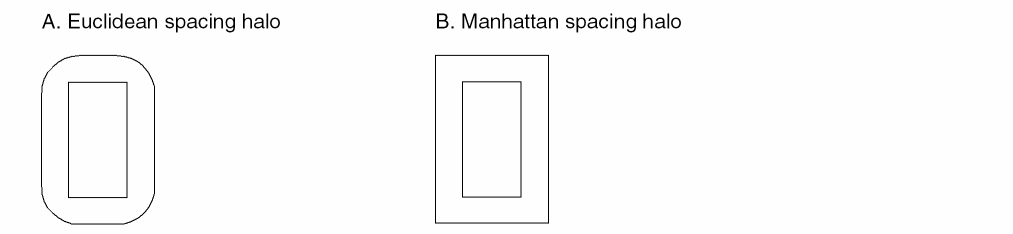
|
Virtuoso Studio design environment ASCII Technology File Definition:
Constraint name: minSpacing Value: manhattan
constraintGroups(
("foundry"
   spacings(
      ( minSpacing tx_layer g_spacing ['manhattan] )
   ) ;spacings
   orderedSpacings(
      ( minEnclosure tx_layer1 tx_layer2 g_enclosure ['manhattan] )
      ( minSpacing tx_layer1 tx_layer2 g_spacing ['manhattan] )
   ) ;orderedSpacings
   spacingTables(
       ("minSpacing" tx_layer1 [tx_layer2]
      (("width" nil nil ["length" nil nil] ))
       ( g_table )
      ['manhattan] )
   ) ;spacingTables
) ;foundry
);constraintGroups
|
|
DFII on CDB ASCII Technology File Definition:
NA
|
|
OpenAccess Constraint:
Parameter: oaConstraintParam: oaEuclidean
Value type: oaBoolean. If true, distance is measured in Euclidean directions. If false the direction is measured in Manhattan directions. Default is true.
Supported constraints: oacMinSpacing, oacMinClearance, oacMinExtension, oacMinTouchingDirectionExtension, and oacMinTouchingDirectionClearance
|
Minimum Spacing Constraint
This constraint specifies the minimum spacing between any two adjacent geometries on a specified layer. The spacing can be measured either in manhattan or euclidean metric (see Manhattan Corner Enclosure or Spacing Constraint). The value of the constraint can be based either on the width of the wider of the two shapes, on the width of the wider of the two shapes plus their parallel run length, on the width of both the shapes, or on the width of both the shapes plus their parallel run length. An optional parameter determines the spacing direction, horizontal or vertical, in which the constraint applies. Another optional parameter determines whether the constraint applies to power and ground nets.
|
Virtuoso Studio design environment ASCII Technology File Definition:
Constraint name: minSpacing
constraintGroups(
("foundry"
   spacings(
      ( minSpacing tx_layer ['horizontal | 'vertical | 'any]         ['sameNet ['PGNet] | 'sameMetal] g_space
        ['manhattan] )
      ...
   ) ;spacings
) ;foundry
)
constraintGroups(
("foundry"
   spacingTables(
      ( minSpacing tx_layer
         ( ("width" nil nil ["length"|"width" nil nil] ) ['horizontal |            'vertical | 'any] ['sameNet ['PGNet] | 'sameMetal]              [g_defaultValue] )
             (g_table)
             ['soft | 'hard] ['coincidentAllowed] ['manhattan] ['ref t_ref]
             ['description t_description]
      )
      ( minSpacing tx_layer
         ( ("twoWidths" nil nil "length" nil nil) ['horizontal |            'vertical | 'any] ['sameNet ['PGNet] | 'sameMetal]              [g_defaultValue] )
             (g_table) ['manhattan]
      )
      )
   ) ;spacingTables
) ;foundry
) ;constraintGroups
|
|
OpenAccess Constraint:
Class: oaLayerConstraint
Constraint type: oacMinSpacing
Value type: oaIntValue, oaInt1DTblValue(width), oaInt2DTblValue(width, length)
Parameter: oacWidthLengthTableTypeConstraintParamType, oaIntValue, oaWidthLengthTableType value oacTwoWidthParallelRunLengthTableType
Spacing table supports both >= and > semantic look up.
|
Minimum Center Spacing Constraint
|
Virtuoso Studio design environment ASCII Technology File Definition:
Constraint name: minCenterToCenterSpacing
constraintGroups(
("foundry"
   spacings(
      ("minCenterToCenterSpacing" tx_layer g_value)
      ...
   );spacings
);foundry
);constraintGroups
|
|
DFII on CDB ASCII Technology File Definition:
Rule name: minCenterToCenterSpacing
physicalRules(
   spacingRules(
      ("minCenterToCenterSpacing" tx_layer g_value)
   );spacingRules
);physicalRules
|
|
OpenAccess Constraint:
Class: oaLayerConstraint
Constraint type: oacMinCenterToCenterSpacing
Value type: oaIntValue
|
Minimum Diagonal Spacing Constraint
|
Virtuoso Studio design environment ASCII Technology File Definition:
Constraint name: minDiagonalSpacing
constraintGroups(
("foundry"
   spacings(
      ("minDiagonalSpacing" tx_layer g_value)
      ...
   );spacings
);foundry
);constraintGroups
constraintGroups(
("foundry"
   spacingTables(
      ("minDiagonalSpacing" tx_layer
         (
         ( ("width" nil nil ["length" nil nil] ) [ g_defaultValue ])
         (l_table)
         )
      )
   );spacingTables
);foundry
);constraintGroups
|
|
DFII on CDB ASCII Technology File Definition:
Rule name: minDiagonalSpacing
physicalRules(
   spacingRules(
      ("minDiagonalSpacing" tx_layer g_value)
   );spacingRules
);physicalRules
|
|
OpenAccess Constraint: object
Class: oaLayerConstraint
Constraint type: oacMinDiagonalSpacing
Value type: oaIntValue, oaInt1DTblValue(width), oaInt2DTblValue(width, length)
|
Minimum Diagonal Width Constraint
|
Virtuoso Studio design environment ASCII Technology File Definition:
Constraint name: minDiagonalWidth
constraintGroups(
("foundry"
   spacings(
      ("minDiagonalWidth" tx_layer g_width)
      ...
   );spacings
);foundry
);constraintGroups
|
|
DFII on CDB ASCII Technology File Definition:
Rule name: minDiagonalWidth
physicalRules(
   spacingRules(
      ("minDiagonalWidth" tx_layer g_wdith)
   );spacingRules
);physicalRules
|
|
OpenAccess Constraint:
Class: oaLayerConstraint
Constraint type: oacMinDiagonalWidth
Value type: oaIntValue,
|
Minimum Different Potential Spacing Constraint
|
Virtuoso Studio design environment ASCII Technology File Definition:
Constraint name: minDiffNetSpacing
constraintGroups(
("foundry"
   spacings(
      ("minDiffNetSpacing" tx_layer g_value)
      ...
   );spacings
);foundry
);constraintGroups
|
|
DFII on CDB ASCII Technology File Definition:
Rule name: minDiffNetSpacing
physicalRules(
   spacingRules(
      ("minDiffNetSpacing" tx_layer g_value)
   );spacingRules
);physicalRules
|
|
OpenAccess Constraint:
Class: oaLayerConstraint
Constraint type: oacMinDiffPotentialSpacing
Value type: oaIntValue,
|
Minimum Space between Fill Pattern and Real Design Object Constraint
|
Virtuoso Studio design environment ASCII Technology File Definition:
Constraint name: minFillToShapeSpacing
constraintGroups(
("foundry"
   spacings(
      ("minFillToShapeSpacing" tx_layer g_value)
      ...
   );spacings
);foundry
);constraintGroups
|
|
DFII on CDB ASCII Technology File Definition:
Rule name: minFillToShapeSpacing and fillActiveSpacing
physicalRules(
   spacingRules(
      ("minFillToShapeSpacing" tx_layer g_value)
   );spacingRules
The LEF metal filling value, FILLACTIVESPACING mapped to the fillActiveSpacing rule in the spacingRules subsection.
physicalRules(
   spacingRules(
      ("fillActiveSpacing" tx_layer g_value)
   );spacingRules
);physicalRules
|
|
OpenAccess Constraint:
Class: oaLayerConstraint
Constraint type: oacMinFillPatternSpacing
Value type: oaIntValue
|
Minimum Proximity (Influence) Spacing Constraint
|
Virtuoso Studio design environment ASCII Technology File Definition:
Constraint name: minInfluenceSpacing
constraintGroups(
("foundry"
   spacings(
      ("minInfluenceSpacing" tx_layer g_value)
      ...
   );spacings
);foundry
);constraintGroups
constraintGroups(
("foundry"
   spacingTables(
      ("minInfluenceSpacing" tx_layer
         (
         ("width" nil nil ["distance" nil nil] ) [ g_defaultValue ] )
         (l_table)
         )
      )
   )
);foundry
);constraintGroups
|
|
DFII on CDB ASCII Technology File Definition:
Rule name: minInfluenceSpacing
physicalRules(
   tableSpacingRules(
      ("minInfluenceSpacing" tx_layer )
      ("width" nil nil ["distance" nil nil])
      (l_table)
   );tableSpacingRules
);physicalRules
The LEF statement SPACINGTABLE PARALLELRUNLENGTH previously mapped to minSpacing in the tableSpacingRules subsection.
The LEF statement SPACINGTABLE INFLUENCE previously mapped to "minSpacingInfluence" under the tableSpacingRules subsection.
|
|
OpenAccess Constraint:
Class: oaLayerConstraint
Constraint type: oacMinProximitySpacing with 2 parameters, width and distance.
Value type: oaIntValue, oaInt1DTblValue(width), oaInt2DTblValue(width, distance)
Spacing table supports both >= and > look up.
|
Minimum Proximity (Influence) Spacing Constraint for Protruding Wires or Stubs
|
Virtuoso Studio design environment ASCII Technology File Definition:
Constraint name: minStubInfluenceSpacing
constraintGroups(
("foundry"
   spacings(
      ("minStubInfluenceSpacing" tx_layer g_spacing
      ...
   );spacings
);foundry
);constraintGroups
constraintGroups(
("foundry"
   spacingTables(
      ("minStubInfluenceSpacing" tx_layer
         (
         ( ("width" nil nil ["distance" nil nil] ) )
         (g_table)
         )
      )
   ) ; spacingTables
);foundry
);constraintGroups
LEF spacing semantic has “>=”. The spacing table influence is not mapped to this constraint. The influence halo of the larger shape is given by the minSpacing constraint.
|
|
DFII on CDB ASCII Technology File Definition:
Rule name: minStubInfluenceSpacing
physicalRules(
   spacingRules(
      ("minStubInfluenceSpacing" tx_layer g_value)
   );spacingRules
);physicalRules
physicalRules(
   spacingRules(
      ( minSpacingRange   tx_layer ("minSpacingValue RANGE minWidth maxWidth INFLUENCE infvalue")
   ) ;spacingRules
) ;physicalRules
minSpacingRange with the INFLUENCE keyword maps to a 2D table minStubInfluenceSpacing constraint.
"RANGE stubMinWidth stubMaxWidth" are ignored with warning message.
minWidth is used as rows and influenceValue is used as columns. The values are minSpacingValues
|
|
OpenAccess Constraint:
Class: oaLayerConstraint
Constraint type: oacMinProtrudedProximitySpacing
Value type: oaIntValue, oaInt1DTblValue(width), oaInt2DTblValue(width, distance)
Spacing table supports both >= and > look up.
|
Minimum Spacing Constraint (sameNet)
|
Virtuoso Studio design environment ASCII Technology File Definition:
Constraint name: minSameNetSpacing
constraintGroups(
("foundry"
   spacings(
      ("minSameNetSpacing" tx_layer g_value)
      ...
   spacingTables(
      ( "minSameNetSpacing" tx_layer
      (( "width" nil nil ))
      ( g_table )
      )
   ) ;spacingTables
   );spacings
);foundry
);constraintGroups
|
|
DFII on CDB ASCII Technology File Definition:
Rule names: minSameNetSpacing, minNotch and sameNet
physicalRules(
   spacingRules(
      ("minSameNetSpacing" tx_layer g_value)
   )
)
physicalRules(
   spacingRules(
      ("minNotch" tx_layer g_value)
   );spacingRules
);physicalRules
The LEF SPACING statement previously mapped same net spacing rules and stacked vias. Without the STACK statement, same net spacing and was mapped to the sameNet rule in the spacingRules subsection.
physicalRules(
   spacingRules(
      ("sameNet" tx_layer g_value)
   );spacingRules
);physicalRules
|
|
OpenAccess Constraint:
Class: oaLayerConstraint
Constraint type: oacMinSameNetSpacing
Value type: oaIntValue
|
Minimum Adjacent Via Spacing Constraint
This constraint specifies the required minimum distance between adjacent via cuts and depends on the number of adjacent cut shapes within the specified distance. A via cut is adjacent if it is within the specified distance from another cut in any direction including a 45-degree angle. Optional parameters can be used to determine the following:
-
Whether the cut spacing is to be measured edge-to-edge or center-to-center
-
Whether the constraint applies to shapes having any connectivity, to shapes having only same-net connectivity, or only to cut shapes on the same metal
-
Whether the constraint applies to vias on power and ground nets
The constraint can optionally apply only if the cut shapes are either on the same net or are overlapped by the same metal shape or are overlapped by the same metal shape above and below which cover the overlap area between the cuts. The number of neighboring cuts can also be specified.
This constraint supports 32 nm design rules. The cutClass constraint must be defined before this constraint. For more information, see viaSpacing in Virtuoso Technology Data ASCII Files Reference.
|
Virtuoso Studio design environment ASCII Technology File Definition:
Constraint name: viaSpacing
constraintGroups(
("foundry"
   spacings(
      ( viaSpacing tx_cutLayer ['centerToCenter]
      ['sameNet|'sameMetal|'sameMetalOverlap|'sameVia]
      ['exceptSamePGNet]
      ['cutClass g_width | (g_width g_length) | t_name]
      ['exactAligned g_numAlignedCuts ['exactSpacing]]
      'numCuts g_numCuts 'distance g_distance g_spacing )
   ) ;spacings
) ;foundry
) ;constraintGroups
See Mapping of the viaSpacing Table Definition.
|
|
DFII on CDB ASCII Technology File Definition:
Rule name: viaSpacing
physicalRules(
   tableSpacingRules(
   ( "viaSpacing"  "via1"
      ( "adjacentVias"   ( g_numCut{3|4})    nil )
      (
      (g_numAdjacentVia   ">="   )   g_viaCutSpacing
   );tableSpacingRules
);physicalRules
|
|
OpenAccess Constraint:
Class: oaLayerConstraint
Constraint type: oacMinAdjacentViaSpacing
Value type: oaIntValue: spacing
Parameters: oacDistanceConstraintParamType,
oacNumCutsConstraintParamType,
oaBoolean oacCenterToCenterConstraintParamType,
oaIntValue oacConnectivityTypeConstraintParamType,
oaBoolean oacExceptSamePGNetConstraintParamType
|
|
LEF Syntax:
SPACING cutSpacing [CENTERTOCENTER] [SAMENET|SAMEMETAL|SAMEVIA]
ADJACENTCUTS {2|3|4} [EXACTALIGNED exactAlignedCut] WITHIN cutWithin
[EXCEPTSAMEPGNET] [CUTCLASS className]
|
Mapping of the viaSpacing Table Definition
In CDB, the viaSpacing rule can be defined using a table value. In OpenAccess the viaSpacing constraint is defined using a scalar value not a table value.
When mapping this rule to the Virtuoso environment, a table is converted to multiple scalar
viaSpacing constraints which will contain one value (spacing) and two parameters (number of adjacent cuts and distance).
CDB
( "viaSpacing"    "Cont"
   ("adjacentVias" nil nil)
   (
     3    0.4 4 0.5
   )
)
Virtuoso Studio design environment
( viaSpacing "Cont" (3 0.4 0.4) )
( viaSpacing "Cont" (4 0.4 0.5) )
Minimum Via Spacing Constraint
This constraint specifies the via cut spacing for cuts on the same net or for cuts on the same metal. Optional parameters can be used to determine the following:
-
Whether the cut spacing is to be measured edge-to-edge or center-to-center
-
Whether the constraint applies to shapes having any connectivity, to shapes having only same-net connectivity, or only to cut shapes on the same metal
-
Whether the cuts must have an area larger than a specified value before the spacing applies
|
Virtuoso Studio design environment ASCII Technology File Definition:
Constraint name: minViaSpacing
constraintGroups(
("foundry"
   spacings(
      ( minViaSpacing tx_cutLayer ['centerToCenter] ['sameNet|'sameMetal]
        ['area g_area] g_spacing )
   ) ;spacings
) ;foundry
) ;constraintGroups
constraintGroups(
("foundry"s
   spacingTables(
      ( minViaSpacing tx_cutLayer
      ( ("width" nil nil ["width" nil nil]) ['centerToCenter]           ['sameNet|'sameMetal] ['area g_area] [g_default] )
       (g_table)
       )
   ) ;spacingTables
) ;foundry
) ;constraintGroups
|
|
OpenAccess Constraint:
Class: oaLayerConstraint
Constraint type: oacMinViaSpacing
Value type: oaIntValue,
oaInt1DTblValue (width),
oaInt2DTblValue (width, width): the spacing
Parameters: oaBoolean oacCenterToCenterConstraintParamType,
oaIntValue oacConnectivityTypeConstraintParamType,
oaIntValue oacAreaConstraintParamType
|
|
LEF Syntax:
SPACING cutSpacing [CENTERTOCENTER] [SAMENET | SAMEMETAL] AREA cutArea
|
Merge Allowed Spacing Constraint
|
Virtuoso Studio design environment ASCII Technology File Definition:
Constraint name: maxFilling
constraintGroups(
("foundry"
   spacings(
      ("maxFilling" tx_layer g_value)
      ...
   );spacings
);foundry
);constraintGroups
|
|
DFII on CDB ASCII Technology File Definition:
Rule name: maxFilling
physicalRules(
   spacingRules(
      (maxFilling tx_layer g_value)
   );spacingRules
);physicalRules
|
|
OpenAccess Constraint:
Class: oaLayerConstraint
Constraint type: oacMergeSpaceAllowed
Value type: oaIntValue
|
Minimum Width Constraint
|
Virtuoso Studio design environment ASCII Technology File Definition:
Constraint name: minWidth
constraintGroups(
("foundry"
   spacings(
      ("minWidth" tx_layer g_width)
      ...
   );spacings
);foundry
);constraintGroups
|
|
DFII on CDB ASCII Technology File Definition:
Rule name: minWidth
physicalRules(
   spacingRules(
      ("minWidth" tx_layer g_width)
   );spacingRules
);physicalRules
The rule defaultMinWidth is mapped according to the following convention:
-
If the technology file contains
defaultMinWidth but not minWidth, defaultMinWidth maps to the minWidth constraint with this value to both the foundry and the LEFDefaultRouteSpec constraint groups. -
If both rules are present and
minWidth < defaultMinWidth, then the defaultMinWidth rule is mapped to a minWidth constraint in the LEFDefaultRouteSpec constraint group and the minWidth constraint is moved to the foundry constraint group. -
If both rules are present and
minWidth > defaultMinWidth, the minWidth constraint moves to the LEFDefaultRouteSpec group and the defaultMinWidth constraint maps to a minWidth constraint in the foundry constraint group.
The rule defaultWidth is mapped to the minWidth constraint in the LEFDefaultRouteSpec constraint group.
|
|
OpenAccess Constraint:
Class: oaLayerConstraint
Constraint type: oacMinWidth
Value type: oaIntValue
|
Minimum Protrusion Width Constraint
|
Virtuoso Studio design environment ASCII Technology File Definition:
Constraint name: protrusionWidth
constraintGroups(
("foundry"
   spacings(
      ("protrusionWidth" tx_layer ( g_length g_width g_protrusionWidth )
      )
...
   );spacings
);foundry
);constraintGroups
where:
g_protrusionWidth is the minimum width, in user units, of the protrusion.
g_length is the length, in user units, that the protrusion length must be less than for the constraint to apply.
g_width is the minimum width of the wire to which the protrusion connects for the constraint to apply.
|
|
DFII on CDB ASCII Technology File Definition:
Rule name: protrusionWidth
physicalRules(
   spacingRules(
      ("protrusionWidth" tx_layer (g_length g_width g_value1) )
   );spacingRules
);physicalRules
|
|
OpenAccess Constraint:
Class: oaLayerConstraint
Constraint type: oacMinProtrusionWidth with 2 width parameters.
Value type: oaIntValue
|
Maximum Width Constraint
|
Virtuoso Studio design environment ASCII Technology File Definition:
Constraint name: maxWidth
constraintGroups(
("foundry"
   spacings(
      ("maxWidth" tx_layer g_width)
      ...
   );spacings
);foundry
);constraintGroups
|
|
DFII on CDB ASCII Technology File Definition:
Rule name: maxWidth
physicalRules(
   spacingRules(
      ("maxWidth" tx_layer g_width)
   );spacingRules
);physicalRules
|
|
OpenAccess Constraint:
Class: oaLayerConstraint
Constraint type: oacMaxWidth
Value type: oaIntValue
|
Minimum Length Constraint
|
Virtuoso Studio design environment ASCII Technology File Definition:
Constraint name: minLength
constraintGroups(
("foundry"
   spacings(
      ("minLength" tx_layer g_length)
      ...
   );spacings
);foundry
);constraintGroups
|
|
DFII on CDB ASCII Technology File Definition:
Rule name: minLength
physicalRules(
   spacingRules(
      ("minLength" tx_layer g_length)
   );spacingRules
);physicalRules
|
|
OpenAccess Constraint:
Class: oaLayerConstraint
Constraint type: oacMinLength
Value type: oaIntValue
|
Maximum Length Constraint
|
Virtuoso Studio design environment ASCII Technology File Definition:
Constraint name: maxLength
constraintGroups(
("foundry"
   spacings(
      ("maxLength" tx_layer g_length)
      ...
   );spacings
);foundry
);constraintGroups
|
|
DFII on CDB ASCII Technology File Definition:
Rule name: maxLength
physicalRules(
   spacingRules(
      ("maxLength" tx_layer g_length)
   );spacingRules
);physicalRules
|
|
OpenAccess Constraint:
Class: oaLayerConstraint
Constraint type: oacMaxLength
Value type: oaIntValue
|
Minimum Number of Cuts Constraint
This constraint specifies the minimum number of cuts a via can have when it connects either two wide wire shapes or a wide shape to a pin. The constraint applies when the width of the wire or pin shape being connected is more than the width specified by this constraint. An optional parameter can be used to specify the distance at which cut shapes can be from each other.
|
Virtuoso Studio design environment ASCII Technology File Definition:
Constraint name: minNumCut
constraintGroups(
("foundry"
   spacingTables(
      ( minNumCut tx_cutLayer
         (( "width" nil nil ) ['distanceWithin g_within] [ g_defaultValue ])
         ( g_table )
      )
   ) ;spacingTables
) ;foundry
) ;constraintGroups
When a LEF file is read in, if this constraint is set for any routing layers then the information is moved to the cut layers above and below the routing layer.
In case of conflicts, warnings are issued. LEF In will only store the value on the cut layers. LEF Out reconstructs the ABOVE/BELOW LEF data by looking at the values stored on the CUT layers.
|
|
DFII on CDB ASCII Technology File Definition:
Rule name: minNumCut
physicalRules(
   spacingRules(
      ("minNumCut" (g_numberOfCuts "width" g_width) )
   );spacingRules
);physicalRules
|
|
OpenAccess Constraint:
Class: oaLayerConstraint (cut layer only)
Constraint type: oacMinNumCut
Value type: oaInt1DTblValue (width), number of cuts
Parameters: oacDistanceWithinConstraintParamType
|
|
LEF Syntax:
[MINIMUMCUT numCuts WIDTH width [WITHIN cutDistance]
[FROMABOVE|FROMBELOW]
[LENGTH wireLength WITHIN wireDistance];]...
|
Minimum Number of Cuts on Protrusion Constraint
This constraint specifies the number of via cuts required to connect a thin wire to a wide wire or pin. The constraint applies when the wide wire width and length exceed those specified. An optional parameter specifies the distance at which cut shapes can be from each other.
|
Virtuoso Studio design environment ASCII Technology File Definition:
Constraint name: minProtrusionNumCut
constraintGroups(
( "foundry"
      memberConstraintGroups(
        "protrusionGroup"
      ) ;memberConstraintGroups
   ) ;spacings
) ;foundry
( "protrusionGroup" nil nil 'and
      spacings(
      ( minProtrusionNumCut tx_cutLayer 'distance g_distance 'length g_length        'width g_width ['distanceWithin g_distanceWithin] g_numCuts )
      ( minProtrusionNumCut tx_cutLayer 'distance g_distance 'length g_length        'width g_width ['distanceWithin g_distanceWithin] g_numCuts )
     ) ;spacings
) ;protrusionGroup
) ;constraintGroups
|
|
OpenAccess Constraint:
Class: oaLayerConstraint (cut layer only)
Constraint type: oacMinProtrusionNumCut with 3 possible parameters, distance, length and width
Value type: oaIntValue, number of cuts (width, length, distance)
Parameters: oacDistanceWithinConstraintParamType cutDistance, oacWidthConstraintParamType,
oacLengthConstraintParamType, oacDistanceConstraintParamType
|
|
LEF Syntax:
[MINIMUMCUT numCuts WIDTH width [WITHIN cutDistance]
[FROMABOVE|FROMBELOW]
[LENGTH wireLength WITHIN wireDistance];]...
|
Allowed Shape Angles Constraint
This constraint specifies the allowed default geometry orientations (all angles, 45/135 degree and orthogonal, orthogonal only). The default orientation applies to all the layers in the technology.
|
Virtuoso Studio design environment ASCII Technology File Definition:
Constraint name: allowedShapeAngles
constraintGroups(
("foundry"
   allowedShapeAngles( ["anyAngle"|"orthogonal"|"diagonal"]
         ( tx_layer "anyAngle" )
         ( tx_layer "orthogonal" )
         ( tx_layer "diagonal" )
   ) ;allowedShapeAngles
) ;foundry
) ;constraintGroups
|
|
OpenAccess Constraint:
Class: oaSimpleConstraint, oaLayerConstraint
Constraint type: oacShapeAngle, oacLayerShapeAngle
Value type: oaShapeAngleType,
oaIntValue: all, orthogonal, diagonal
|
Diagonal Shapes Allowed Constraint
|
Virtuoso Studio design environment ASCII Technology File Definition:
Constraint name: diagonalShapesAllowed
constraintGroups(
("foundry"
   spacings(
      ("diagonalShapesAllowed" tx_layer g_value)
      ...
   ) ;spacings
) ;foundry
) ;constraintGroups
|
|
DFII on CDB ASCII Technology File Definition:
Constraint name: diagonalShapesAllowed
physicalRules(
   spacingRules(
      ("diagonalShapesAllowed" tx_layer g_value)
   ) ;spacingRules
);physicalRules
|
|
OpenAccess Constraint:
Class: oaLayerConstraint
Constraint type: oacDiagonalShapesAllowed
Value type: oaBoolValue
|
Maximum Tap Spacing Constraint
|
Virtuoso Studio design environment ASCII Technology File Definition:
Constraint name: maxTapSpacing
constraintGroups(
("foundry"
   spacings(
      ("maxTapSpacing" tx_layer g_spacing)
      ...
   ) ;spacings
) ;foundry
) ;constraintGroups
|
|
DFII on CDB ASCII Technology File Definition:
physicalRules(
   spacingRules(
      ("maxTapSpacing" tx_layer g_spacing)
   ) ;spacingRules
) ;physicalRules
|
|
OpenAccess Constraint:
Class: oaLayerConstraint
Constraint type: oacMaxTapSpacing
Value type: oaIntValue
|
Minimum Notch Spacing
When the length of a notch is less than the specified distance, the spacing within the notch should satisfy the minimum notch spacing.
|
Virtuoso Studio design environment ASCII Technology File Definition:
Constraint name: minNotchSpacing
constraintGroups(
("foundry"
   spacings(
      ( minNotchSpacing tx_layer 'notchLength g_notchLength g_spacing )
   ) ;spacings
) ;foundry
) ;constraintGroups
|
|
DFII on CDB ASCII Technology File Definition:
NA
|
|
OpenAccess Constraint:
Class: oaLayerConstraint
Constraint type: oacMinNotchSpacing
Value type: oaIntValue, minimum notch spacing
Parameters: oacNotchLength
|
|
LEF Syntax:
[SPACING minNotchSpacing NOTCHLENGTH minNotchLength ;]
|
Minimum End of Notch Spacing
The end of a notch is the bottom end of a U-shaped notch. This constraint specifies the minimum spacing between the notch and the shapes (on the same layer) overlapping within the extent of the notch. This constraint applies if all of the following hold true:
-
The width of the end of notch is less than the specified width
-
The notch length is greater than or equal to the minimum notch length
-
The notch spacing is less than or equal to the minimum notch spacing
|
Virtuoso Studio design environment ASCII Technology File Definition:
Constraint name: minEndOfNotchSpacing
constraintGroups(
("foundry"
   spacings(
      ( minEndOfNotchSpacing tx_layer 'notchWidth g_notchWidth
        'notchLength g_notchLength 'notchSpacing g_notchSpacing
         g_endOfNotchSpacing )
   ) ;spacings
) ;foundry
) ;constraintGroups
|
|
DFII on CDB ASCII Technology File Definition:
NA
|
|
OpenAccess Constraint:
Class: oaLayerConstraint
Constraint type: oacMinEndOfNotchSpacing
Value type: oaIntValue, minimum end of notch spacing
Parameters: oacNotchWidthConstraintParamType,
oacNotchLengthConstraintParamType,
oacNotchSpacingConstraintParamType
|
|
LEF Syntax:
[[SPACING minNotchSpacing [ENDOFNOTCHWIDTH endOfNotchWidth NOTCHSPACING minNotchSpacing NOTCHLENGTH minNotchLength] ;]
|
Minimum Wire Extension Constraint
|
Virtuoso Studio design environment ASCII Technology File Definition:
Constraint name: minWireExtension
constraintGroups(
("LEFDefaultRouteSpec"
   spacings(
      ("minWireExtension" tx_layer g_spacing [g_distance])
   ) ;spacings
) ;LEFDefaultRouteSpec
) ;constraintGroups
|
|
DFII on CDB ASCII Technology File Definition:
N/A
|
|
OpenAccess Constraint:
Class: oaLayerConstraint
Constraint type: oacMinWireExtension
Value type: oaIntValue
|
Minimum Boundary Extension Constraint
|
Virtuoso Studio design environment ASCII Technology File Definition:
Constraint name: minPRBoundaryExtension
constraintGroups(
("foundry"
   spacings(
      ("minPRBoundaryExtension" tx_layer g_extension)
      ...
   ) ;spacings
) ;foundry
) ;constraintGroups
|
|
DFII on CDB ASCII Technology File Definition:
Rule name: minPRBoundaryExtension and minExtension (with the LPP prBoundary).
physicalRules(
   spacingRules(
      ("minPRBoundaryExtension" tx_layer g_extension)
   ) ;spacingRules
) ;physicalRules
physicalRules(
   spacingRules(
      ("minExtension" "prBoundary" [tx_layerPurpose] g_extension)
   ) ;spacingRules
) ;physicalRules
Note: The two layer rule minExtension on LPP prBoundary boundary is mapped to the single layer constraint minPRBoundaryExtension. For example:
( minExtension("prBoundary" "boundary") "nwell" 0.4 )
maps to:
( "minPRBoundaryExtension" "nwell" 0.4 )
For more information, see Mapping Shape Based Boundaries.
For information about mapping the two layer minExtension rule, see Minimum Overlap Constraint.
|
|
OpenAccess Constraint:
Class: oaLayerConstraint
Constraint type: oacMinimumBoundaryExtension
Value type: oaIntValue
|
Keep prBoundary Shared Edges Constraint
|
Virtuoso Studio design environment ASCII Technology File Definition:
Constraint name: keepPRBoundarySharedEdges
constraintGroups(
("foundry"
   spacings(
      ( keepPRBoundarySharedEdges tx_layer )
   );spacings
);foundry
);constraintGroups
|
|
DFII on CDB ASCII Technology File Definition:
NA
|
|
OpenAccess Constraint:
Class: oaLayerConstraint
Constraint type: oacKeepAlignedShapeAndBoundary
Value type: oaBooleanValue
Objects: oaPRBoundary.
|
Minimum Boundary Interior Halo Constraint
|
Virtuoso Studio design environment ASCII Technology File Definition:
Constraint name: minPRBoundaryInteriorHalo
constraintGroups(
("foundry"
   spacings(
      ("minPRBoundaryInteriorHalo" tx_layer g_distance ['coincidentAllowed])
      ...
   ) ;spacings
) ;foundry
) ;constraintGroups
|
|
DFII on CDB ASCII Technology File Definition:
Rule name: minPRBoundaryInteriorHalo
physicalRules(
   spacingRules(
      ("minPRBoundaryInteriorHalo" tx_layer g_extension)
   ) ;spacingRules
) ;physicalRules
physicalRules(
   spacingRules(
      ("minEnclosure" "prBoundary" [tx_layerPurpose] g_extension)
   ) ;spacingRules
) ;physicalRules
Note: The two layer rule minEnclosure on LPP prBoundary boundary is mapped to the single layer constraint minPRBoundaryInteriorHalo. For example:
( minEnclosure("prBoundary" "boundary") "metal1" 0.3)
maps to:
( "minPRBoundaryInteriorHalo" "metal1" 0.3 )
For more information, see Mapping Shape Based Boundaries.
For information about mapping the two layer minEnclosure rule, see Minimum Extension Constraint.
|
|
OpenAccess Constraint:
Class: oaLayerConstraint
Constraint type: oacMinBoundaryInteriorHalo
Value type: oaIntValue
|
Maximum Diagonal Edge Length Constraint
|
Virtuoso Studio design environment ASCII Technology File Definition:
Constraint name: maxDiagonalEdgeLength
constraintGroups(
("foundry"
   spacings(
      ( maxDiagonalEdgeLength tx_layer g_length )
   ) ;spacings
);foundry
);constraintGroups
|
|
DFII on CDB ASCII Technology File Definition:
NA
|
|
OpenAccess Constraint:
Class: oaLayerConstraint
Constraint type: oacMaxDiagonalEdgeLength
Value type: oaIntValue
|
Redundant Via Setback Constraint
A redundant via is inserted in order to increase the successful connection rate of the metal shapes when there is the possibility of via failure. When placing the via down on the larger metal shape, vias conform to the minimum enclosure rule. In case of redundant vias, larger enclosure values are required for such vias when both the vias are on the same edge.
|
Virtuoso Studio design environment ASCII Technology File Definition:
Constraint name: redundantViaSetback
constraintGroups(
("foundry"
   spacingTables(
      ( "redundantViaSetback" tx_layer1 tx_layer2
      (( "width" nil nil ))
      ( g_table )
      )
   ) ;spacingTables
) ;foundry
);constraintGroups
|
|
DFII on CDB ASCII Technology File Definition:
NA
|
|
OpenAccess Constraint:
Class: oaLayerPairConstraint (not symmetric)
Constraint type: oacMinRedundantViaSetback
Value type: oaInt1DTblValue(width)
|
Maximum Routing Distance Constraint
Maximum allowed routing distance is used to restrict how much routing can be done on a particular layer and is applied on a per net basis. Usually used for poly routing.
|
Virtuoso Studio design environment ASCII Technology File Definition:
Constraint name: maximumRoutingDistance
constraintGroups(
("LEFDefaultRouteSpec"
   interconnect(
      ( maximumRoutingDistance tx_layer g_distance
   ) ;interconnect
) ;LEFDefaultRouteSpec
) ;constraintGroups
|
|
DFII on CDB ASCII Technology File Definition:
NA
|
|
OpenAccess Constraint:
Class: oaLayerConstraint
Constraint type: oacMaxRoutingDistance
Value type: oaIntValue
Objects: oacScalarNetType, oacBusNetBitType
|
Minimum Parallel Via Spacing Constraint
This constraint supports 32 nm design rules. The cutClass constraint must be defined before this constraint. For more information, see minParallelViaSpacing in Virtuoso Technology Data ASCII Files Reference.
This constraint is similar to Minimum Parallel Via Clearance Constraint.
|
Virtuoso Studio design environment ASCII Technology File Definition:
Constraint name: minParallelViaSpacing
constraintGroups(
("foundry"
   spacings(
       ( minParallelViaSpacing tx_cutLayer
        ['centerToCenter] ['exceptSameNet|'exceptSameMetal|'exceptSameVia]
        g_spacing)
   ) ;spacings
) ;foundry
);constraintGroups
|
|
DFII on CDB ASCII Technology File Definition:
NA
|
|
OpenAccess Constraint:
Class: oaLayerConstraint
Constraint type: oacMinParallelViaSpacing
Value type: oaIntValue: spacing
Parameters:
-
oaIntValue enum
cdcExceptConnectivityTypeConstraintParamType: except same net, except same metal, except same via:
   cdcSameNetConnectivityType
   cdcContiguousShapesConnectivityType (default)
cdcSameViaConnectivityType -
oaBooleanValue
oacCenterToCenterConstraintParamType: 'centerToCenter
|
|
LEF Syntax:
SPACING cutSpacing [CENTERTOCENTER] PARALLELOVERLAP
[EXCEPTSAMENET|EXCEPTSAMEMETAL|EXCEPTSAMEVIA]
|
Minimum Parallel Within Via Spacing Constraint
For more information, see minParallelWithinViaSpacing in Virtuoso Technology Data ASCII Files Reference.
|
Virtuoso Studio design environment ASCII Technology File Definition:
Constraint name: minParallelWithinViaSpacing
constraintGroups(
("foundry"
   spacings(
       ( minParallelWithinViaSpacing tx_cutLayer
        ['centerToCenter] ['exceptSameNet]
        'cutDistance g_distance g_spacing)
   ) ;spacings
) ;foundry
);constraintGroups
|
|
DFII on CDB ASCII Technology File Definition:
NA
|
|
OpenAccess Constraint:
Constraint type: oaLayerConstraint
Constraint name: cdcMinParallelWithinViaSpacing
Value type: oaIntValue: spacing
Parameters:
-
oaIntValue
oacCutDistanceConstraintParamType: parallel within -
oaIntValue enum
cdcExceptConnectivityTypeConstraintParamType: except same net, except same metal, except same via. Only same net applies: cdcSameNetConnectivityType -
oaBooleanValue
oacCenterToCenterConstraintParamType
|
|
LEF Syntax:
SPACING cutSpacing [CENTERTOCENTER] PARALLELWITHIN within [EXCEPTSAMENET];
|
Minimum Parallel Span Spacing Constraint
For more information, see minParallelSpanSpacing in Virtuoso Technology Data ASCII Files Reference.
|
Virtuoso Studio design environment ASCII Technology File Definition:
Constraint name: minParallelSpanSpacing
constraintGroups(
("foundry"
   spacingTables(
       ( minParallelSpanSpacing tx_layer1
       ( ( "span" nil nil "span" nil nil ) 'length g_length [g_defaultValue] )
       (g_table)
       )
   ) ;spacingTables
) ;foundry
);constraintGroups
|
|
OpenAccess Constraint:
Constraint type: oaLayerConstraint
Constraint name: cdcMinParallelSpanSpacing
Value: oaInt2DTblValue: (span length, span length) minimum spacing
Parameters:
-
oaIntValue
oacLengthConstraintParamType: parallel run length
|
|
LEF Syntax:
SPACINGTABLE PARALLELSPANLENGTH PRL runLength
{SPANLENGTH spanLength {spacing}...};
|
Minimum Same Metal Shared Edge Via Spacing Constraint
For more information, see minSameMetalSharedEdgeViaSpacing in Virtuoso Technology Data ASCII Files Reference. The cutClass constraint must be defined before this constraint.
|
Virtuoso Studio design environment ASCII Technology File Definition:
Constraint name: minSameMetalSharedEdgeViaSpacing
constraintGroups(
("foundry"
spacings(
( minSameMetalSharedEdgeViaSpacing tx_cutLayer
'within g_within ['above]
['cutClass g_width|(g_width g_length)|t_name]
['exceptTwoEdges] ['numCuts g_cuts] g_spacing)
) ;spacings
) ;foundry
);constraintGroups
where the cut class width and length will be mapped to the previously defined cut class constraint whose name parameter matches the cut class width and length if defined, or will match the cut class width and length directly.
|
|
OpenAccess Constraint:
Constraint type: oaLayerConstraint
Constraint name: cdcMinSameMetalSharedEdgeViaSpacing
Value: oaIntValue: spacing
Parameters:
-
oaDualIntValue
cdcCutClassConstraintParamType: cut class (width, length) -
oaIntValue
oacParallelEdgeWithinConstraintParamType: parallel within
cdcExceptSameViaCountConstraintParamType: except same via num cuts -
oaBooleanValue
cdcExceptTwoEdgesConstraintParamType
cdcAboveOnlyConstraintParamType
|
|
LEF Syntax:
SPACING cutSpacing SAMEMETALSHAREDEDGE parWithin [ABOVE] [CUTCLASS class]
[EXCEPTTWOEDGES] [EXCEPTSAMEVIA numCut];
|
Minimum End of Line Spacing Constraint
This constraint supports 32 nm design rules. For more information, see minEndOfLineSpacing in Virtuoso Technology Data ASCII Files Reference.
|
Virtuoso Studio design environment ASCII Technology File Definition:
Constraint name: minEndOfLineSpacing
constraintGroups(
("foundry"
spacings(
( minEndOfLineSpacing tx_layer 'width g_width ['oppWidth g_oppWidth]
'distance g_distance
['endToEndSpace g_endToEndSpace ['otherEndWidth g_otherEndWidth]]
['maxLength g_maxLength | 'minLength g_minLength ['twoSides]]
['equalRectWidth]
['paraEdgeWithin g_parWithin 'paraEdgeSpace 'g_parSpace
['paraEdgeCount g_edgeCount] ['subtractWidth g_subtractWidth]
['paraMinLength g_parMinLength]]
['encloseDistance g_encloseDist 'cutToMetalSpace
g_cutToMetalSpace ['above|'below] ['allCuts]] g_spacing
) ;spacings
) ;foundry
);constraintGroups
|
|
DFII on CDB ASCII Technology File Definition:
NA
|
|
OpenAccess Constraint:
Class: oaLayerConstraint
Constraint type: oacMinEndOfLineSpacing
Value type: oaIntValue
Parameters:
-
oaIntValue:
oacWidthConstraintParamType: 'width (end of line width)
oacDistanceConstraintParamType: 'distance (within)
oacParallelEdgeSpaceConstraintParamType: 'paraEdgeSpace (parallel edge spacing)
oacParallelEdgeWithinConstraintParamType: 'paraEdgeWithin (parallel edge within)
oacCountConstraintParamType: 'paraEdgeCount (number of parallel edges)
cdcMinOppositeWidthConstraintParamType: 'oppWidth (opposite width)
cdcEndToEndSpacingConstraintParamType: 'endToEndSpace (end to end spacing)
cdcOtherEndWidthConstraintParamType: 'otherEndWidth (other end width)
oacMaxLengthConstraintParamType: 'maxLength (maximum length)
cdcMinLengthConstraintParamType: 'minLength (minimum length)
cdcParallelEdgeMinLengthConstraintParamType: 'paraMinLength (minimum length of end of line for parallel edge check)
cdcEnclosedDistanceConstraintParamType: 'encloseDistance (enclosure distance for cut shape)
cdcCutToMetalSpacingConstraintParamType: 'cutToMetalSpace (cut to metal spacing) -
oaBooleanValue:
cdcTwoSidesConstraintParamType: 'twoSides
cdcEqualRectWidthConstraintParamType: 'equalRectWidth
cdcSubtractEndOfLineWidthConstraintParamType: 'subtractWidth
cdcAllCutsConstraintParamType: 'allCuts -
oaEnum:
cdcEnclosedCutConstraintParamType: above, below, any (default is any),
cdcAboveEnclosedCutType, cdcBelowEnclosedCutType and cdcAnyEnclosedCutType: 'above and 'below
|
|
LEF Syntax:
SPACING eolSpace ENDOFLINE eolWidth [OPPOSITEWIDTH oppositeWidth] WITHIN eolWithin
[ENDTOEND endToEndSpace [OTHERENDWITDTH otherEndWidth]]
[MAXLENGTH maxLength | MINLENGTH minLength [TWOSIDES]]
[EQUALRECTWIDTH]
[PARALLELEDGE [SUBTRACTEOLWIDTH] parSpace WITHIN parWithin
[MINLENGTH minLength] [TWOEDGES]]
[ENCLOSECUT [BELOW | ABOVE] encloseDist CUTSPACING cutToMetalSpace
[ALLCUTS]];
|
Minimum End of Line Perpendicular Spacing Constraint
This constraint supports 32 nm design rules. For more information, see minEndOfLinePerpSpacing in Virtuoso Technology Data ASCII Files Reference.
|
Virtuoso Studio design environment ASCII Technology File Definition:
Constraint name: minEndOfLinePerpSpacing
constraintGroups(
("foundry"
spacings(
( minEndOfLinePerpSpacing tx_layer 'width g_width 'perpWidth g_perpWidth
g_spacing )
) ;spacings
) ;foundry
);constraintGroups
|
|
DFII on CDB ASCII Technology File Definition:
NA
|
|
OpenAccess Constraint:
Constraint type: oaLayerConstraint
Constraint name: cdcMinEndOfLinePerpSpacing
Value: oaIntValue: end of line spacing
Parameters: oaIntValue:
oacWidthConstraintParamType: end of line width
cdcEndOfLinePerpWidthConstraintParamType: perpendicular width
|
|
LEF Syntax:
SPACING eolSpace EOLPERPENdICULAR eolWidth perWidth;
|
Minimum Large Via Array Spacing Constraint
This constraint defines the spacing between square arrays of vias, depending on the size of arrays. This constraint supports 32 nm design rules. The cutClass constraint must be defined before this constraint. For more information, see minLargeViaArraySpacing in Virtuoso Technology Data ASCII Files Reference.
|
Virtuoso Studio design environment ASCII Technology File Definition:
Constraint name: minLargeViaArraySpacing
constraintGroups(
("foundry"
spacingTables(
( minLargeViaArraySpacing tx_cutLayer
(( "numCuts" nil nil ) ['cutClass g_width | (g_width g_length) | t_name]
['paraOverlap] [g_defaultValue])
(g_table))
) ;spacingTables
) ;foundry
);constraintGroups
|
|
DFII on CDB ASCII Technology File Definition:
NA
|
|
OpenAccess Constraint:
Class: oaLayerConstraint
Constraint type: oacMinLargeViaArraySpacing
Value type: oaInt1DTblValue: numCuts, spacing
Parameters:
-
oaDualIntValue
cdcCutClassConstraintParamType: 'cutClass (width, length) -
oaBooleanValue
cdcParallelOverlapConstraintParamType: 'paraOverlap
|
|
LEF Syntax:
ARRAYSPACING [CUTCLASS className] [PARALLELOVERLAP] [LONGARRAY]
[WIDTH viaWidth] CUTSPACING cutSpacing
{ARRAYCUTS arrayCuts SPACING arraySpacing}...;
|
Minimum Large Via Array Cut Spacing Constraint
|
Virtuoso Studio design environment ASCII Technology File Definition:
Constraint name: minLargeViaArrayCutSpacing
constraintGroups(
("foundry"
spacings(
( minLargeViaArrayCutSpacing tx_layer g_spacing ['numCuts numCuts]
) ;spacings
) ;foundry
);constraintGroups
|
|
DFII on CDB ASCII Technology File Definition:
NA
|
|
OpenAccess Constraint:
Class: oaLayerConstraint (cut layer only)
Constraint type: oacMinLargeViaArrayCutSpacing
Value type: oaIntValue cutSpacing
Parameters: oacMinNumCutsConstraintParamType, oaIntValue, numCuts
|
Maximum Number of Edges with Minimum Edge Length Constraint
|
Virtuoso Studio design environment ASCII Technology File Definition:
Constraint name: maxNumMinEdges
constraintGroups(
("foundry"
spacings(
( maxNumMinEdges tx_layer g_length)
) ;spacings
) ;foundry
);constraintGroups
|
|
DFII on CDB ASCII Technology File Definition:
NA
|
|
OpenAccess Constraint:
Class: oaLayerConstraint
Constraint type: oacMinEdgeMaxCount
Value type: oaIntValue
Parameters: oacLengthConstraintParamType, oaIntValue, edgeLength
|
Minimum Distance Between Adjacent Sets of Edges with Minimum Edge Length Constraint
This constraint defines the minimum distance between two consecutive edges that can satisfy the minimum edge length constraint. This constraint supports 32 nm design rules. For more information, see minEdgeAdjacentDistance in Virtuoso Technology Data ASCII Files Reference.
|
Virtuoso Studio design environment ASCII Technology File Definition:
Constraint name: minEdgeAdjacentDistance
constraintGroups(
("foundry"
spacings(
( minEdgeAdjacentDistance tx_layer 'length g_length 'edgeCount g_edgeCount
['exceptSameCorner] g_distance )
) ;spacings
) ;foundry
);constraintGroups
|
|
DFII on CDB ASCII Technology File Definition:
NA
|
|
OpenAccess Constraint:
Class: oaLayerConstraint
Constraint type: oacMinEdgeAdjacentDistance
Value type: oaIntValue: minimum distance
Parameters:
-
oaIntValue
oacMaxLengthConstraintParamType: 'length (maximum value of minimum edge length)
oacCountConstraintParamType: 'edgeCount -
oaBooleanValue
cdcExceptSameCornerConstraintParamType: 'exceptSameCorner
|
|
LEF Syntax:
MINSTEP minStepLength
[MAXEDGES maxEdges MINBETWEENLENGTH minBetweenLength [EXCEPTSAMECORNERS]]
|
Minimum Length of Sets of Edges Adjacent to a Short Edge Constraint
This constraint defines the minimum length of edges adjacent to an edge that is shorter than a specified length. This constraint supports 32 nm design rules. For more information, see minEdgeAdjacentLength in Virtuoso Technology Data ASCII Files Reference.
|
Virtuoso Studio design environment ASCII Technology File Definition:
Constraint name: minEdgeAdjacentLength
constraintGroups(
("foundry"
spacings(
( minEdgeAdjacentLength tx_layer 'maxLength g_maxLength
g_maxEdges ['convexCorner] g_length )
( minEdgeAdjacentLength tx_layer 'maxLength g_maxLength
g_maxEdges (g_length1 g_length2) )
) ;spacings
) ;foundry
);constraintGroups
|
|
DFII on CDB ASCII Technology File Definition:
NA
|
|
OpenAccess Constraint:
Class: oaLayerConstraint
Constraint Type: oacMinEdgeAdjacentLength
Value Types: oaIntValue: the minimum length of the adjacent edges
oaDualIntValue: the minimum length for each of the two adjacent edges
Parameters:
-
oaIntValue
oacMaxLengthConstraintParamType: 'maxLength (maximum length of a short edge) -
oaBooleanValue
cdcConvexCornerConstraintParamType: 'convexCorner (default is false). This applies only to oaIntValue and not to oaDualIntValue.
|
|
LEF Syntax:
MINSTEP minStepLength
[MAXEDGES maxEdges
[MINADJACENTLENGTH minAdjLength [CONVEXCORNER | minAdjLength2]];
|
Minimum Rectangle Area Constraint
This constraint is similar to the Minimum Area Constraint that applies to all shapes.
|
Virtuoso Studio design environment ASCII Technology File Definition:
Constraint name: minRectArea
constraintGroups(
("foundry"
spacings(
( minRectArea tx_layer g_area )
) ;spacings
) ;foundry
);constraintGroups
|
|
DFII on CDB ASCII Technology File Definition:
NA
|
|
OpenAccess Constraint:
Class: oaLayerConstraint
Constraint Type: oacMinRectArea
Value Type: oaIntValue: the minimum area in database units squared
|
Minimum Corner to Corner Distance Constraint
This constraint specifies the distance between inside concave corners of a shape. For more information, see minCornerToCornerDistance in Virtuoso Technology Data ASCII Files Reference.
|
Virtuoso Studio design environment ASCII Technology File Definition:
Constraint name: minCornerToCornerDistance
constraintGroups(
("foundry"
spacings(
( minCornerToCornerDistance tx_layer1 g_width )
) ;spacings
) ;foundry
);constraintGroups
|
|
DFII on CDB ASCII Technology File Definition:
NA
|
|
OpenAccess Constraint:
Constraint Type: oaLayerConstraint
Constraint Name: cdcMinCornerToCornerDistance
Value Type: oaIntValue: minimum distance
Parameters: None
|
|
LEF Syntax:
NA
|
|
Allowed Spacing Range Constraint
This constraint defines the spacings or spacing ranges required between gates below a given minimum width. The allowable spacings can depend on the width of either one shape or both. An optional width parameter can be specified such that the constraint applies only when both widths of the adjacent shapes are less than the given value. This constraint is defined at a process level and does not apply to a particular portion of a design.
|
Virtuoso Studio design environment ASCII Technology File Definition:
Constraint name: allowedSpacingRanges
constraintGroups(
("foundry"
spacings(
( allowedSpacingRanges tx_layer 'width g_width (g_ranges) )
) ;spacings
) ;foundry
);constraintGroups
constraintGroups(
("foundry"
spacingTables(
( allowedSpacingRanges tx_layer
(("width nil nil ["width nil nil]) ['width g_width] [g_default]) (g_table)
)
) ;spacingTables
) ;foundry
);constraintGroups
|
|
OpenAccess Constraint:
Class: oaLayerConstraint
Constraint Type: oacAllowedSpacingRange
Value Types: oaIntRangeArrayValue: array of oaIntRange values
oaIntRangeArray1DTblValue (width)
oaIntRangeArray2DTblValue (width, width): set of legal spacing/ranges
Parameter: oacWidthConstraintParamType
|
Taper Halo Constraint
This constraint specifies the offset around a pin shape where constraints such as minimum width and minimum spacing should be applied. This constraint can be applied to both design and technology databases.
|
Virtuoso Studio design environment ASCII Technology File Definition:
Constraint name: taperHalo
constraintGroups(
("foundry"
spacings(
( taperHalo g_offset )
) ;spacings
) ;foundry
);constraintGroups
|
|
OpenAccess Constraint:
Class: oaSimpleConstraint
Constraint Type: oacTaperHalo
Value Types: oaIntValue: offset around pin shape
Objects: oaInstTerm, oaScalarTerm, oaBusTermBit, oaScalarNet, oaBusNetBit, oaPin, oaAppObject
|
Corner Constraints
Minimum Outside Corner Edge Length Constraint
|
Virtuoso Studio design environment ASCII Technology File Definition:
Constraint name: minOutsideCornerEdgeLength
constraintGroups(
("foundry"
spacings(
("minOutsideCornerEdgeLength" tx_layer g_lengthDefinition)
...
);spacings
);foundry
);constraintGroups
g_lengthDefinition can specify a length value only:
g_length
or
specify a length value and a length sum value:
( g_numCuts g_distance g_space )
where:
g_lengthSum is the maximum sum of the lengths of the consecutive edges, in user units.
g_length is the minimum length of each edge, in user units.
|
|
DFII on CDB ASCII Technology File Definition:
In OpenAccess 2.2, three minimum edge length constraints have been added to represent different types of edges: minOutsideCornerEdgeLength, minInsideCornerEdgeLength, and minStepEdgeLength.
Rule names: minConvexEdgeLength
physicalRules(
spacingRules(
("minConvexEdgeLength" tx_layer (g_lengthSum g_length) )
);spacingRules
);physicalRules
|
|
OpenAccess Constraint:
Class: oaLayerConstraint
Constraint type: oacMinConvexEdgeLength
Value type: oaIntValue with optional oaConstraintParamArray to store oacLengthSumConstraintParamType
|
Minimum Inside Corner Edge Length Constraint
|
Virtuoso Studio design environment ASCII Technology File Definition:
Constraint name: minInsideCornerEdgeLength
constraintGroups(
("foundry"
spacings(
("minInsideCornerEdgeLength" tx_layer (g_lengthSum g_length)
...
);spacings
);foundry
);constraintGroups
|
|
DFII on CDB ASCII Technology File Definition:
In OpenAccess 2.2, three minimum edge length constraints have been added to represent different types of edges: minOutsideCornerEdgeLength, minInsideCornerEdgeLength, and minStepEdgeLength.
Rule names: minConcaveEdgeLength
physicalRules(
spacingRules(
("minConcaveEdgeLength" tx_layer (g_lengthSum g_length) )
);spacingRules
);physicalRules
|
|
OpenAccess Constraint:
Class: oaLayerConstraint
Constraint type: oacMinConcaveEdgeLength
Value type: oaIntValue with optional oaConstraintParamArray to store oacLengthSumConstraintParamType
|
Minimum Inside Corner Overlap Constraint
|
Virtuoso Studio design environment ASCII Technology File Definition:
Constraint name: minInsideCornerOverlap
constraintGroups(
("foundry"
orderedSpacings(
( minInsideCornerOverlap tx_layer1 tx_layer2 g_overlap)
) ;orderedSpacings
) ;foundry
);constraintGroups
|
|
DFII on CDB ASCII Technology File Definition:
NA
|
|
OpenAccess Constraint:
Class: oaLayerPairConstraint (not symmetric)
Constraint type: oacMinConcaveCornerOverlap
Value type: oaIntValue
|
Minimum Inside Corner Extension Constraint
|
Virtuoso Studio design environment ASCII Technology File Definition:
Constraint name: minInsideCornerExtension
constraintGroups(
("foundry"
orderedSpacings(
(minInsideCornerExtension tx_layer1 tx_layer2 g_extension )
) ;orderedSpacings
) ;foundry
);constraintGroups
|
|
DFII on CDB ASCII Technology File Definition:
NA
|
|
OpenAccess Constraint:
Class: oaLayerPairConstraint (not symmetric)
Constraint type: oacMinConcaveCornerExtension
Value type: oaIntValue
|
Single Layer Routing Grids
Previously, routing grid information was specified as a layer attribute. LEF 5.6 supports a different pitch for the x and y directions. Since different pitch values can be applied to the same physical layer, routing grid information is specified as a constraint that allows different routers to use different routing grids.
The routing grid constraints include:
The following default routing grid constraints are used if a layer-specific routing pitch or offset is not defined. These default routing grid constraints allow the specification of routing grids that apply to all routing layers:
Horizontal Routing Grid Pitch Constraint
|
Virtuoso Studio design environment ASCII Technology File Definition:
Constraint name: horizontalPitch
constraintGroups(
("foundry"
routingGrids(
( horizontalPitch tx_layer g_pitch )
...
) ;routingGrids
) ;foundry
) ;constraintGroups
See Mapping of Pitch and Offset Using LEF In.
|
|
DFII on CDB ASCII Technology File Definition:
Attribute name: horizontal, horizontalRouteGridPitch
layerRules(
layerRoutingGrids(
(tx_layer "horizontal" g_pitch g_offset)
) ;layerRoutingGrids
) ;layerRules
|
|
OpenAccess Constraint:
Class: oaLayerConstraint
Constraint type: oacHorizontalRouteGridPitch
Value type: oaIntValue
|
Horizontal Routing Grid Offset Constraint
|
Virtuoso Studio design environment ASCII Technology File Definition:
Constraint name: horizontalOffset
constraintGroups(
("foundry"
routingGrids(
( horizontalOffset tx_layer g_offset )
...
) ;routingGrids
) ;foundry
) ;constraintGroups
See Mapping of Pitch and Offset Using LEF In.
|
|
DFII on CDB ASCII Technology File Definition:
Attribute name: offset, horizontal, horizontalRouteGridPitchOffset
layerRules(
layerRoutingGrids(
(tx_layer "horizontal" g_pitch g_offset)
) ;layerRoutingGrids
) ;layerRules
offset is mapped to two constraints, horizontalOffset and verticalOffset.
|
|
OpenAccess Constraint:
Class: oaLayerConstraint
Constraint type: oacHorizontalRouteGridOffset
Value type: oaIntValue
|
Vertical Routing Grid Pitch Constraint
|
Virtuoso Studio design environment ASCII Technology File Definition:
Constraint name: verticalPitch
constraintGroups(
("foundry"
routingGrids(
( verticalPitch tx_layer g_pitch )
...
) ;routingGrids
) ;foundry
) ;constraintGroups
See Mapping of Pitch and Offset Using LEF In.
|
|
DFII on CDB ASCII Technology File Definition:
Attribute name: vertical, verticalRouteGridPitch
layerRules(
layerRoutingGrids(
(tx_layer "vertical" g_pitch g_offset)
) ;layerRoutingGrids
) ;layerRules
|
|
OpenAccess Constraint:
Class: oaLayerConstraint
Constraint type: oacVerticalRouteGridPitch
Value type: oaIntValue
|
Vertical Routing Grid Offset Constraint
|
Virtuoso Studio design environment ASCII Technology File Definition:
Constraint name: verticalOffset
constraintGroups(
("foundry"
routingGrids(
( verticalOffset tx_layer g_offset )
...
) ;routingGrids
) ; foundry
) ;constraintGroups
See Mapping of Pitch and Offset Using LEF In.
|
|
DFII on CDB ASCII Technology File Definition:
Attribute name: offset, vertical, verticalRouteGridPitchOffset
layerRules(
layerRoutingGrids(
(tx_layer "vertical" g_pitch g_offset)
) ;layerRoutingGrids
) ;layerRules
offset is mapped to two constraints, horizontalOffset and verticalOffset
|
|
OpenAccess Constraint:
Class: oaLayerConstraint
Constraint type: oacVerticalRouteGridOffset
Value type: oaIntValue
|
Left Diagonal Routing Grid Pitch Constraint
|
Virtuoso Studio design environment ASCII Technology File Definition:
Constraint name: leftDiagPitch
constraintGroups(
("foundry"
routingGrids(
( leftDiagPitch tx_layer g_pitch )
...
) ;routingGrids
) ;foundry
) ;constraintGroups
See Mapping of Pitch and Offset Using LEF In.
|
|
DFII on CDB ASCII Technology File Definition:
N/A
|
|
OpenAccess Constraint:
Class: oaLayerConstraint
Constraint type: oac135RouteGridPitch
Value type: oaIntValue
|
Left Diagonal Routing Grid Offset Constraint
|
Virtuoso Studio design environment ASCII Technology File Definition:
Constraint name: leftDiagOffset
constraintGroups(
("foundry"
routingGrids(
( leftDiagOffset tx_layer g_offset )
...
) ;routingGrids
) ;foundry
) ;constraintGroups
See Mapping of Pitch and Offset Using LEF In.
|
|
DFII on CDB ASCII Technology File Definition:
N/A
|
|
OpenAccess Constraint:
Class: oaLayerConstraint
Constraint type: oac135RouteGridOffset
Value type: oaIntValue
|
Right Diagonal Routing Grid Pitch Constraint
|
Virtuoso Studio design environment ASCII Technology File Definition:
Constraint name: rightDiagPitch
constraintGroups(
("foundry"
routingGrids(
( rightDiagPitch tx_layer g_pitch )
...
) ;routingGrids
) ;foundry
) ;constraintGroups
See Mapping of Pitch and Offset Using LEF In.
|
|
DFII on CDB ASCII Technology File Definition:
N/A
|
|
OpenAccess Constraint:
Class: oaLayerConstraint
Constraint type: oac45RouteGridPitch
Value type: oaIntValue
|
Right Diagonal Routing Grid Offset Constraint
|
Virtuoso Studio design environment ASCII Technology File Definition:
Constraint name: rightDiagOffset
constraintGroups(
("foundry"
routingGrids(
( rightDiagOffset tx_layer g_offset )
...
) ;routingGrids
) ;foundry
) ;constraintGroups
See Mapping of Pitch and Offset Using LEF In.
|
|
DFII on CDB ASCII Technology File Definition:
N/A
|
|
OpenAccess Constraint:
Class: oaLayerConstraint
Constraint type: oac45RouteGridOffset
Value type: oaIntValue
|
Default Horizontal Routing Grid Pitch Constraint
|
Virtuoso Studio design environment ASCII Technology File Definition:
Constraint name: horizontalPitch
constraintGroups(
("foundry"
routingGrids(
( horizontalPitch g_pitch )
...
) ;routingGrids
) ;foundry
) ;constraintGroups
See Mapping of Pitch and Offset Using LEF In.
|
|
DFII on CDB ASCII Technology File Definition:
NA
|
|
OpenAccess Constraint:
Class: oaSimpleConstraint
Constraint type: oacDefaultHorizontalRouteGridPitch
Value type: oaIntValue
|
Default Horizontal Routing Grid Offset Constraint
|
Virtuoso Studio design environment ASCII Technology File Definition:
Constraint name: horizontalOffset
constraintGroups(
("foundry"
routingGrids(
( horizontalOffset g_offset )
...
) ;routingGrids
) ;foundry
) ;constraintGroups
See Mapping of Pitch and Offset Using LEF In.
|
|
DFII on CDB ASCII Technology File Definition:
NA
|
|
OpenAccess Constraint:
Class: oaSimpleConstraint
Constraint type: oacDefaultHorizontalRouteGridPOffset
Value type: oaIntValue
|
Default Vertical Routing Grid Pitch Constraint
|
Virtuoso Studio design environment ASCII Technology File Definition:
Constraint name: verticalPitch
constraintGroups(
("foundry"
routingGrids(
( verticalPitch g_pitch )
...
) ;routingGrids
) ;foundry
) ;constraintGroups
See Mapping of Pitch and Offset Using LEF In.
|
|
DFII on CDB ASCII Technology File Definition:
NA
|
|
OpenAccess Constraint:
Class: oaSimpleConstraint
Constraint type: oacDefaultVerticalRouteGridPitch
Value type: oaIntValue
|
Default Vertical Routing Grid Offset Constraint
|
Virtuoso Studio design environment ASCII Technology File Definition:
Constraint name: verticalOffset
constraintGroups(
("foundry"
routingGrids(
( verticalOffset g_offset )
...
) ;routingGrids
) ; foundry
) ;constraintGroups
See Mapping of Pitch and Offset Using LEF In.
|
|
DFII on CDB ASCII Technology File Definition:
NA
|
|
OpenAccess Constraint:
Class: oaSimpleConstraint
Constraint type: oacDefaultVerticalRouteGridOffset
Value type: oaIntValue
|
Default Left Diagonal Routing Grid Pitch Constraint
|
Virtuoso Studio design environment ASCII Technology File Definition:
Constraint name: leftDiagPitch
constraintGroups(
("foundry"
routingGrids(
( leftDiagPitch g_pitch )
...
) ;routingGrids
) ;foundry
) ;constraintGroups
See Mapping of Pitch and Offset Using LEF In.
|
|
DFII on CDB ASCII Technology File Definition:
N/A
|
|
OpenAccess Constraint:
Class: oaSimpleConstraint
Constraint type: oacDefault135RouteGridPitch
Value type: oaIntValue
|
Default Left Diagonal Routing Grid Offset Constraint
|
Virtuoso Studio design environment ASCII Technology File Definition:
Constraint name: leftDiagOffset
constraintGroups(
("foundry"
routingGrids(
( leftDiagOffset g_offset)
...
) ;routingGrids
) ;foundry
) ;constraintGroups
See Mapping of Pitch and Offset Using LEF In.
|
|
DFII on CDB ASCII Technology File Definition:
N/A
|
|
OpenAccess Constraint:
Class: oaSimpleConstraint
Constraint type: oacDefault135RouteGridOffset
Value type: oaIntValue
|
Default Right Diagonal Routing Grid Pitch Constraint
|
Virtuoso Studio design environment ASCII Technology File Definition:
Constraint name: rightDiagPitch
constraintGroups(
("foundry"
routingGrids(
( rightDiagPitch g_pitch )
...
) ;routingGrids
) ;foundry
) ;constraintGroups
See Mapping of Pitch and Offset Using LEF In.
|
|
DFII on CDB ASCII Technology File Definition:
N/A
|
|
OpenAccess Constraint:
Class: oaSimpleConstraint
Constraint type: oacDefault45RouteGridPitch
Value type: oaIntValue
|
Default Right Diagonal Routing Grid Offset Constraint
|
Virtuoso Studio design environment ASCII Technology File Definition:
Constraint name: rightDiagOffset
constraintGroups(
("foundry"
routingGrids(
( rightDiagOffset g_offset )
...
) ;routingGrids
) ;foundry
) ;constraintGroups
See Mapping of Pitch and Offset Using LEF In.
|
|
DFII on CDB ASCII Technology File Definition:
N/A
|
|
OpenAccess Constraint:
Class: oaSimpleConstraint
Constraint type: oacDefault45RouteGridOffset
Value type: oaIntValue
|
Placement Grid Constraints
Horizontal Placement Grid Pitch Constraint
This constraint describes the space between each horizontal placement grid line.
|
Virtuoso Studio design environment ASCII Technology File Definition:
Constraint name: horizontalPitch
constraintGroups(
("foundry"
placementGrid(
( horizontalPitch g_pitch )
) ;placementGrid
) ;foundry
) ;constraintGroups
|
|
DFII on CDB ASCII Technology File Definition:
NA
|
|
OpenAccess Constraint:
Class: oaSimpleConstraint
Constraint type: oacHorizontalPlacementGridPitch
Value type: oaIntValue
Objects: oaBlock
|
Horizontal Placement Grid Offset Constraint
This constraint describes the offset from the origin for the horizontal placement grid.
|
Virtuoso Studio design environment ASCII Technology File Definition:
Constraint name: horizontalOffset
constraintGroups(
("foundry"
placementGrid(
( horizontalOffset g_offset)
) ;placementGrid
) ;foundry
) ;constraintGroups
|
|
DFII on CDB ASCII Technology File Definition:
NA
|
|
OpenAccess Constraint:
Class: oaSimpleConstraint
Constraint type: oacHorizontalPlacementGridOffset
Value type: oaIntValue
Objects: oaBlock
|
Vertical Placement Grid Pitch Constraint
This constraint describes the space between each vertical placement grid line.
|
Virtuoso Studio design environment ASCII Technology File Definition:
Constraint name: verticalPitch
constraintGroups(
("foundry"
placementGrid(
( verticalPitch g_pitch )
) ;placementGrid
) ;foundry
) ;constraintGroups
|
|
DFII on CDB ASCII Technology File Definition:
NA
|
|
OpenAccess Constraint:
Class: oaSimpleConstraint
Constraint type: oacVerticalPlacementGridPitch
Value type: oaIntValue
Objects: oaBlock
|
Vertical Placement Grid Offset Constraint
This constraint describes the offset from the origin for the vertical placement grid.
|
Virtuoso Studio design environment ASCII Technology File Definition:
Constraint name: verticalOffset
constraintGroups(
("foundry"
placementGrid(
( verticalOffset g_offset)
) ;placementGrid
) ;foundry
) ;constraintGroups
|
|
DFII on CDB ASCII Technology File Definition:
NA
|
|
OpenAccess Constraint:
Class: oaSimpleConstraint
Constraint type: oacVerticalPlacementGridOffset
Value type: oaIntValue
Objects: oaBlock
|
Antenna Models
The antenna model constraints specifies the antenna ratios for one oxide type corresponding to a specific thickness of the gate oxide.
There are two types of antenna calculation, per layer and cumulative. OpenAccess only supports either non-side or side antenna ratios, they cannot be specified simultaneously.
The antenna area factor is not stored as a separate value in OpenAccess, it is used to divide the other ratios. In OpenAccess cumulative antenna ratios defined for one layer will be propagated to other layers in the techfile.
When the technology file is updated or when using LEF In, the side value will override the non-side value if both are defined.
The antenna area factor is not stored as a separate value in OpenAccess, it is used to divide the other ratios. In OpenAccess cumulative antenna ratios defined for one layer will be propagated to other layers in the technology file.
In the following CDB example there are two types of gate ratios on a per layer and a cumulative basis and side and non-side:
electricalRules(
characterizationRules(
; (antennaRuleName layerName
; ------------------ ----------------------
; l_areaRatio l_sideAreaRatio
; ------------------ ----------------------
; l_diffAreaRatio l_diffSideAreaRatio
; ------------------ ----------------------
; l_cumAreaRatio l_cumDiffAreaRatio
; ------------------ ----------------------
; l_cumSideAreaRatio l_cumDiffSideAreaRatio
; ------------------ ----------------------
; l_areaFactor l_sideAreaFactor
; ------------------ ----------------------
( defaultAntennaRule metal1
20. 30.
((20. 2.) (30. 3.)) ((20. 2.) (30. 3.))
40. ((20. 2.) (30. 3.))
50. ((20. 2.) (30. 3.))
1.0 (0.5 t)
)
( secondAntennaRule metal1
20. 30.
((20. 2.) (30. 3.)) ((20. 2.) (30. 3.))
40. ((20. 2.) (30. 3.))
50. ((20. 2.) (30. 3.))
1.0 (0.5 t)
)
) ;characterizationRules
) ;electricalRules
gate : l_areaRatio, l_sideAreaRatio
cumGate : l_cumAreaRatio, l_cumSideAreaRatio
This is similarly for the diode ratios:
diode : l_diffAreaRatio, l_diffSideAreaRatio
cumDiode : l_cumDiffAreaRatio, l_cumDiffSideAreaRatio
For the area factors, given by l_areaFactor and l_sideAreaFactor, you can specify either d_value or (g_value [t | nil]). If t is specified then the area factor given by g_value only applies to diode antenna ratios. If nil or d_value is specified then area factor is applied to both gates and diodes antenna ratios. The default area factor value in both cases is 1.0. The entries for diodes in the previous rules can be written in a list format to specify a PWL value (g_area g_value).
In the Virtuoso Studio design environment, the cumGate and cumDiode entries map to a simple constraint. If the layer is metal, then oacCumMetalAntenna will be used. If the layer is via, then oacCumViaAntenna will be used.
If one of the values for l_cumSideAreaRatio or l_cumDiffSideAreaRatio has been specified then this value is used in preference to the non-side value and isSide is set to false. The gate and diode as defined above map to the oacAntenna layer constraint.
If the areaFactor value is not equal to 1.0, then the antenna values in the technology file are divided by the appropriate areaFactor, paying attention to which gate or diode ratios the areaFactor applies.
Antenna Oxide1 Model Constraint
.
|
Virtuoso Studio design environment ASCII Technology File Definition:
antennaModels(
( "default"
antenna(
( areaRatio lt_layer g_value )
(diffAreaRatio lt_layer g_value | ((g_area g_value) [b_isSide] )
); antenna
cumulativeMetalAntenna(
( areaRatio g_value [b_isSide] )
(diffAreaRatio lt_layer g_value | ((g_area g_value) [b_isSide] )
); cumulativeMetalAntenna
cumulativeViaAntenna(
( areaRatio g_value [b_isSide] )
(diffAreaRatio lt_layer g_value | ((g_area g_value) [b_isSide] )
); cumulativeViaAntenna
) ;default
) ;antennaModels
|
|
DFII on CDB ASCII Technology File Definition:
Rule name: defaultAntennaRule
electricalRules(
characterizationRules(
(defaultAntennaRule tx_layer
(l_areaRatio l_sideAreaRatio
l_diffAreaRatio l_diffSideAreaRatio
l_cumAreaRatio l_cumDiffAreaRatio
l_cumSideAreaRatio l_cumDiffSideAreaRatio
l_areaFactor l_sideAreaFactor)
) ;defaultAntennaRule
) ;characterizationRules
) ;electricalRules
|
|
OpenAccess Constraint:
Class: oaLayerConstraint
Constraint type: oacAntenna
Class: oaSimpleConstraint:
Constraint type: oacCumMetalAntenna
Class: oaSimpleConstraint:
Constraint type: oacCumViaAntenna
Value type: oaAntennaRatioArrayValue
on Tech DB with:
oaAntennaRatioValue
oaBoolean isSide
oaFloat gateRatio
oa1DLookupTbl(oaInt8, oaFloat) diodeRatio
|
Antenna Oxide2 Model Constraint
|
Virtuoso Studio design environment ASCII Technology File Definition:
antennaModels(
( "second"
antenna(
( areaRatio lt_layer g_value )
(diffAreaRatio lt_layer g_value | ((g_area g_value) [b_isSide] )
); antenna
cumulativeMetalAntenna(
( areaRatio g_value [b_isSide] )
(diffAreaRatio lt_layer g_value | ((g_area g_value) [b_isSide] )
); cumulativeMetalAntenna
cumulativeViaAntenna(
( areaRatio g_value [b_isSide] )
(diffAreaRatio lt_layer g_value | ((g_area g_value) [b_isSide] )
); cumulativeViaAntenna
) ;second
) ;antennaModels
|
|
DFII on CDB ASCII Technology File Definition:
Rule name: secondAntennaRule
electricalRules(
characterizationRules(
(secondAntennaRule tx_layer
(l_areaRatio l_sideAreaRatio
l_diffAreaRatio l_diffSideAreaRatio
l_cumAreaRatio l_cumDiffAreaRatio
l_cumSideAreaRatio l_cumDiffSideAreaRatio
l_areaFactor l_sideAreaFactor)
) ;secondAntennaRule
) ;characterizationRules
) ;electricalRules
|
|
OpenAccess Constraint:
Class: oaLayerConstraint
Constraint type: oacAntenna
Class: oaSimpleConstraint:
Constraint type: oacCumMetalAntenna
Class: oaSimpleConstraint::
Constraint type: oacCumViaAntenna
Value type: oaAntennaRatioArrayValue
on Tech DB with:
oaAntennaRatioValue
oaBoolean isSide
oaFloat gateRatio
oa1DLookupTbl(oaInt8, oaFloat) diodeRatio
|
Antenna Oxide3 Model Constraint
|
Virtuoso Studio design environment ASCII Technology File Definition:
antennaModels(
( "third"
antenna(
( areaRatio lt_layer g_value )
(diffAreaRatio lt_layer g_value | ((g_area g_value) [b_isSide] )
); antenna
cumulativeMetalAntenna(
( areaRatio g_value [b_isSide] )
(diffAreaRatio lt_layer g_value | ((g_area g_value) [b_isSide] )
); cumulativeMetalAntenna
cumulativeViaAntenna(
( areaRatio g_value [b_isSide] )
(diffAreaRatio lt_layer g_value | ((g_area g_value) [b_isSide] )
); cumulativeViaAntenna
) ;third
) ;antennaModels
|
|
OpenAccess Constraint:
Class: oaLayerConstraint
Constraint type: oacAntenna
Class: oaSimpleConstraint:
Constraint type: oacCumMetalAntenna
Class: oaSimpleConstraint:
Constraint type: oacCumViaAntenna
Value type: oaAntennaRatioArrayValue
on Tech DB with:
oaAntennaRatioValue
oaBoolean isSide
oaFloat gateRatio
oa1DLookupTbl(oaInt8, oaFloat) diodeRatio
|
Antenna Oxide4 Model Constraint
|
Virtuoso Studio design environment ASCII Technology File Definition:
antennaModels(
( "fourth"
antenna(
( areaRatio lt_layer g_value )
(diffAreaRatio lt_layer g_value | ((g_area g_value) [b_isSide] )
); antenna
cumulativeMetalAntenna(
( areaRatio g_value [b_isSide] )
(diffAreaRatio lt_layer g_value | ((g_area g_value) [b_isSide] )
); cumulativeMetalAntenna
cumulativeViaAntenna(
( areaRatio g_value [b_isSide] )
(diffAreaRatio lt_layer g_value | ((g_area g_value) [b_isSide] )
); cumulativeViaAntenna
) ;fourth
) ;antennaModels
|
|
OpenAccess Constraint:
Class: oaLayerConstraint
Constraint type: oacAntenna
Class: oaSimpleConstraint:
Constraint type: oacCumMetalAntenna
Class: oaSimpleConstraint:
Constraint type: oacCumViaAntenna
Value type: oaAntennaRatioArrayValue
on Tech DB with:
oaAntennaRatioValue
oaBoolean isSide
oaFloat gateRatio
oa1DLookupTbl(oaInt8, oaFloat) diodeRatio
|
Two Layer Constraints
Minimum Clearance Constraint
|
Virtuoso Studio design environment ASCII Technology File Definition:
Constraint name: minSpacing
constraintGroups(
("foundry"
spacings(
("minSpacing" tx_layer1 tx_layer2 g_distance)
...
) ;spacings
) ;foundry
) ;constraintGroups
Minimum spacing can be based on the width of two shapes. The minimum spacing between two shapes on the same layer where the width of one of the shapes is width1 and the width of the other shape is width2. Constraint name: minSpacing Value: width
constraintGroups(
("foundry"
spacingTables(
(( "minSpacing" tx_layer1 tx_layer2
(("width" nil nil ["width"|"length" nil nil]))
( g_table )
)
) ;spacingTables
) ;foundry
);constraintGroups
constraintGroups(
("foundry"
spacingTables(
( "minSpacing" tx_layer1 tx_layer2
(( "width" nil nil nil nil ))
( g_table )
)
) ;spacingTables
);foundry
);constraintGroups
|
|
OpenAccess Constraint:
Class: oaLayerPairConstraint
Constraint type: oacMinClearance (symmetric)
Parameter: oacDistanceMeasureTypeConstraintParamType
Value type: oaIntValue
|
Maximum Spacing Constraint
|
Virtuoso Studio design environment ASCII Technology File Definition:
Constraint name: maxSpacing
constraintGroups(
("foundry"
spacings(
("maxSpacing" tx_layer1 tx_layer2 g_distance)
...
) ;spacings
) ;foundry
) ;constraintGroups
|
|
DFII on CDB ASCII Technology File Definition:
Rule name: maxSpacing
physicalRules(
spacingRules(
("maxSpacing" tx_layer1 tx_layer2 g_distance)
) ;spacingRules
) ;physicalRules
|
|
OpenAccess Constraint:
Class: oaLayerPairConstraint
Constraint type: oacMaxClearance (symmetric)
Value type: oaIntValue
|
Minimum Clearance Constraint (sameNet)
|
Virtuoso Studio design environment ASCII Technology File Definition:
Constraint name: minSameNetSpacing
constraintGroups(
("foundry"
spacings(
("minSameNetSpacing" tx_layer1 tx_layer2 g_distance)
...
) ;spacings
) ;foundry
) ;constraintGroups
|
|
DFII on CDB ASCII Technology File Definition:
Rule names: minSameNetSpacing and sameNet
physicalRules(
spacingRules(
("minSameNetSpacing" tx_layer1 tx_layer2 g_distance)
) ;spacingRules
) ;physicalRules
The LEF SAMENET statement was previously mapped to the sameNet rule in the spacingRules section.
physicalRules(
spacingRules(
("sameNet" tx_layer1 tx_layer2 g_distance)
) ;spacingRules
) ;physicalRules
|
|
OpenAccess Constraint:
Class: oaLayerPairConstraint
Constraint type: oacMinSameNetClearance (symmetric)
Value type: oaIntValue
|
Minimum Extension Constraint
|
Virtuoso Studio design environment ASCII Technology File Definition:
Constraint name: minExtension
constraintGroups(
("foundry"
orderedSpacings(
("minExtension" tx_layer1 tx_layer2 g_spacing )
...
) ;orderedSpacings
) ;foundry
) ;constraintGroups
|
|
DFII on CDB ASCII Technology File Definition:
Rule name: minExtension
physicalRules(
orderedSpacingRules(
("minExtension" tx_layer1 tx_layer2 g_spacing)
); orderedSpacingRules
) ;physicalRules
If the CDB rule minExtension specifies the layer prBoundary, then the rule will map to Minimum Boundary Extension Constraint.
|
|
OpenAccess Constraint:
Class: oaLayerPairConstraint
Constraint type: oacMinOverlap (not symmetric)
oaConstraintParam oacDistanceConstraintParamType
Value type: oaIntValue
|
Minimum Opposite Extension Constraint
This constraint specifies the minimum distance a shape on one layer must extend past a shape on a second layer. The extension is measured from the outside edge of the shape on the second layer to the inside edge of the shape on the first layer. If there are more than one minimum opposite extension constraints specified for a given width, only one of the constraints is required to be satisfied.
This constraint supports 32 nm design rules. The cutClass constraint must be defined before this constraint. For more information, see minOppExtension in Virtuoso Technology Data ASCII Files Reference.
|
Virtuoso Studio design environment ASCII Technology File Definition:
Constraint name: minOppExtension
constraintGroups(
("foundry"
orderedSpacings(
( minOppExtension tx_layer1 tx_layer2
['cutClass g_width | (g_width g_length) | t_name ['endSide]]
['cutDistance g_distance ['noSharedEdge | 'hasParaRunLength]]
['length g_length | 'extraCut | 'redundantCutWithin g_distance]
(g_ext g_oppExt) )
) ;orderedSpacings
) ;foundry
) ;constraintGroups
constraintGroups(
("foundry"
spacingTables(
( minOppExtension tx_layer1 tx_layer2
( ( "width" nil nil )
['cutClass g_width | (g_width g_length) | t_name ['endSide]]
['cutDistance g_distance ['noSharedEdge | 'hasParaRunLength]]
['length g_length | 'extraCut | 'redundantCutWithin g_distance]
[g_default] )
( g_table )
)
) ;spacingTables
) ;foundry
) ;constraintGroups
where a table row is of the format:
( g_width ( (g_ext g_oppExt)
or
( g_width ( (g_ext1 g_oppExt1) (g_ext2 g_oppExt2) ...) )
|
|
OpenAccess Constraint:
Class: oaLayerArrayConstraint (not symmetric)
Constraint type: oacMinDualExtension
Value type: oacDualIntValue, oacDualInt1DTblValue (width), oacIntDualIntArrayTblValue (width)
Parameters:
-
oaIntValue
oacLengthConstraintParamType: 'length (minimum length)
oacCutDistanceConstraintParamType: 'cutDistance (for the cut within)
oacNumCutsConstraintParamType with set value of 2
cdcRedundantCutDistanceConstraintParamType: 'redundantCutWithin (for redundant cut within) -
oaBooleanValue
oacNoSharedEdgeConstraintParamType: 'noSharedEdge. Default value is false.
cdcHasParallelRunLengthConstraintParamType: 'hasParaRunLength (mutually exclusive with no shared edge parameter). Default value is false.
cdcEndSideOverhangConstraintParamType: 'endSide (If true, the first value corresponds to the overhang of the end or short edge, and the second value corresponds to the overhang of the side or long edge). Default value is false. This applies only to rectangular cut class constraints. -
oaDualIntValue
cdcCutClassConstraintParamType: 'cutClass
|
|
LEF Syntax:
ENCLOSURE [CUTCALSS className] [ABOVE|BELOW] {overhang1 overhang2 | END overhang1 SIDE overhang2}
[WIDTH minWidth [EXCEPTEXTRACUT cutWithin [PRL | NOSHAREDEDGE]]
|LENGTH minLength
|EXTRACUT
|REDUNDANTCUT cutWithin];
|
Preferred Opposite Extension Constraint
The oacMinDualExtension constraint can be defined in a precedence constraint group, in which the constraints are ordered first by width and cut distance, then by width, and then by length. The constraint definition is not symmetric implying that the minimum extension of layer1 past layer2 is not the same as the minimum extension of layer2 past layer1.
|
Virtuoso Studio design environment ASCII Technology File Definition:
Constraint name: minOppExtension
constraintGroups(
("foundry"
orderedSpacings(
( minOppExtension tx_layer1 tx_layer2 ['length g_length] ['cutDistance g_distance] ['noSharedEdge] ( g_extension1 g_extension2 ) 'soft )
) ;orderedSpacings
) ;foundry
) ;constraintGroups
constraintGroups(
("foundry"
spacingTables(
( minOppExtension tx_layer1 tx_layer2 'soft )
( ( "width" nil nil ) ['length g_length] ['cutDistance g_distance] ['noSharedEdge] [ g_defaultValue ] )
( g_table )
) ;spacingTables
) ;foundry
) ;constraintGroups
where a table row is of the format:
( g_width ( (g_extension1 g_oppExtension1) (g_extension2 g_oppExtension2) ...) )
|
|
OpenAccess Constraint:
Class: oaLayerPairConstraint (two layers)
Constraint type: oacMinDualExtension (not symmetric)
Value type: oacDualIntValue, pair of extension values
oacDualInt1DTblValue pair of extension values indexed by width
oacIntDualIntArrayTblValue
Parameters: oacLengthConstraintParamType for minimum length,
oacCutDistanceConstraintParamType for the cut within,
oacNoSharedEdgeConstraintParamType (boolean with default value false)
Optional oacDistanceConstraintParamType for the distance to neighboring shapes.
|
|
LEF Syntax:
[PREFERENCLOSURE [ABOVE|BELOW] overhang1 overhang2
[WIDTH minWidth] ;]
PROPERTY LEF57 PREFERENCLOSURE
"PREFERENCLOSURE [ABOVE|BELOW] overhang1 overhang2
[WIDTH minWidth] ;
|
Minimum Extension Edge Constraint
For more information, see minExtensionEdge in Virtuoso Technology Data ASCII Files Reference. The cutClass constraint must be defined before this constraint.
|
Virtuoso Studio design environment ASCII Technology File Definition:
Constraint name: minExtensionEdge
constraintGroups(
("foundry"
spacings(
( minExtensionEdge tx_layer1 tx_layer2 'width g_width 'parallelLength
g_parLength 'within g_within
['exceptExtraCut ['distanceWithin g_distance]]
['exceptTwoEdges]
['cutClass g_width|(g_width g_length)|t_name] g_extension )
) ;spacings
) ;foundry
) ;constraintGroups
where the cut class width and length will be mapped to the previously defined cut class constraint whose name parameter matches the cut class width and length if defined, or will use the cut class width and length directly.
|
|
OpenAccess Constraint:
Constraint type: oaLayerPairConstraint (metal layer, cut layer)
Constraint name: cdcMinExtensionEdge
Value type: oacIntValue: edge extension
Parameters:
-
oaDualIntValue:
cdcCutClassConstraintParamType: cut class defined by width and length -
oaIntValue:
oacWidthConstraintParamType: width
oacParallelEdgeWithinConstraintParamType: parWithin
cdcParallelEdgeLengthConstraintParamType: parLength
oacDistanceWithinConstraintParamType: cut within -
oaBooleanValue:
cdcExceptTwoEdgesConstraintParamType
cdcExceptExtraCutConstraintParamType
|
|
LEF Syntax:
ENCLOSUREEDGE [CUTCLASS className]
[ABOVE|BELOW] overhang WIDTH minWidth
PARALLEL parLength WITHIN parWithin
[EXCEPTEXTRACUT [cutWithin]] [EXCEPTTWOEDGES];
|
Minimum Orthogonal Via Spacing Constraint
The minimum orthogonal spacing between a pair of cut shapes and any other cut shape is the spacing between the cuts and the spacing to any other via cut shape in an orthogonal direction from the imaginary line between the cut pair. A range of allowed spacings is defined by the distance between the cut pair and the result is the orthogonal spacing allowed to other cut shapes.
|
Virtuoso Studio design environment ASCII Technology File Definition:
Constraint name: minOrthogonalViaSpacing
constraintGroups(
("foundry"
spacingTables(
( minOrthogonalViaSpacing tx_cutLayer
(( "distance" nil nil) [g_default] )
( g_table )
)
) ;spacingTables
) ;foundry
) ;constraintGroups
|
|
DFII on CDB ASCII Technology File Definition:
NA
|
|
OpenAccess Constraint:
Class: oaLayerConstraint (cut layer only)
Constraint type: oacMinOrthogonalViaSpacing
Value type: oacInt1DTblValue (spacing between cut pair), orthogonal spacing
|
|
LEF Syntax:
[SPACINGTABLE ORTHOGONAL
{WITHIN cutWithin SPACING orthoSpacing}...;}
|
Coincident Extension Allowed Constraint
This constraint specifies that abutted objects with co-incident edges are allowed. This constraint can be used in conjunction with any other constraint. By default, it is set to false.
|
Virtuoso Studio design environment ASCII Technology File Definition:
Constraint name: Parameter ['coincidentAllowed]
( t_constraint lx_layer1 [lx_layer2] g_value ['coincidentAllowed] )
|
|
DFII on CDB ASCII Technology File Definition:
N/A
|
|
OpenAccess Constraint:
Class: oaConstraintParamDef
Parameter oacCoincidentAllowedParamType on any constraint.
|
List of Constraints that Support the Parameter 'coincidentAllowed
|
OA Constraint
|
DFII Constraint
|
|
oacMinBoundaryExtension
|
minPRBoundaryExtension
|
|
oacMinWireExtension
|
minWireExtension
|
|
oacMinBoundaryInteriorHalo
|
minPRBoundaryInteriorHalo
|
|
|
minPRBoundaryExteriorHalo
|
|
oacMinExtension
|
minEnclosure
|
|
oacMaxExtension
|
maxEnclosure
|
|
|
maxExtension
|
|
oacMinDualExtension
|
minOppExtension
|
|
oacMinDiffPotentialSpacing
|
minDiffNetSpacing
|
|
oacMinSameNetSpacing
|
minSameNetSpacing
|
|
cdcMinCutClassSpacing
|
minCutClassSpacing
|
|
|
minExtensionDistance
|
Minimum Overlap Constraint
|
Virtuoso Studio design environment ASCII Technology File Definition:
Constraint name: minOverlap
constraintGroups(
("foundry"
spacings(
("minOverlap" tx_layer1 tx_layer2 g_overlap)
...
) ;spacings
) ;foundry
) ;constraintGroups
Note: The OpenAccess recommended representation is to use the minimum area constraint on a derived layer produced by the “and” of the two original layers.
|
|
DFII on CDB ASCII Technology File Definition:
N/A
|
|
OpenAccess Constraint:
N/A
|
Minimum Parallel Via Clearance Constraint
The minimum parallel via clearance is the minimum separation required between the cut shapes on one layer with respect to the cut shapes with parallel edges on an adjacent cut layer. This constraint applies when vias overlap and do not share the same metal shape on the layer between them. This constraint is similar to Minimum Parallel Via Spacing Constraint that applies only to two cut layers.
|
Virtuoso Studio design environment ASCII Technology File Definition:
Constraint name: minParallelViaSpacing
constraintGroups(
("foundry"
spacings(
( minParallelViaSpacing tx_cutLayer1 tx_cutLayer2 tx_metalLayer g_spacing )
) ;spacings
) ;foundry
);constraintGroups
|
|
DFII on CDB ASCII Technology File Definition:
NA
|
|
OpenAccess Constraint:
Class: oaLayerArrayConstraint (two cut layers and a metal layer between the two cut layer; ordered layer triple)
Constraint Type: oacMinParallelViaClearance
Value Type: oaIntValue
|
Via Stacking Rule Constraint
|
Virtuoso Studio design environment ASCII Technology File Definition:
Constraint name: stackable
layerRules(
functions(
( tx_layer "cut" )
( tx_layer "li" )
); functions
);layerRules
constraintGroups(
("foundry"
spacings(
("stackable" tx_layer1 tx_layer2 g_boolean)
...
) ;spacings
) ;foundry
) ;constraintGroups
Also see, prRule Stack Vias.
|
|
DFII on CDB ASCII Technology File Definition:
Rule name: stackable
physicalRules(
spacingRules(
("stackable" tx_layer1 tx_layer2 g_boolean)
)
)
|
|
OpenAccess Constraint:
Class: oaLayerPairConstraint
Constraint type: oacViaStackingAllowed (symmetric)
Value type: oaBooleanValue
Value type: function type cut or li
|
Minimum Enclosure Constraint
|
Virtuoso Studio design environment ASCII Technology File Definition:
Constraint name: minEnclosure
constraintGroups(
("foundry"
orderedSpacings(
("minEnclosure" tx_layer1 tx_layer2 g_distance)
...
) ;orderedSpacings
) ;foundry
) ;constraintGroups
|
|
DFII on CDB ASCII Technology File Definition:
Rule name: minEnclosure
physicalRules(
orderedSpacingRules(
("minEnclosure" tx_layer1 tx_layer2 g_boolean)
) ;orderedSpacingRules
) ;physicalRules
If the CDB rule minEnclosure specifies the layer prBoundary, then the rule will map to Minimum Boundary Interior Halo Constraint.
|
|
OpenAccess Constraint:
Class: oaLayerPairConstraint
Constraint type: oacMinExtension (not symmetric)
Value type: oaIntValue, oatInt1DTblValue(width)
|
Maximum Enclosure Constraint
|
Virtuoso Studio design environment ASCII Technology File Definition:
Constraint name: maxEnclosure
constraintGroups(
("foundry"
orderSpacings(
("maxEnclosure" tx_layer1 tx_layer2 g_distance)
...
) ;orderSpacings
) ;foundry
) ;constraintGroups
|
|
DFII on CDB ASCII Technology File Definition:
physicalRules(
orderedSpacingRules(
("maxExtension" tx_layer1 tx_layer2 g_boolean)
) ;orderedSpacingRules
) ;physicalRules
|
|
OpenAccess Constraint:
Class: oaLayerPairConstraint
Constraint type: oacMaxExtension (not symmetric)
Value type: oaIntValue, oatInt1DTblValue(width)
|
Minimum End of Line Extension Constraint
|
Virtuoso Studio design environment ASCII Technology File Definition:
Constraint name: minEndOfLineExtension
constraintGroups(
("foundry"
orderSpacings(
("minEndOfLineExtension" tx_layer1 tx_layer2 g_width g_within g_spacing g_parallelEdgeWithin g_parallelEdgeSpace g_extension)
...
) ;orderSpacings
) ;foundry
) ;constraintGroups
|
|
OpenAccess Constraint:
Class: oaLayerPairConstraint
Constraint type: oacMinEndOfLineExtension
Value type: oaIntValue
Parameter: oacWidthConstraintParamType eolWidth,
oacDistanceConstraintParamType eolWithin,
oacEndOfLineSpaceConstraintParamType eolSpace,
oacParallelEdgeWithinConstraintParamType parEdgeWithin
oacParallelEdgeSpaceConstraintType parEdgeSpace and
|
Keep Shared Edges Constraint
|
Virtuoso Studio design environment ASCII Technology File Definition:
Constraint name: keepSharedEdges
constraintGroups(
("foundry"
spacings(
( keepSharedEdges tx_layer1 tx_layer2 ['buttOnly|'coinOnly] )
)
);spacings
); foundry
);constraintGroups
|
|
DFII on CDB ASCII Technology File Definition:
NA
|
|
OpenAccess Constraint:
Class: oaLayerPairConstraint (symmetric)
Constraint type: oacKeepAlignedShapes
Value type: oaBooleanValue
Parameter: enum oaIntValue, oaButtOnly oaCoinOnly, oaBoth
|
Allowed Clearance Range Constraint
This constraint defines the spacings or spacing ranges required between gates below a given minimum width and other shapes on the second layer. The allowable spacings can depend on the width of either one shape or both. An optional width parameter can be specified such that the constraint applies only when both widths of the adjacent shapes are less than the given value. This constraint is defined at a process level and does not apply to a particular portion of a design.
This constraint applies when the cumulative run length of between the gate shape and the facing poly shape is greater than or equal to 20 percent of the gate width.
|
Virtuoso Studio design environment ASCII Technology File Definition:
Constraint name: allowedSpacingRanges
constraintGroups(
("foundry"
spacings(
( allowedSpacingRanges tx_layer1 tx_layer2 'width g_width
(g_ranges) )
) ;spacings
) ;foundry
);constraintGroups
constraintGroups(
("foundry"
spacingTables(
( allowedSpacingRanges tx_layer1 tx_layer2
(("width nil nil ["width nil nil]) ['width g_width] [g_default]) (g_table)
)
) ;spacingTables
) ;foundry
);constraintGroups
|
|
OpenAccess Constraint:
Class: oaLayerPairConstraint (ordered layer pair)
Constraint Type: oacAllowedClearanceRange
Value Types: oaIntRangeArrayValue: array of oaIntRange values
oaIntRangeArray1DTblValue (width)
oaIntRangeArray2DTblValue (width, width): set of legal clearances/ranges
Parameter: oacWidthConstraintParamType width
|
Minimum Via Clearance Constraint
This constraint specifies the via cut clearance between cuts on different layers. Optional parameters can be used to determine the following:
-
Whether the clearance is to be measured edge-to-edge or center-to-center
-
Whether the constraint applies to shapes having any connectivity, to shapes having only same-net connectivity, or only to cut shapes on the same metal
-
Whether the cuts with an area larger than a specified value must meet the specified clearance
-
Whether same-net cuts on different layers can be stacked
|
Virtuoso Studio design environment ASCII Technology File Definition:
Constraint name: minViaSpacing
constraintGroups(
("foundry"
spacings(
( minViaSpacing tx_cutLayer1 tx_cutLayer2 ['centerToCenter] ['sameNet|'sameMetal] ['stack] ['area g_area] g_spacing )
) ;spacings
) ;foundry
) ;constraintGroups
constraintGroups(
("foundry"
spacingTables(
( minViaSpacing tx_cutLayer1 tx_cutLayer2
( ("width" nil nil ["width" nil nil]) ['centerToCenter] ['sameNet|'sameMetal] ['stack] ['area g_area] [g_default] )
(g_table)
)
) ;spacingTables
) ;foundry
) ;constraintGroups
|
|
OpenAccess Constraint:
Class: oaLayerPairConstraint (unordered)
Constraint type: oacMinViaClearance
Value type: oaIntValue,
oaInt1DTblValue (width),
oaInt2DTblValue (width, width): the clearance
Parameters: oaBoolean oacCenterToCenterConstraintParamType,
oaIntValue oacConnectivityTypeConstraintParamType,
oaIntValue oacAreaConstraintParamType
oaBoolean oacStackConstraintParamType
|
|
LEF Syntax:
SPACING cutSpacing [CENTERTOCENTER] [SAMENET | SAMEMETAL] LAYER layerName [STACK]
|
Three Layers Spacing Constraints
Minimum Enclosure in Direction of Touching Layer Constraint
|
Virtuoso Studio design environment ASCII Technology File Definition:
Constraint name: minTouchingDirEnclosure
constraintGroups(
("foundry"
orderedSpacings(
( minTouchingDirEnclosure tx_layer1 tx_layer2 tx_layer3 g_enclosure
['manhattan])
) ;orderedSpacings
);foundry
);constraintGroups
|
|
DFII on CDB ASCII Technology File Definition:
NA
|
|
OpenAccess Constraint:
Class: oaLayerTripleConstraint (not symmetric)
Constraint type: oacMinTouchingDirectionExtension
Value type: oaIntValue
Parameter: oaConstraintParam: oaBooleanValue oaEuclidean: default is true
|
Minimum Spacing in Direction of Touching Layer Constraint
|
Virtuoso Studio design environment ASCII Technology File Definition:
Constraint name: minTouchingDirSpacing
constraintGroups(
("foundry"
orderedSpacings(
( minTouchingDirSpacing tx_layer1 tx_layer2 tx_layer3 g_spacing
['manhattan])
( minTouchingDirSpacing tx_layer1 tx_layer2 tx_layer3 (g_spacing
g_oppSpacing) ['manhattan])
) ;orderedSpacings
);foundry
);constraintGroups
|
|
DFII on CDB ASCII Technology File Definition:
NA
|
|
OpenAccess Constraint:
Class: oaLayerTripleConstraint (not symmetric)
Constraint type: oacMinTouchingDirectionClearance
Value type: oaIntValue, oaDualIntValue
|
Minimum Spacing Over Layer Constraint
|
Virtuoso Studio design environment ASCII Technology File Definition:
Constraint name: minSpacingOver
constraintGroups(
("foundry"
orderedSpacings(
( minSpacingOver tx_layer1 tx_layer2 tx_layer3 g_spacing )
) ;orderedSpacings
);foundry
);constraintGroups
|
|
DFII on CDB ASCII Technology File Definition:
NA
|
|
OpenAccess Constraint:
Class: oaLayerTripleConstraint (symmetric for layer1 and layer2 only)
Constraint type: oacMinClearanceOverLayer
Value type: oaIntValue
|
Dummy Poly Extension Constraint
In processes that require dummy poly shapes to exist on either side of a gate, both poly and gate shapes must be extended with the dummy poly shapes so that they overlap the adjacent active layer by a given maximum amount. This constraint specifies the required extension of the dummy poly shapes beyond the adjacent shapes on the active layer. This constraint does not apply if a gate is already joined to another gate above or below.
|
Virtuoso Studio design environment ASCII Technology File Definition:
Constraint name: dummyExtension
constraintGroups(
("foundry"
orderedSpacings(
( dummyExtension tx_layer1 tx_layer2 tx_layer3 'width g_width g_extension )
) ;orderedSpacings
);foundry
);constraintGroups
|
|
OpenAccess Constraint:
Class: oaLayerArrayConstraint (first layer is derived gate layer, second layer is dummy poly, and third layer is active layer)
Constraint type: oacDummyPolyExtension
Value type: oaIntValue, the extension
Parameters: oacWidthConstraintParamType, the maximum dummy poly width
|
|
LEF Syntax:
NA
|
|
Constraints Associated with the Technology Database
This section covers technology constraints which are associated with the technology database rather than applied to a specific layer.
Maximum Number of Via Stacking Constraint
A via is considered to be part of a stack if the cut shapes partially overlap other cut shapes in the via stack. This constraint specifies the maximum number of single or multiple cut vias that are allowed on top of one another in a continuous stack. The boolean parameter (oacNoSingleCutViaConstraintParam), if specified, ensures that no single cut via is allowed in the stack.
|
Virtuoso Studio design environment ASCII Technology File Definition:
Constraint name: viaStackingLimits
constraintGroups(
("foundry"
viaStackingLimits(
( g_stackLimits ['noSingleCut] [lx_bottomLayer lx_topLayer] )
) ;viaStackingLimits
) ;foundry
) ;constraintGroups
Also see, prRule Max Stack Vias.
|
|
DFII on CDB ASCII Technology File Definition:
Subclass: viaStackingLimits
physicalRules(
viaStackLimits(
(g_stackLimits [tx_bottomLayer tx_topLayer] )
) ;viaStackLimits
) ;physicalRules
|
|
OpenAccess Constraint:
Class: oaSimpleConstraint
Constraint type: oacViaStackLimit
Value type: oaIntValue, number of stack vias
Parameters: oacLowerLayerConstraintParamType,
oacUpperLayerConstraintParamType,
oacIntValue, maximum number of vias in stack
oaBoolean oacNoSingleCutViaConstraintParam
|
|
LEF Syntax:
PROPERTY LEF57_MAXVIASTACK "MAXVIASTACK maxStack [NOSINGLE] [RANGE bottomLayer topLayer];";
[MAXVIASTACK maxStack [NOSINGLE] [RANGE bottomLayer topLayer];]
|
Valid Routing Layers Constraint
|
Virtuoso Studio design environment ASCII Technology File Definition:
Constraint name: validLayers
constraintGroups(
("LEFDefaultRouteSpec"
interconnect(
( validLayers l_layers)
) ;interconnect
) ;LEFDefaultRouteSpec
) ;constraintGroups
|
|
OpenAccess Constraint:
Class: oaSimpleConstraint
Constraint type: oacValidRoutingLayers
Value type: oaLayerArrayValue
|
Valid Routing Vias Constraint
|
Virtuoso Studio design environment ASCII Technology File Definition:
Constraint name: validVias
constraintGroups(
( LEFDefaultRouteSpec
interconnect(
( validVias (t_viaName/t_viaVariantName...) )
( validVias (
(( "width" nil nil "width" nil nil) g_defaultValue )
(
(g_layer1Width g_layer2Width) (t_viaName/t_viaVariantName...)
...
)
)
) ;interconnect
) ;LEFDefaultRouteSpec
) ;constraintGroups
where g_defaultValue is t_viaName/t_viaVariantName
|
|
DFII on CDB ASCII Technology File Definition:
N/A
|
|
OpenAccess Constraint:
Class: oaSimpleConstraint
Constraint type: oacValidRoutingVias
Value type: oaViaTopologyArrayValue,
oaViaTopology2DTblValue(layer1Width,layer2Width)
Parameters: None
Objects: oaRoute, oaScalarNet, oaBusNetBit, oaAppObject
|
Global Distance Measure
This constraint applies to all constraints by default unless it has an explicit overriding value.
|
Virtuoso Studio design environment ASCII Technology File Definition:
Constraint name: distanceMeasure
controls(
distanceMeasure('euclidian|'manhattan)
) ;controls
|
|
OpenAccess Constraint:
Constraint type: oaClearanceMeasure
Value type: oaClearanceMeasureEnum (default: Euclidian)
If oacEuclidianClearanceMeasure, distance is measured in Euclidian directions
If oacMaxXYClearanceMeasure, distance is measured in Manhattan directions
|
|
LEF Syntax:
[CLEARANCEMEASURE {MAXXY | EUCLIDIAN} ;]
|
Conversion of Technology File electricalRules Class
Characterization Rules
Characterization rules are stored as properties of the physical layers. See Characterization Rules Stored as Layer Properties
Current Density Rules
The current density rules are now stored as layer attributes, not as technology constraints. See Current Density Rules
Mapping User Defined Electrical Rules
User defined electrical rules are mapped to the electricalCharacterizations() section within a constraint group.
OpenAccess rules/constraints are only applicable to layers, not layer purpose pairs. Electrical rules that are defined for LPPs are stored as user defined constraints and are only available to Virtuoso applications.
characterizationRules(
( edgeCap ("METAL1" "drawing" ) 9.8e-05 )
maps to
( "foundry"
electrical(
( edgeCapacitance ("METAL1" "drawing") 9.8e-05)
)
)
User Electrical Rules
constraintGroups(
( "foundry"
; electrical constraints
; user defined electrical constraints
electrical(
;( constraint layer1 [layer2] value )
;( ---------- ------ -------- ----- )
( t_userConstraint tx_layer1 [tx_layer2] g_value )
) ;electrical
) ;foundry
) ;constraintGroups
User defined ordered electrical constraints are mapped to the orderedElectricalCharacterizations() section within a constraint group.
constraintGroups(
( "foundry"
; electrical constraints
; user defined electrical constraints
orderedElectrical(
;( constraint layer1 [layer2] value )
;( ---------- ------ -------- ----- )
( t_userConstraint tx_layer1 [tx_layer2] g_value )
) ;orderedElectrical
) ;foundry
) ;constraintGroups
User defined table based rule are mapped to the electricalCharacterizationsTable() section within a constraint group.
constraintGroups(
( "foundry"
; electrical constraints
; user defined electrical constraints
electricalTables(
;( constraint layer1 [layer2])
; (index1Definitions [index2Defintions]) [defaultValue]
; (table) )
;( -----------------------------------------------------)
( t_userConstraint tx_layer1 [tx_layer2]
( t_index1 nil nil [t_index2 nil nil]
( g_table )
); electrialTables
) ;foundry
) ;constraintGroups
Conversion of Technology File prRules Class
prRule Masterslice Layers
|
Virtuoso Studio design environment ASCII Technology File Definition:
layerRules(
functions(
( tx_layer tx_layerFunction [g_maskNumber])
...
) ;functions
) ;layerRules
|
|
DFII on CDB ASCII Technology File Definition:
prRules(
prMastersliceLayers(
( tx_layer ... )
...
) ;prMastersliceLayers
) ;prRules
|
|
OpenAccess Constraint:
functions(), type "nDiff", "pDiff", "nWell", "pWell", "diff" and "poly"
|
prRule Overlap Layers
|
Virtuoso Studio design environment ASCII Technology File Definition:
controls(
techParams(
( LEFDEF_OVERLAP_LAYER_NAME t_name )
) ;techParams
) ;controls
|
|
DFII on CDB ASCII Technology File Definition:
prRules(
prOverlapLayers((
tx_layer ...
) ;prOverlapLayers
) ;prRules
|
|
OpenAccess Constraint:
Constraint type: oaLayer Property: cLefOverlapLayer
|
prRule Routing Layers
|
Virtuoso Studio design environment ASCII Technology File Definition:
layerRules(
functions(
( tx_layer tx_layerFunction g_maskNumber)
...
) ;functions
routingDirections(
( tx_layer g_direction )
) ;routingDirections
) ;layerRules
constraintGroups(
("LEFDefaultRouteSpec"
routingGrids(
(tx_layer "tx_pitch" g_pitch [g_offset])
) ;routingGrids
interconnect(
( "validLayers" tx_layerNames ... )
( "validVias" tx_viaNames ... )
) ;interconnect
) ;LEFDefaultRouteSpec
) ;constraintGroups
|
|
DFII on CDB ASCII Technology File Definition:
prRules(
prRoutingLayers((
tx_layer ...
) ;prRoutingLayers
) ;prRules
|
|
OpenAccess Constraint:
Layer functions type metal or poly in general.
Class: oaSimpleConstraint
Constraint type: oacValidRoutingLayers
oaConstraintGroup: LEFDefaultRouteSpec
Value type: oaLayerArrayValue
oaPhysicalLayer preferred routing direction.
Valid directions:
vertical, horizontal, leftDiag, rightDiag, none, or notApplicable.
|
prRule Routing Grids
In the Virtuoso environment, the routing grid information can be stored in the LEFDefaultRouteSpec constraint group. When querying the routing grid information, the order of precedence is the LEFDefaultRouteSpec and then the foundry constraint group.
Also see, Single Layer Routing Grids, and Preferred Routing Direction.
prRule Routing Pitch
|
Virtuoso Studio design environment ASCII Technology File Definition:
constraintGroups(
("LEFDefaultRouteSpec"
routingGrids(
(tx_layer "horizontalPitch" g_pitch [g_offset])
(tx_layer "verticalPitch" g_pitch [g_offset])
(tx_layer "leftDiagPitch" g_pitch [g_offset] )
(tx_layer "rightDiagPitch" g_pitch [g_offset] )
) ;routingGrids
) ;LEFDefaultRouteSpec
) ;constraintGroups
|
|
DFII on CDB ASCII Technology File Definition:
prRules(
prRoutingLayers(
(metal1 "horizontal")
); prRoutingLayers
prRoutingPitch(
(metal1 2.4)
):prRoutingPitch
(metal2 "vertical")
); prRoutingLayers
prRoutingPitch(
(metal2 2.4)
):prRoutingPitch
); prRules
|
|
OpenAccess Constraint:
Class: oaLayerConstraint
oaConstraintGroup: oacHorizontalRouteGridPitch, oacVeriticalRouteGridPitch
|
prRule Routing Grids Offset
|
Virtuoso Studio design environment ASCII Technology File Definition:
Constraint group: LEFDefaultRouteSpec (with offset value specified)
constraintGroups(
("LEFDefaultRouteSpec"
routingGrids(
(tx_layer "horizontalOffset" g_pitch [g_offset])
(tx_layer "verticalOffset" g_pitch [g_offset])
(tx_layer "leftDiagOffset" g_pitch [g_offset] )
(tx_layer "rightDiagOffset" g_pitch [g_offset] )
) ;routingGrids
) ;LEFDefaultRouteSpec
) ;constraintGroups
|
|
DFII on CDB ASCII Technology File Definition:
prRules(
prRoutingLayers(
(metal1 "horizontal")
); prRoutingLayers
prRoutingPitch(
(metal1 2.4)
):prRoutingPitch
prRoutingOffset(
(metal1 0.0)
); prRoutingOffset
(metal2 "vertical")
); prRoutingLayers
prRoutingPitch(
(metal2 2.4)
):prRoutingPitch
prRoutingOffset(
(metal2 0.0)
); prRoutingOffset
); prRules
|
|
OpenAccess Constraint:
Class: oaLayerConstraint
oaConstraintGroup: oacHorizontalRouteGridOffset, oacVeriticalRouteGridOffset
|
prRule Stack Vias
|
Virtuoso Studio design environment ASCII Technology File Definition:
layerRules(
functions(
( tx_layer "cut" )
( tx_layer "li" )
) ;functions
) ;layerRules
constraintGroups(
( "foundry" nil
spacings(
( stackable tx_layer1 tx_layer2 g_boolean )
) ;spacings
) ;foundry
) ;constraintGroups
Also see, Via Stacking Rule Constraint.
|
|
DFII on CDB ASCII Technology File Definition:
prRules(
prStackVias(
( lt_viaLayer lt_via2Layer )
) ;prStackVias
) ;prRules
|
|
OpenAccess Constraint:
Class: oaLayerPairConstraint
Constraint type: oacViaStackingAllowed (symmetric)
Value type: oaBooleanValue
Value type: function type cut or li
|
prRule Max Stack Vias
|
Virtuoso Studio design environment ASCII Technology File Definition:
constraintGroups(
("foundry"
viaStackLimits(
(g_stackLimits [tx_bottomLayer tx_topLayer] )
) ;viaStackLimits
) ;foundry
) ;constraintGroups
Also see, Maximum Number of Via Stacking Constraint.
|
|
DFII on CDB ASCII Technology File Definition:
prRules(
prMaxStackVias(
( x_value [ ltx_bottomLayer ltx_topLayer ] )
...
) ;prMaxStackVias
) ;prRules
|
|
OpenAccess Constraint:
Class: oaSimpleConstraint
Constraint type: oacViaStackLimit with 2 possible parameters, oaConstraintParamArray to store lower-Layer (oacLayerConstraintType) and upper-Layer (oacLayerConstraintType)
Value type: oaIntValue
|
prViaTypes
|
Virtuoso Studio design environment ASCII Technology File Definition:
viaDefs(
customViaDefs(
( t_viaDefName t_libName t_cellName t_viewName
tx_layer1 tx_layer2 [n_resistancePerCut] )
) ;customViaDefs
) ;viaDefs
Via is a via view created by LEF In.
Vias with via view names are not specified in the technology so an ASCII technology file cannot be used to create these views.
This type of via is used for power routing.
|
|
DFII on CDB ASCII Technology File Definition:
prRules(
prViaTypes(
( l_cellView t_viaType )
...
) ;prViaTypes
) ;prRules
devices(
ruleContactDevice(
( g_deviceName
( tx_layer1 tx_purpose1 tx_rectangles ) | nil
[( tx_viaLayer tx_viaPurpose g_rectangles )]
[( tx_layer2 tx_ purpose2 g_rectangles )]
) ;ruleContactDevice
) ;devices
|
|
OpenAccess Constraint:
Class: oaViaDefs
Constraint type: oaCustomViaDefs
An oaCustomViaDef which is not defined in an oacValidRoutingVias constraint.
|
prViaTypes Default
|
Virtuoso Studio design environment ASCII Technology File Definition:
For default via:
constraintGroups(
( "LEFDefaultRouteSpec" nil
( validVias tx_viaNames ... )
) ;LEFDefaultRouteSpec
) ;constraintGroups
viaDefs(
customViaDefs(
( t_viaDefName t_libName t_cellName t_viewName
tx_layer1 tx_layer2 [n_resistancePerCut] )
) ;customViaDefs
) ;viaDefs
The LEF In translator is customized for Virtuoso applications. Do not use the lef2oa translator for Virtuoso applications.
When using lef2oa, a default via in LEF is translate into a customViaDef. If you use lefin in CDB to translate a default via, it is translated to a syContact.
|
|
DFII on CDB ASCII Technology File Definition:
prRules(
prViaTypes(
( l_cellView "default" )
...
) ;prViaTypes
) ;prRules
devices(
symContactDevice(
( g_deviceName
( tx_viaLayer1 tx_viaPurpose [implant1] )
( tx_viaLayer1 tx_viaPurpose [implant1] )
g_width g_length [( row column xPitch yPitch xBias yBias )]
tx_encLayer1 etx_ncLayer2 g_legalRegion
) ;symContactDevice
) ;devices
Via is a symbolic view created by the technology file.
If the via is asymmetric then it is specified as:
devices(
cdsViaDevice(
(t_deviceName t_cutLayer t_cutPurpose
t_layer1 t_purpose1
t_layer2 t_purpose2
n_row n_column t_origin g_stackedVias
g_cutLayerW g_cutLayerL g_xCutSpacing g_yCutSpacing
g_layer1XDirOverride g_layer1YDirOverride
g_layer2XDirOverride g_layer2YDirOverride
t_layer1Dir t_layer2Dir
g_layer1XDefOverride g_layer1YDefOverride
g_layer2XDefOverride g_layer2YDefOverride
l_implantLayer1
l_implantLayer2
g_diffSpacing
t_abutClass
)
...
) ;cdsViaDevice
) ;devices
Via is a layout view created by the technology file.
|
|
OpenAccess Constraint:
Class: oaViaDefs
Constraint type: oaCustomViaDefs
Class: oaSimpleConstraint
Constraint type: oacValidRoutingVias
An oaCustomViaDef which is defined in an oacValidRoutingVias constraint in the oaConstraintGroup; LEFDefaultRouteSpec.
|
prVia Rules
Both prViaRules and prGenViaRules map to a viaSpec and the viaSpec is identified only by the layer pair. If prViaRules and prGenViaRules are defined on the same pair of layers, they will map to one viaSpec.
|
Virtuoso Studio design environment ASCII Technology File Definition:
viaDefs(
customViaDefs(
( t_viaDefName t_libName t_cellName t_viewName
tx_layer1 tx_layer2 [n_resistancePerCut] )
) ;customViaDefs
) ;viaDefs
viaSpecs(
( t_viaSpecName tx_layer1 tx_layer2 lt_viaDefNames
(
([ n_layer1MinWidth n_layer1MaxWidth n_layer2MinWidth n_layer2MaxWidth ]
(lt_viaDefNames))
)
) ;viaSpecs
|
|
DFII on CDB ASCII Technology File Definition:
prRules(
prViaTypes(
( l_cellView t_viaType )
...
)
prViaRules(
( t_ruleName l_viaNames
lt_layer1 t_direction1 ( n_minWidth1 n_maxWidth1
n_overhang1 n_metalOverhang1 )
lt_layer2 t_direction2 ( g_minWidth2 g_maxWidth2
g_overhang2 g_metalOverhang2 )
[( properties )...] )
...
) ;prViaTypes
) ;prRules
Direction taken from layer direction.
metalOverhang not stored in OpenAccess.
|
|
OpenAccess Constraint:
Class: oaViaSpecs
Value type: oaViaDefArrayValue, oaViaDef2DTblValue
Class: oaViaDefs
Constraint type: oaCustomViaDef
|
prGenViaRules
|
Virtuoso Studio design environment ASCII Technology File Definition:
viaDefs(
standardViaDefs(
( t_viaDefName tx_layer1 tx_layer2
( t_cutLayer n_cutWidth n_cutHeight [n_resistancePerCut] )
( x_cutRows x_cutCol ( l_cutSpace ) )
l_layer1Enc ) ( l_layer2Enc ) ( l_layer1Offset )
( l_layer2Offset ) ( l_origOffset )
[tx_implant1 (l_implant1Enc) [tx_implant2 (l_implant2Enc]]
)
) ;standardViaDefs
) ;viaDefs
viaSpecs(
( t_viaSpecName tx_layer1 tx_layer2 lt_viaDefNames
(
([ n_layer1MinWidth n_layer1MaxWidth n_layer2MinWidth n_layer2MaxWidth ]
(lt_viaDefNames))
)
) ;viaSpecs
|
|
DFII on CDB ASCII Technology File Definition:
prRules(
prGenViaRules(
( t_ruleName lt_layer
( g_lowerPt g_upperPt g_xPitch g_yPitch g_resistance )
ltx_layer1 t_dir1 | ( g_enc1Overhang1 g_enc1Overhang2 )
(n_minWidth1 n_maxWidth1
n_overhang1 n_metalOverhang1 )
ltx_layer2 t_dir2 [ ( g_enc2Overhang1 g_enc2Overhang2 )
(n_minWidth2 n_maxWidth2
n_overhang2 n_metalOverhang2 )
[( properties )...] )
...
) ;prGenViaRules
) ;prRules
|
|
OpenAccess Constraint:
Class: oaViaSpec
Value type: oaViaDefArrayValue, oaViaDef2DTblValue
Class: oaViaDefs
Constraint type: oaStdViaDef
|
prNonDefaultRules
Nondefault rules are used to specify non default vias for signal routing. This is similar to the via rule LEF construct used for power routing. In LEF 5.5 the non default rule specifies which vias should be used when the rule is satisfied within the non default rule construct. This can lead to the duplication of vias defined in the LEF if the user wants to use the same non default via for both signal and power net routing. This issue is addressed in LEF 5.6 by the USE VIA syntax.
|
Virtuoso Studio design environment ASCII Technology File Definition:
viaDefs(
customViaDefs(
( t_viaDefName t_libName t_cellName t_viewName
tx_layer1 tx_layer2 [n_resistancePerCut] )
) ;customViaDefs
) ;viaDefs
constraintGroups(
( "LEFDefaultRouteSpec " nil
interconnect(
( "validLayers" tx_layerNames ... )
( "validVias" tx_viaNames ... )
) ;interconnect
spacings(
( minWidth tx_layer1 g_width )
( minSpacing tx_layer1 g_spacing )
( minWireExtension tx_layer1 g_extension )
) ;spacings
) ;LEFDefaultRouteSpec
) ;constraintGroups
layerDefinitions(
techLayers(
( tx_layerName tx_layer# tx_abbreviation )
)
techLayerProperties(
(edgeCapacitance tx_layer g [tx_layer] _value )
(resistancePerCut tx_layer [tx_layer] g_value )
(areaCapacitance tx_layer [tx_layer] g_value )
) ;techLayers
) ;layerDefinitions
The constraint group name is derived from the non default rule.
Vias that are defined as stackable in prNonDefaultRule map to two rules: stackable for the two via layers and the minSameNetSpacing spacing constraint for the two via layers.
|
|
DFII on CDB ASCII Technology File Definition:
prRules(
prNonDefaultRules(
( t_ruleName
( ( lt_layer g_width g_spacing [g_notch] [g_wExt] [g_cap] [g_res]
[g_edgeCap] ) ... )
( t_viaName ... )
[ ( ( lt_layer1 lt_layer2 n_minSpace g_stack )... ) ]
[ ( properties )...] )
...
prViaTypes(
( l_cellView t_viaType )
...
) ;prNonDefaultRules
) ;prRules
Not a default via
|
|
OpenAccess Constraint:
Class: oaSimpleConstraint
Constraint type: oacValidRoutingVias
oaConstraintGroup (named after rule)
LAYER: oacValidRoutingLayers
WIDTH: oacMinWidth
SPACING: oacMinSpacing
WIREEXTENSION: oacMinWireExtension
RESISTANCE: cLefLayerRes if not existing
CAPACITANCE: cLefLayerCap if not existing
EDGE CAPACITANCE: cLefLayerEdgeCap is not existing
VIA: oacValidRoutingVias
viaDefs: oaCustomViaDef ()
oaCustomViaDef
|
Conversion of Technology File leRules Class
|
CDB
|
Virtuoso Studio design environment
|
|
leRules
leLswLayers
|
leRules
leLswLayers
|
|
Changes:
No change.
|
Conversion of Technology File lxRules Class
|
CDB
|
Virtuoso Studio design environment
|
|
lxRules
lxExtractLayers
lxNoOverlapLayers
lxMPPTemplates
|
|
|
Changes:
This section describes the conversion of the lxRules section of the CDB technology file to an the Virtuoso Studio design environment constraint groups. The lxExtractLayers and lxNoOverlapLayers sections will be converted to constraints belonging to a constraint group named “virtuosoDefaultExtractorSetup”. The lxMPPTemplates section is mapped to the multipartPathTemplates section in the devices section.
Layer Purpose Based lxRules
Extract Layers
No Overlap Layers
Multipart Paths
|
Layer Purpose Based lxRules
For information on layer-purpose based lxRules, see Specifying Layer-Purpose Pairs in the validLayers Constraint in the Virtuoso Layout Suite XL User Guide.
Extract Layers
The lxExtractLayers rule that earlier provided the list of extractable layers has now been replaced by the validLayers constraint. For more information, see Connectivity Rules in the Virtuoso Layout Suite XL User Guide.
No Overlap Layers
The lxNoOverlapLayers rule consists of a list of layer pairs which define which pairs of layers should not overlap.
For information about the connectivity rules currently supported, see Connectivity Rules in the Virtuoso Layout Suite XL User Guide.
Multipart Paths
The lxMPPTemplates() section describes the structure of multipart paths which provide an way of creating guard rings or developing Pcells.
|
Virtuoso Studio design environment ASCII Technology File Definition:
tcCreateCDSDeviceClass( )
multipartPathTemplates(
;( name [masterPath] [offsetSubpaths] [encSubPaths] [subRects] )
;
; masterPath:
; (layer [width] [choppable] [endType] [beginExt] [endExt] [justify]
[offset]
; [connectivity])
;
; offsetSubpaths:
; (layer [width] [choppable] [separation] [justification] [begOffset]
[endOffset]
; [connectivity])
;
; encSubPaths:
; (layer [enclosure] [choppable] [separation] [begOffset] [endOffset]
; [connectivity])
;
; subRects:
; (layer [width] [length] [choppable] [separation] [justification]
[space] [begOffset] [endOffset] [gap]
; [connectivity] [beginSegOffset] [endSegOffset])
;
; connectivity:
; ([I/O type] [pin] [accDir] [dispPinName] [height] [ layer]
; [layer] [justification] [font] [textOptions] [orientation]
; [refHandle] [offset])
;
;( ------------------------------------------------------------------ )
...
) ;multipartPathTemplates
|
|
DFII on CDB ASCII Technology File Definition:
lxMPPTemplates(
( t_mppTemplateName
l_template
) ; end of template
...
) ;end of all lxMPPTemplates Rules
; l_template arguments
(
l_masterPathArgs
[l_offsetSubpathArgs...]
[l_enclosureSubpathArgs...]
[l_subrectangleArgs...]
) ; end of template argument lists
|
|
OpenAccess Constraint:
N/A
|
Conversion of Technology File devices Class
Create Contact Command Obsolete
The Create – Contact command has been changed to the Create – Via command. The Create – Via command checks the validRoutingVias in a constraint group, if defined, which will in turn reference a subset of technology file defined viaDefs. If the validVias constraint is not defined, all viaDefs are used.
Vias as First Class Objects - Updating C and SKILL Code
In the Virtuoso Studio design environment, vias are first class objects. Do not use the Create – Instance command to place vias. Existing user code that refers to, or searches for vias as instances must be changed to search for vias as first class objects. For example, your user code might iterate through instances and use heuristic code to determine which are vias. In the Virtuoso environment, you can directly query cellviews for vias.
Differences Between CDB and the Virtuoso Studio design environment Vias
-
CDB
-
Contacts are predefined Pcells (syContact, syEnhContact, cdsViaDevice), or user defined Pcells, or fixed cellviews.
-
Can be placed as instances.
-
Recognized as devices of certain classes in technology file.
-
For Preview and LEF/DEF, via masters defined in the prRules sections of the technology file.
-
Example of cdsViaDevice on CDB:
cdsViaDevice(
; (name cutLayer cutPurpose layer1 purpose1 layer2 purpose2 row column
; origin stackedVias cutLayerW cutLayerL xCutSpacing yCutSpacing
; layer1XDirOverride layer1YDirOverride layer2XDirOverride
; layer2YDirOverride layer1Dir layer2Dir
; layer1XDefOverride layer1YDefOverride layer2XDefOverride
; layer2YDefOverride l_implantLayers diffSpacing abutClass)
(m1_m2_new via1 drawing metal1 drawing metal2 drawing 1 1
centerCenter t _NA_ _NA_ _NA_ _NA_
0.5 0.5 _NA_
_NA_ "rt" ""
0.25 _NA_ _NA_
_NA_ nil nil _NA_)
-
Virtuoso Studio design environment
-
Via definitions associated with an OpenAccess
oaVia object. -
If an instance of a master referenced by a customViaDefs is placed, the instance will not be seen a via by applications.
-
Defined in the
viaDef section of the technology file and referenced by the validVias constraint defined in a constraint group. -
Example of cdsViaDevice on OpenAccess:
cdsViaDevice(
; (name cutLayer cutPurpose layer1 purpose1 layer2 purpose2 row column
; origin stackedVias cutLayerW cutLayerL xCutSpacing yCutSpacing
; layer1XDirOverride layer1YDirOverride layer2XDirOverride
; layer2YDirOverride layer1Dir layer2Dir
; layer1XDefOverride layer1YDefOverride layer2XDefOverride
; layer2YDefOverride l_implantLayers diffSpacing abutClass)
(m1_m2_new via1 drawing metal1 drawing metal2 drawing 1 1
centerCenter t _def_ _def_ _def_ _def_
0.5 0.5 _def_
_def_ "rt" ""
0.25 _def_ _def_
_def_ nil nil _def_ "")
(via2 cont drawing poly drawing metal1 drawing
1 1 centerCenter t _def_ _def_ _def_ _def_
0 0 0 0
"" ""
0.3 0.3 _def_ _def_
(
(("well" "drawing") 1)
(("nimplant" "drawing") 1.5)
)
nil
0 "")
)
|
On CDB
|
On OpenAccess
|
|
_NA_: default
|
_def_: use the default value
|
|
_NA_: not needed or not appropriate
|
|
nil: boolean false
|
Mapping of CDB Devices
If your CDB design contains vias with master cellviews defined in the design library rather than the technology library, you must list the vias in a mapping file prior to migration
-
cdsViaDevice device maps to standardViaDefs if possible (see below), otherwise maps to a customViaDefs.
If all parameters can be mapped, a cdsViaDevice device is mapped to a standardViaDefs. If the abutmentClass, diffusionSpacing, and implantLayers have values the cdsViaDevice device is mapped to customViaDefs. -
userDeviceContact device maps to
customViaDefs only if layer1 and layer2 are defined and the function type is contact or substrateContact. -
The
syEnhContact is a user defined class and maps to customViaDefs only if layer1 and layer2 are defined and the function type is contact or substrateContact. -
ruleContact device maps to a customViaDefs. The ruleContact is a system device class with a function type of contact. -
syContact device maps to standardViaDefs.
See Mapping CDB Symbolic Device Masters for information about retaining cellviews during translation. -
syPin and syRectPin devices and definitions are deleted from the technology file. The cellviews are by default deleted and any instances as pins of the cellview are converted to rectangles and pins. -
syEnhancement and syDepletion classes and the associated device definitions are deleted from the technology file.
cdsViaDevice to standardViaDefs Mapping
|
cdsViaDevice
|
standardViaDefs
|
|
name
|
viaDefName
|
|
cutLayer
|
cutLayer
|
|
cutPurpose
|
drawing (Not user definable. Mapped to drawing.)
|
|
layer1
|
layer1
|
|
purpose1
|
drawing (Not user definable. Mapped to drawing.)
|
|
layer2
|
layer2
|
|
purpose2
|
drawing (Not user definable. Mapped to drawing.)
|
|
row
|
cutRows
|
|
column
|
cutColumns
|
|
origin
|
origOffset
|
|
stackedVias
|
N/A (Use the stack via constraint stackable)
|
|
cutLayerW
|
cutWidth
|
|
cutLayerL
|
cutHeight
|
|
xCutSpacing
|
cutSpacing
Component of the cutSpacing origin offset. Specified as a vector, with X spacing value in OpenAccess.
|
|
yCutSpacing
|
cutSpacing
Component of the cutSpacing origin offset. Specified as a vector, with Yspacing value in OpenAccess.
|
|
layer1XDirOverride
layer1YDirOverride
layer2XDirOverride
layer2YDirOverride
layer1XDefOverride
layer1YDefOverride
layer2XDefOverride
layer2YDefOverride
layer1Dir
layer2Dir
|
Not directly mapped. Parameters are used to determine the layer{1,2}Offset and layer{1,2}Enc.
|
|
|
|
implantLayer1
implantLayer2
|
implantLayer1 (implant1Enc)
implantLayer2 (implant2Enc)
where implantLayer = list((implantLayer n_encWidth))
When a value is specified, the device is mapped to a customViaDefs.
|
|
|
diffSpacing
|
Parameter not mapped.
When a value is specified, the device is mapped to a customViaDefs.
|
|
abutClass
|
Parameter not mapped.
When a value is specified, the device is mapped to a customViaDefs.
|
Loading ASCII cdsViaDevice
Standard Via Layer Enclosures
Defining the layer enclosure for standard vias is based on the origin of the via, rather than the enclosure of metal overlap distance.
Note:
syContact to standardViaDefs Mapping
|
syContact
|
standardViaDefs
|
|
name
|
viaDefName
|
|
viaLayer
|
cutLayer
|
|
viaPurpose
|
drawing (Not user definable. Mapped to drawing.)
|
|
layer1
|
layer1
|
|
purpose1
|
drawing (Not user definable. Mapped to drawing.)
|
|
layer2
|
layer2
|
|
purpose2
|
drawing (Not user definable. Mapped to drawing.)
|
|
w
|
cutWidth
|
|
l
|
cutHeight
|
|
row
|
cutRows
|
|
col
|
cutColumns
|
|
xPitch, yPitch
|
cutSpacing
cutSpacing x = xPitch - cutWidth
cutSpacing y = yPitch - cutHeight
Specifies the spacing as a vector, with X or Y spacing value.
|
|
xBias, yBias
|
origOffset
|
|
xBias, yBias
encByLayer1
|
layer1Enc x = encByLayer1
layer1Enc y = encByLayer1
|
|
|
xBias, yBias
encByLayer2
|
layer2Enc.x = encByLayer2
layer2Enc.y = encByLayer2
|
|
implantLayer1
implantLayer2
|
implant1 (implant1Enc)
implant2 (implant2Enc)
where implantLayer = list(ltx_implantLayer n_encWidth)
|
|
|
resistancePerCut store as property in syContact
|
if resistancePerCut exist as a device property the value is mapped to resistancePerCut of the via definition.
Also see, Translation of the resistancePerCut Property.
|
|
legalRegion
|
store as property in standardViaDefs
where legalRegion = list(t_inOut ltx_wllLP)
|
Mapping CDB Symbolic Device Masters
How CDB Symbolic Devices syPin and syRectPin are Converted
Keeping Device Masters
Updating SKILL Code
Obsolete Environment Variables
Symbolic device masters (syContact, syPin, and syRectPin) are obsolete in the Virtuoso environment.
-
syContact device definitions are deleted from the technology file, device masters are by default deleted from disk (Keeping Device Masters), and the instances are mapped to vias of type standardViaDefs. -
syPin, and syRectPin device definitions are deleted from the technology file, device masters are by default deleted from disk (Keeping Device Masters), and the instances are converted to rectangular shapes with pins.
How CDB Symbolic Devices syPin and syRectPin are Converted
A CDB syPin or syRectPin can be made up as a one layer pin or as a two layer pin and can optionally have implant layers. These pins are converted to shapes as rectangles with pins.
When a two layer pin is converted, the first layer is created as a rectangle shape with a pin, the second layer is created as a rectangle shape that is a child of the first shape with a separate pin. Any optional implant layers are created as children of their respective parents, first or second layer rectangles. All pins are strongly connected.
Keeping Device Masters
To preserve existing customer data integrity during migration from CDB to OpenAccess, a limited preservation of symbolic device masters (syContact, syPin, and syRectPin) is possible.However, this does not change any existing mapping or current technology file processing. The devices will be deleted from the technology file, only the cellviews will be retained. The device masters can not be updated or recreated and a query to the technology file does not return any symbolic device information. The keepdevicemasters option is recommended as a temporary solution if you have SKILL Pcells that instantiate syContacts, syPins, syRectPins, and in some cases cdsViaDevices.
Updating SKILL Code
SKILL code that references these devices must be updated and instances of the syContact, syPin, and syRectPin devices deleted. SKILL code updates include;
-
Update any applicable calls of
dbCreateParamInst() and dbCreateParamInstByMasterName() to dbCreateVia().
Change involves syContact devices being mapped to standardViaDefs and masters deleted. For more information, see syContact to standardViaDefs Mapping. -
Use
dbCreateRect() and dbCreatePin() functions to create pins.
Change involves syPin, and syRectPin device masters are deleted and the instance converted to rectangle with pin figures. -
For
cdsViaDevices, use the dbCreateVia() function, and reference either standardViaDefs or customViaDefs.
Change involves cdsViaDevice: maps to standardViaDefs if possible (see below), otherwise maps to a customViaDefs. For more information, see Mapping of CDB Devices. -
The function
leCreateAutoInstPin was used to create syPin devices, which are obsolete. In the Virtuoso environment, pins must be created as rectangle shapes using leCreateAutoPins. The following warning message is issued when attempting to create syPin devices using leCreateAutoInstPin.
*WARNING* syPin devices are no longer supported in OA 2.2, use leCreateAutoPin().
Obsolete Environment Variables
The environment variables pinType and pinLength are obsolete in Virtuoso applications.
Technology File Via Definitions and Via Specifications
Most CDB technology file contacts device definitions are translated to via definitions. Technology file via master definitions (viaDefs) consist of two types of vias; customViaDefs and standardViaDefs.
See Conversion of Technology File devices Class.
Standard Via
Standard Via Variant
Custom Via
Custom Via Variant
Via Specifications
Standard Via
The standardViaDefs has a unique name and is associated with two metal layers, a cut layer, and a list of via parameters with default values. It is an object that is predefined by the database. Via definitions (viaDefs) correspond to the OpenAccess oaViaDef class. Standard vias are by default created using the layer purpose drawing. In order for the vias to be displayed, the layer purpose for via layers must be drawing and must exist in the technology file. You must have drawing lpp for each layer defining viaDefs.
Standard Via Definition
|
Virtuoso Studio design environment ASCII Technology File Definition:
viaDefs(
standardViaDefs(
( t_viaDefName tx_layer1 tx_layer2
( t_cutLayer n_cutWidth n_cutHeight [n_resistancePerCut] )
( x_cutRows x_cutCol ( l_cutSpace ) )
( l_layer1Enc ) ( l_layer2Enc ) ( l_layer1Offset )
( l_layer2Offset ) ( l_origOffset )
[tx_implant1 (l_implant1Enc) [tx_implant2 (l_implant2Enc]]
)
) ;standardViaDefs
) ;viaDefs
|
|
DFII on CDB ASCII Technology File Definition:
See Mapping of CDB Devices.
|
|
OpenAccess Constraint:
Class: oaViaDefs
Constraint type: oaStdViaDef
|
|
LEF Syntax:
See prViaTypes
|
Standard Via Variant
A standard via variant is like a standard via but with predefined parameter values.
|
Virtuoso Studio design environment ASCII Technology File Definition:
viaDefs(
standardViaVariants(
; (viaVariantName viaDefName (cutLayer cutWidth cutHeight)
; (cutRows cutCol (cutSpace))
; (layer1Enc) (layer2Enc) (layer1Offset) (layer2Offset) (origOffset)
; (implant1Enc) (implant2Enc)
; (----------------------------------------------------------------)
( t_name t_viaDefName ( t_cutLayer f_cutWidth f_cutHeight )
( x_cutRows x_cutCols ( l_cutSpace ) )
( l_layer1Enc ) ( l_layer2Enc ) ( l_layer1Offset )
( l_layer2Offset ) ( l_origOffset )
( l_implant1Enc ) (l_implant2Enc )
)
) ;standardViaVariants
) ;viaDefs
|
|
OpenAccess Constraint:
Constraint type: oaStdViaVariant
|
Custom Via
The customViaDefs has an unique name and is associated with a master cellview and two layers.
A customViaDefs is a special purpose via. The lib/cell/view is declared in the technology file for the custom via as in the M3_M2 example below.
customViaDefs(
;( viaDefName libName cellName viewName layer1 layer2 resistancePerCut)
;( ---------- ------- -------- -------- ------ ------ ----------------)
( M3_M2_layout tutorial M3_M2 layout METAL2 METAL3 0.0)
( M2_M1 sample M2_M1 via METAL1 METAL2 0.5)
)
Custom Via Definition
|
Virtuoso Studio design environment ASCII Technology File Definition:
viaDefs(
customViaDefs (
( t_viaDefName t_libName t_cellName t_viewName
tx_layer1 tx_layer2 [n_resistancePerCut] )
);customViaDefs
);viaDefs
|
|
DFII on CDB ASCII Technology File Definition:
See Mapping of CDB Devices.
|
|
OpenAccess Constraint:
Class: oaViaDefs
Constraint type: oaCustomViaDefs
|
|
LEF Syntax:
See prViaTypes
|
Custom Via Variant
A custom via variant is like a custom via but with predefined parameter values.
|
Virtuoso Studio design environment ASCII Technology File Definition:
viaDefs(
customViaVariants(
; (viaVariantName viaDefName (paramName paramValue) ...)
; (----------------------------------------------------)
( t_name t_viaDefName ( t_paramName t_paramValue ... ) )
) ;customViaVariants
) ;viaDefs
|
|
OpenAccess Constraint:
Constraint type: oaCustomViaVariant
|
Via Specifications
Via specifications (viaSpecs) store an array of via definitions. The via specifications objects are defined by the specified name, physical layers and via definitions array. Via specifications (viaSpecs) correspond to the OpenAccess oaViaSpec class.
A viaSpec can be either an oaViaDefArrayValue or an oaViaDef2DTblValue. An oaViaDefArrayValue is a list of viaDefs, and the oaViaDef2DTblValue contains the width and viaDefArray information. Only one viaSpec is allowed per layer pair.
The rows of the table will correspond to the layer1 minimum and maximum width pairs, the columns will correspond to the same information for layer2. viaSpecs are not part of a constraint group.
The following is the technology file syntax for the Virtuoso Studio design environment via specifications.
-
Virtuoso Studio design environment viaSpecs
viaSpecs(
(tx_layer1 tx_layer2 ("lt_viaDefNames")
(
(g_layer1MinWidth g_layer1MaxWidth
g_layer2MinWidth g_layer2MaxWidth ("lt_viaDefNames")
)
)
)
Technology File Site Definitions
|
Virtuoso Studio design environment ASCII Technology File Definition:
siteDefs(
scalarSiteDefs(
;( name type width height [symX][symY][symR90])
(----- ---- ----- ------ ----- ------ ------)
( t_name t_type n_width n_height [g_symmInX] [g_symInY] [g_symmInR90] )
) ;scalarSiteDefs
arraySiteDefs(
; ( name type
; ( (siteDefName dx dy orientation) ... )
; [symX] [symY] [symR90] )
( t_name t_type
( (t_siteDefName f_dx f_dy s_orient)... )
[g_symmInX] [g_symInY] [g_symInR90]
)
) ;arraySiteDefs
); siteDefs
|
|
DFII on CDB ASCII Technology File Definition:
When a cellview contains the property prCellType with the value site, the cellview will be mapped to a siteDef.
|
|
OpenAccess Constraint:
Class: oaSiteDef
Class: oaSiteDefArray, oaScalarSiteDef
|
In the Virtuoso Studio design environment, two types of site definitions (siteDefs) exist, scalarSiteDefs and arraySiteDefs. In LEF 5.6, macros can now have multiple site definitions for gate-array standard cells. The oaSiteDefArray class has been introduced in OpenAccess 2.2 to support these multiple site definitions.
SITE siteName
CLASS {PAD | CORE} ;
[SYMMETRY {X | Y | R90} ... ;]
[ROWPATTERN {existingSiteName siteOrient} ... ;]
SIZE width BY height ;
END siteName
The arraySiteDefs syntax stores the LEF 5.6 syntax defining the pattern of sites. In LEF, the name of the site and the orientation is required. However in OpenAccess 2.2 specification of both an orientation and location is allowed, which provides for spacings between the sites in a row to be defined.
The width and height values from a LEF file is not stored in the technology file. The width and height of an array of sites is calculated from the pattern definition. When a LEF file is read into the Virtuoso environment, if the width and height are specified it is ignored. When a LEF file is read out of the Virtuoso environment, the correct width and height is calculated from the pattern definition.
For each arraySiteDef, the pattern of sites along the row can be specified as a series of entries in the technology file. The location of the sites is defined by the dx and dy values. The dx and dy values specify the offset in the x and y directions respectively from the origin (origin is defined as the lower left corner of the array) of the site array. There is no special order for these entries. Each entry defines a particular site which must be defined as a scalarSiteDef with a corresponding list of transformations. The allowed orientations must be one of R0, R90, R180, R270, MX, MY, MXR90, and MYR90. The symmetry arguments are one of, symX, symY, and symR90. The default symmetry is nil.
Return to top