9
Parameter Specification and Modeling Features
You can use the Spectre® circuit simulator models and AHDL modules in Spectre netlists. This chapter describes the powerful modeling capabilities of Spectre, including
- Instance (Component or Analysis) Parameters
- Parameters Statement
- Expressions
- Subcircuits
- Inline Subcircuits
- Binning
- Scaling Physical Dimensions of Components and Device Model Technology
- Multi-Technology Simulation
Instance (Component or Analysis) Parameters
In this section, you will learn about the types of component or analysis parameter values the Spectre circuit simulator accepts and how to specify them.
Types of Parameter Values
Spectre component or analysis parameters can take the following types of values:
- Real or integer expression, consisting of
- The name of a component instance or model
- The name of a component parameter
- A character string (must be surrounded by quotation marks)
- A name from a predefined set of names available to specify the parameter value (enumerated types)
Parameter Dimension
Component or analysis parameters can be either scalar or vector.
If a component or analysis parameter value is a group of numbers or names, you specify the group as a vector of values by enclosing the list of items in square brackets ([])—for example, coeffs=[0 0.1 0.2 0.5] to specify the parameter values 0, 0.1, 0.2, and 0.5. You can specify a group of number pairs (such as time-voltage pairs to specify a waveform) as a vector of the individual numbers.
For a vector parameter assignment, you can use the range function to specify a range of values. Following is the syntax for the range function:
range(start, stop, step)
start - start value of the parameter range
stop - end value of the parameter range
step - number by which the parameter's value should be increased. The step argument is optional. If it is not specified, the default value is taken as 1. Negative values are also supported. The values can be integer or float.
<param_name>=[1 2 3 range(4, 10, 2)]
Remember these guidelines when you specify vectors of value:
-
You can mix numbers and netlist or subcircuit parameter names in the same vector (
coeff=[0 coeff1 coeff2 0.5]). - You cannot leave a list of items empty.
-
You can use expressions (such as formulas) to specify numbers within a vector. When you use a vector of expressions, each expression must be surrounded by parentheses (
coeff=[0 (A*B) C 0.5]). - You can use subcircuit parameters within vectors.
Parameter Ranges
Parameter ranges have hard limits and soft limits. Hard limits are enforced by the Spectre simulator; if you violate them, the Spectre simulator issues an error and terminates. You specify soft limits; if you violate them, the Spectre simulator issues a warning and continues. Soft limits are used to define reasonable ranges for parameter values and can help find “unreasonable” values that are likely errors. You can change soft limits, which are defined in one or more files. Use the +param command line option to use the suggested parameter range limits.
You can specify limits for any scalar parameter that takes either a real number, an integer, or an enumeration. To specify the limits of a parameter that takes enumerations, use the indices or index values associated with the enumerations. For example, consider the region parameter of the bjt. There are four possible regions (see spectre -h bjt):
Each enumeration is assigned a number starting at 0 and counting up. Thus,
The specification bjt 3 <= region <= 1 indicates that a warning is printed if region=rev because the conditions 3 <= region and region <= 1 exclude only region=2 and region 2 is rev.
For more information on parameter range checking, see Checking for Invalid Parameter Values.
Help on Parameters
There are four main ways to get online help about Spectre component or analysis parameters.
spectre -help
When you type spectre -help name, where name is the name of a component or analysis, you get the following information:
-
Parameter names
Related parameters are grouped together. - Parameter defaults
- Units
- Parameter description
For analyses and controls, parameters are listed in the “Parameters” section. At the end of the longer parameter listings is the parameter index. This index lists the parameters alphabetically and gives the number that corresponds to where the parameter is in the numbered list.
For components, parameters are divided into up to four sections: “Instance Parameters,” “Model Parameters,” “Output Parameters,” and “Operating Point Parameters.” At the end of longer parameter listings is the parameter index. This index indicates where to find a parameter’s description with a letter and a number. The letter refers to the section (for example, I refers to the instance parameters section, M refers to the model parameters section, O refers to the output parameters section, and OP refers to the operating-point parameters section), and the number refers to where the parameter is in the numbered list.
spectre -helpsort
When you type spectre -helpsort name, where name is the name of a component or analysis, you get the same information as you do with spectre -h name, but the parameters are sorted alphabetically instead of divided into related groups.
spectre -helpfull
When you type spectre -helpfull name, where name is the name of a component or analysis, you get related parameters grouped as you do with spectre -h name, and you get the following additional information:
spectre -helpsortfull
When you type spectre -helpsortfull name, where name is the name of a component or analysis, you get the same information as you do with spectre -helpfull name, but the parameters are sorted alphabetically instead of divided into related groups.
Scaling Numerical Literals
If a parameter value is an integer or a floating-point number, you can scale it in the following ways:
-
Follow the number with an
eor anEand an integer exponent (for example,2.65e3,5.32e-4,1E-14,3.04E6) -
Use scale factors (for example
5u,3.26k,4.2m)
The Spectre mode (simulator lang=spectre) accepts only the following ANSI standard (SI) scale factors:
The Spectre simulator allows you to specify units, but only if you specify a scale factor. If specified, units are ignored. Thus,
c=1pf // units = "f"
l=1uH // units = "H"
r=50Ohms
is rejected because units are provided without a scale factor. For the last example, use
r=50_Ohms
SPICE mode (simulator lang=spice) accepts only the following SPICE scale factors:
1.0M is interpreted as 10-3 in the SPICE mode but as 106 in the Spectre mode.Parameters Statement
In this section, you will learn about the circuit and subcircuit parameters (collectively known as netlist parameters) as defined by the parameters statement.
Circuit and Subcircuit Parameters
The Spectre Netlist Language allows real-valued parameters to be defined and referenced in the netlist, both at the top-level scope and within subcircuit declarations (run spectre -h subckt for more details on parameters within subcircuits).
The format for defining parameters is as follows:
parametersparam=valueparam=value...
Once defined, you can use parameters freely in expressions. The following are examples:
simulator lang=spectre
parameters p1=1 p2=2            // declare some parameters
r1 1 0 resistor r=p1            // use a parameter, value=1
r2 1 0 resistor r=p1+p2   // use parameters in an expression, value=3
x1 s1 p4=8 // subckt "s1" is defined below, pass in value 8 for "p4"
subckt s1
  parameters p1=4 p3=5 p4=6  // note: no "p2" here, p1 "redefined"
  r1 1 0 resistor r=p1       // local definition used: value=4
  r2 1 0 resistor r=p2       // inherit from parent(top-level) value=2
  r3 1 0 resistor r=p3       // use local definition, value=5
  r4 1 0 resistor r=p4       // use passed-in value, value=8
  r5 1 0 resistor r=p1+p2/p3 //use local+inherited/local=(4+2/5)=4.4
ends
time_sweep tran start=0 stop=(p1+p2)*50e-6 // use 5*50e-6 = 150 us
dc_sweep dc param=p1 values=[0.5 1 +p2 (sqrt(p2*p2)) ]  // sweep p1
Parameter Declaration
Parameters can be declared anywhere in the top-level circuit description or on the first line of a subcircuit definition. Parameters must be declared before they are used (referenced). Multiple parameters can be declared on a single line. When parameters are declared in the top-level, their values are also specified. When parameters are declared within subcircuits, their default values are specified. The value or default value for a parameter can be a constant, expression, a reference to a previously defined parameter, or any combination of these.
You can declare parameters between subcircuit definitions if the subcircuits do not refer to parameters in the parent scope defined after the subcircuit definition. If you want to use altergroups, you must declare all parameters before the subcircuit definitions.
Parameter Inheritance
Subcircuit definitions inherit parameters from their parent (enclosing subcircuit definition, or top-level definition). This inheritance continues across all levels of nesting of subcircuit definitions; that is, if a subcircuit s1 is defined, which itself contains a nested subcircuit definition s2, then any parameters accessible within the scope of s1 are also accessible from within s2. Also, any parameters declared within the top-level circuit description are also accessible within both s1 and s2. However, any subcircuit definition can redefine a parameter that it inherited. In this case, if no value is specified for the redefined parameter when the subcircuit is instantiated, then the redefined parameter uses the locally defined default value, rather than inheriting the actual parameter value from the parent. See how the r2 resistor is used in the examples in Circuit and Subcircuit Parameters.
Parameter Referencing
Spectre netlist parameters can be referenced anywhere that a numeric value is normally specified on the right-hand side of an = sign or within a vector, where the vector itself is on the right-hand side of an = sign. This includes referencing of parameters in expressions (run spectre -h expressions for more details on netlist expression handling), as indicated in the preceding examples. You can use expressions containing parameter references when specifying component or analysis parameter values (for example specifying the resistance of a resistor or the stop time of a transient analysis, as outlined in the preceding example), when specifying model parameter values in model statements (for example specifying bf=p1*0.8 for a bipolar model parameter, bf), or when specifying initial conditions and nodesets for individual circuit nodes.
Altering/Sweeping Parameters
Just as certain Spectre analyses (such as sweep, alter, ac, dc, noise, sp, and xf) can sweep component instance or model parameters, they can also sweep netlist parameters. Run spectre -h analysis to see the particular details for any of these analyses, where analysis is the analysis of interest.
Expressions
An expression is a construct that combines operands with operators to produce a result that is a function of the values of the operands and the semantic meaning of the operators. Any legal operand is also an expression in itself. Legal operands include numeric constants and references to top-level netlist parameters or subcircuit parameters. Calls to algebraic and trigonometric functions are also supported. The complete lists of operators, algebraic, and trigonometric functions are given after some examples.
simulator lang=spectre
parameters p1=1 p2=2           // declare some top-level parameters
r1 (1 0) resistor r=p1        // the simplest type of expression
r2 (1 0) resistor r=p1+p2     // a binary (+) expression
r3 (1 0) resistor r=5+6/2    // expression of constants, = 8
x1 s1 p4=8 // instantiate a subcircuit, defined in the following lines
subckt s1
parameters p1=4 p3=5 p4=p1+p3       // subcircuit parameters
    r1 (1 0) resistor r=p1      // another simple expression
    r2 (1 0) resistor r=p2*p2   // a binary multiply expression
    r3 (1 0) resistor r=(p1+p2)/p3      // a more complex expression
    r4 (1 0) resistor r=sqrt(p1+p2)     // an algebraic function call
    r5 (1 0) resistor r=3+atan(p1/p2) //a trigonometric function call
    r6 (1 0) RESMOD r=(p1 ? p4+1 : p3)  // the ternary operator
ends
//  a model statement, containing expressions
model RESMOD resistor tc1=p1+p2 tc2=sqrt(p1*p2)
//  some expressions used with analysis parameters
time_sweep tran start=0 stop=(p1+p2)*50e-6 // use 5*50e-6 = 150 us
//  a vector of expressions (see notes on vectors below)
dc_sweep dc param=p1 values=[0.5 1 +p2 (sqrt(p2*p2)) ]  // sweep p1
Where Expressions Can Be Used
The Spectre Netlist Language allows expressions to be used where numeric values are expected on the right-hand side of an = sign or within a vector, where the vector itself is on the right-hand side of an = sign. Expressions can be used when specifying component or analysis instance parameter values (for example, specifying the resistance of a resistor or the stop time of a transient analysis, as outlined in the preceding example), when specifying model parameter values in model statements (for example, specifying bf=p1*0.8 for a bipolar model parameter, bf), or when specifying initial conditions and nodesets for individual circuit nodes.
Operators
The operators in the following table are supported, listed in order of decreasing precedence. Parentheses can be used to change the order of evaluation. For a binary expression like a+b, a is the first operand and b is the second operand. All operators are left associative, with the exceptions of the “to the power of” operator (**) and the ternary operator ( ? : ), which are right associative. For logical operands, any nonzero value is considered true. The relational and equality operators return a value of 1 to indicate true or 0 to indicate false. There is no short-circuiting of logical expressions involving && and ||.
Algebraic and Trigonometric Functions
The trigonometric and hyperbolic functions expect their operands to be specified in radians. The atan2() and hypot() functions are useful for converting from Cartesian to polar form.
| Function | Description | Domain |
|---|---|---|
Using Expressions in Vectors
Expressions can be used as vector elements, as in the following example:
dc_sweep dc param=p1 values=[0.5 1 +p2 (sqrt(p2*p2)) ] // sweep p1
dc_sweep example shows a vector of four elements: 0.5, 1, +p2, and sqrt(p2*p2). Note that the square root expression is surrounded by parentheses. Behavioral Expressions
Behavioral source enables you to model a resistor, inductor, capacitor, voltage or current source as a behavioral component. Using bsource, you can express the value of a resistance, capacitance, voltage or current as a combination of device operating points, node voltages, branch currents, and built in Spectre® circuit simulator expressions. bsource simulation performance has now been improved by compiling the bsource devices. This is explained in more detail in the bsource compilation section below.
name(node1node2) bsourcebehav_paramparam_list
param_list is param_name=value
| Element | is a bsource with |
|---|---|
All the parameters in the param_name table are instance parameters. white_noise and flicker_noise may be assigned behavioural expressions; the other parameters must be assigned constant or parametric expressions.
A bsource can also be declared as an instance of a model of a resistor, inductor, or capacitor. However, the behavioral expression can only be present on the instance of the model and not on the model itself.
simulator lang=spectre
vsrc s 0 vsource type=sine ampl=500.0 freq=100k
// declare a model of a resistor
model model_res resistor tc1=0.01 tc2=0.003
// declare an instance of the above model with a behavioral expression assigned to //the r parameter
res1 s 0 model_res r=100*(1+(1/2)*v(s,0)+(1/3)*pow(v(s,0),2)) tc1=0.01
tran1 tran stop=50u
A bsource can also refer to the current of another instance. For example:
Ibsrc2 (0 net01) bsource i=i("Imon:1")
In such cases, the instances are searched as follows:
-
If the name of the referenced instance starts with a dot (.), the tool searches for the instance at the top level and generates an error if the instance is not found. For example:
Ibsrc2 (0 out) bsource i=i(".Imon:1").
-
If the name of the referenced instance contains a dot (.), the tool first searches for the instance at the top level. If the instance is not found at the top level, it searches for the instance at the local level. For example:
Ibsrc2 (0 out) bsource i=i("Iinst.Imon:1")
- For any other scenario, the tool first searches for the referenced instance at the local level and then the top level.
subckt INVD0BWP I ZN VDD VSS
M1 (ZN I VSS VSS) nch_mac l=40n w=155.00n multi=1
M0 (ZN I VDD VDD) pch_mac l=40n w=205.00n multi=1
ends INVD0BWP
// End of subcircuit definition.
subckt sim_bsource_inst out
Ibsrc2 (0 out) bsource i=i(".Imon:1")
V4 (net2 0) vsource dc=1.1 type=dc
Ibsrc3 (0 out) bsource i=i("Imon:1")
Ibsrc4 (0 out) bsource i=i("Imon.M1:1")
Imon (0 net010 DVDD1P1 DGND) INVD0BWP
ends sim_bsource_inst
// End of subcircuit definition.
// Library name: zz_sadayoshi_ban
// Cell name: sim_bsource
// View name: schematic_case3
Imon (0 net010 DVDD1P1 DGND) INVD0BWP
Iinst (net02) sim_bsource_inst
Iinst.Ibsrc2 reference will find Imon.
Iinst.Ibsrc3 reference will find Iinst.Imon.
Iinst.Ibsrc4 reference will find Imon.M1.
Altergroup is not supported for models that have behavioral instances.
Parameters Supported
A model that is to be instantiated as a behavioral resistor, capacitor or inductor, can only have those parameters that are already supported for these behavioral primitives. The list of supported parameters is given below. Some of these parameters may only be allowed on instances. For those parameters that are valid on both the instance and model levels, the instance parameter is given priority if it is specified on both the model and the instance of the model.
Resistor
bsource supports isnoisy, m, r, tc1, tc2, trise, kf, af, fexp, ldexp, wdexp, l, w, mr, tc1c, tc2c.
The resistor type bsource model has two capacitors between each ports with ground. The parameter tc1c is the first-order temperature parameter of that capacitor, and tc2c is the second-order temperature parameter.
The final capacitor value is C = C0*(1+tc1c*T+tc2c*T*T), where T is the temperature, C0 is capacitor when T is 0.
Capacitor
bsource supports c, m, tc1, tc2, ic, trise, and ctype.
Inductor
bsource supports l, m, tc1, tc2, and trise.
Examples of bsource
Nonlinear Resistor/Capacitor/Inductor Instance
res (n1 n2) bsource r=100*(1+(1/2)*v(n1,n2))
cond (n1 n2) bsource g=0.01*(1+(1/2)*v(n1,n2))
cap (n1 n2) bsource c=1.0e-6*(1+(1/2)*v(n1,n2))
ind (n1 n2) bsource l=0.1*(1+(1/2)*v(n1,n2))
Charge Model for Capacitor
cap (n1 n2) bsource q=1.0e-6*v(n1,n2)
Magnetic Flux Model for Inductor
ind (n1 n2) bsource phi=0.1*i(n1,n2)
Voltage and Current (Sinewave) Source
vsrc (n1 n2) bsource v=10.0*sin(2*pi*freq*$time)
isrc (n1 n2) bsource i=1.0e-3*sin(2*pi*freq*$time)
Current Controlled Current Sources
vsrc (n1 n2) vsource v=10
cccs1 (n3 n4) bsource i=gain*i("vsrc:0")
Current Controlled Voltage Sources
vsrc (n1 n2) vsource v=10
ccvs1 (n3 n4) bsource v=100*i("vsrc:0")
Voltage Controlled Voltage Source
vsrc (n1 n2) resistor r=100k
vcvs1 (n3 n4) bsource v=gain*v(n1,n2)
Voltage Controlled Current Source
vsrc (n1 n2) resistor r=100k
vcvs1 (n3 n4) bsource i=v(n1,n2)/2000.0
Giving Maximum and Minimum Range for an Expression
res (n1 n2) bsource r=100*(1+(1/2)*v(n1,n2)) max_val=105 min_val=95
Giving Temperature Co-efficient for Resistor
res (n1 n2) bsource r=100 tc1=0.01 tc2=0.003 trise=10 tnom=30
Giving Flicker Noise Co-efficient for Resistor
res (n1 n2) bsource r=100 kf=1 af=1 fexp=1
Doing Altergroup with Bsource
vsrc1 (n1 n2) bsource v=10*sin(2*pi*freq1*$time)
vsrc2 (n3 n4) bsource v=10*cos(2*pi*freq2*$time)
cccs1 (n5 n6) bsource i=gain*i("vsrc1:0")
res   (n5 n6) bsource r=100*(1+(1/2)*v(n5,n6))
tran1 tran stop=1u
altAnal altergroup {
cccs1 (n5 n6) bsource i=gain*i("vsrc2:0")
res   (n5 n6) bsource r=100*(1+(1/3)*pow(v(n5,n6),2))
}
tran2 tran stop=1u
bsource Compilation
Spectre automatically translates bsource components into verilogA models for simulation. As such, they are compiled prior to simulation just like any other verilogA model.
Built-in Constants
You can use built-in constants to specify parameter values.
The Spectre Netlist Language contains the built-in mathematical and physical constants listed in the following table. Mathematical constants start with M_, and physical constants start with P_.
| Constant Name | Value | Description |
|---|---|---|
User-Defined Functions
The user-defined function capability allows you to build upon the provided set of built-in mathematical and trigonometric functions. You can write your own functions and call these functions from within any expression. The Spectre function syntax resembles that of C.
Defining the Function
The following is a simple example of defining a function with arguments of type real and results of type real:
real myfunc( real a, real b ) {
    return a+b*2+sqrt(a*sin(b));
}
When you define a function, follow these rules:
- Functions can be declared only at the top level and cannot be declared within subcircuits.
-
Arguments to user-defined functions can only be real values, and the functions can only return real values. You must use the keyword
realfor data typing. - The Spectre function syntax does not allow references to netlist parameters within the body of the function, unless the netlist parameter is passed in as a function argument.
-
The function must contain a single
returnstatement.
Calling the Function
Functions can be called from anywhere that an expression can currently be used in the Spectre simulator. Functions can call other functions; however, the function must be declared before it can be called. The following example defines the function myfunc and then calls it:
real myfunc( real a, real b ) {
    return a+b*2+sqrt(a*sin(b));
}
real yourfunc( real a, real b ) {
    return a+b*myfunc(a,b);    // call "myfunc"
}
The next example shows how a user-defined function can be called from an expression in the Spectre netlist:
r1 (1 0) resistor r=myfunc(2.0, 4.5)
Predefined Netlist Parameters
There are two predefined netlist parameters:
-
tempis the circuit temperature (in degrees Celsius) and can be used in expressions. -
tnomis the measurement (nominal) temperature (in degrees Celsius) and can be used in expressions.
r1 1 0 res r=(temp-tnom)*15+10k
o1 options TEMP=55
For behavioral expressions, the values of temp and tnom are specified by the Spectre circuit simulator rather than being passed by the netlist.
temp or tnom using a set statement, alter statement, or simulator options card, all expressions with temp or tnom are reevaluated. Hence, you can use the temp parameter for temperature-dependent modeling (this does not include self-heating, however).Subcircuits
The Spectre simulator helps you simplify netlists by letting you define subcircuits that you can place any number of times in the circuit. You can nest subcircuits, and a subcircuit definition can contain both instances and definitions of other subcircuits. The main applications of subcircuits are to describe the circuit hierarchy and to perform parameterized modeling. In this section, you learn to define subcircuits and to call them into the main circuit.
Formatting Subcircuit Definitions
You format subcircuit definitions as follows:
subcktSubcircuitName[(]node1...nodeN[)]
[parametersname1=value1... [nameN=valueN]] . . .
instance, model, ic, or nodeset statements—or further subcircuit definitions.
.
.
ends [SubcircuitName]
A Subcircuit Definition Example
The following subcircuit named twisted models a twisted pair. It has four terminals—p1, n1, p2, and n2. The parameter specification field for the subcircuit sets subcircuit call default values for parameters zodd, zeven, veven, vodd, and len. Remember that the specified parameters are defaults for subcircuit calls, not for the instance statements in the subcircuit. For example, if the subcircuit call leaves the zodd parameter unspecified, the value of zodd in odd is 50. If, however, the subcircuit call sets zodd to 100, the value of zodd in odd is 100.
subckt twisted (p1 n1 p2 n2)
     parameters zodd=50 zeven=50 veven=1 vodd=1 len=0
     odd (p1 n1 p2 n2) tline z0=zodd vel=vodd len=len
     tf1a (p1 0 e1 c1) transformer t1=2 t2=1
     tf1b (n1 0 c1 0) transformer t1=2 t2=1
     even (e1 0 e2 0) tline z0=zeven vel=veven len=len
     tf2a (p2 0 e2 c2) transformer t1=2 t2=1
     tf2b (n2 0 c2 0) transformer t1=2 t2=1
ends twisted
Indenting the contents of a subcircuit definition is not required. However, it is recommended to make the subcircuit definition more easily identifiable.
Subcircuit Example
GaAs Traveling Wave Amplifier
// GaAs Traveling-wave distributed amplifier (2-26.5GHz)
// Designed by Jerry Orr, MWTD Hewlett-Packard Co.
// 1986 MTT symposium; unpublished material.
global gnd vdd
simulator lang=spectre
// Models
model nGaAs gaas type=n vto=-2 beta=0.012 cgs=.148p cgd=.016p fc=0.5
subckt cell (o g1 g2)
    TL   (o    gnd  d    gnd)  tline len=355u vel=0.36
    Gt   (d    g2   s)         nGaAs
    Ctgd (d    s)              capacitor c=0.033p
    Cgg  (g2   gnd)            capacitor c=3p
    Gb   (s    g1   gnd)       nGaAs
    Cbgd (s    gnd)            capacitor c=0.033p
    Ro   (d    c)              resistor r=4k
    Co   (c    gnd)            capacitor c=0.165p
ends cell
subckt stage (i0 o8)
    // Devices
    Q1      (o1      i1      b2)      cell
    Q2      (o2      i2      b2)      cell
    Q3      (o3      i3      b2)      cell
    Q4      (o4      i4      b2)      cell
    Q5      (o5      i5      b2)      cell
    Q6      (o6      i6      b2)      cell
    Q7      (o7      i7      b2)      cell
// Transmission lines
    TLi1   (i0    gnd     i1    gnd)    tline   len=185u  z0=96  vel=0.36
    TLi2   (i1    gnd     i2    gnd)    tline   len=675u  z0=96  vel=0.36
    TLi3   (i2    gnd     i3    gnd)    tline   len=675u  z0=96  vel=0.36
    TLi4   (i3    gnd     i4    gnd)    tline   len=675u  z0=96  vel=0.36
    TLi5   (i4    gnd     i5    gnd)    tline   len=675u  z0=96  vel=0.36
    TLi6   (i5    gnd     i6    gnd)    tline   len=675u  z0=96  vel=0.36
    TLi7   (i6    gnd     i7    gnd)    tline   len=675u  z0=96  vel=0.36
    TLi8   (i7    gnd     i8    gnd)    tline   len=340u  z0=96  vel=0.36
    TLo1   (o0    gnd     o1    gnd)    tline   len=360u  z0=96  vel=0.36
    TLo2   (o1    gnd     o2    gnd)    tline   len=750u  z0=96  vel=0.36
    TLo3   (o2    gnd     o3    gnd)    tline   len=750u  z0=96  vel=0.36
    TLo4   (o3    gnd     o4    gnd)    tline   len=750u  z0=96  vel=0.36
    TLo5   (o4    gnd     o5    gnd)    tline   len=750u  z0=96  vel=0.36
    TLo6   (o5    gnd     o6    gnd)    tline   len=750u  z0=96  vel=0.36
    TLo7   (o6    gnd     o7    gnd)    tline   len=750u  z0=96  vel=0.36
    TLo8   (o7    gnd     o8    gnd)    tline   len=220u  z0=96  vel=0.36
// Bias network
// drain bias
Ldd     (vdd     o0)      inductor        l=1u
R1      (o0      b1)      resistor        r=50
C1      (b1      gnd)     capacitor       c=9p
// gate 2 bias
R2      (b1      b2)      resistor        r=775
R3      (b2      gnd)     resistor        r=465
C2      (b2      gnd)     capacitor       c=21p
// gate 1 bias
R4      (i8      b3)      resistor        r=50
R5      (b3      gnd)     resistor        r=500
C3      (b3      gnd)     capacitor       c=12p
ends stage
// Two stage amplifier
P1      (in      gnd)     port      r=50    num=1   mag=0
Cin     (in      in1)     capacitor         c=1n
X1      (in1     out1)    stage
Cmid    (out1    in2)     capacitor         c=1n
X2      (in2     out2)    stage
Cout    (out2    out)     capacitor         c=1n
P2      (out     gn)      port      r=50    num=2
// Power Supply
Vpos vdd gnd vsource dc=5
// Analyses
OpPoint dc
Sparams sp start=100M stop=100G dec=100
Rules to Remember
- You must place the same number of nodes in the same order in subcircuit definitions and their respective subcircuit calls.
- Models and subcircuits defined within a subcircuit definition are accessible only from within that subcircuit. You cannot use the model names in a subcircuit definition in statements from outside the subcircuit. You can, however, use both the model name and the subcircuit definitions in new subcircuits within the original subcircuit. Local models or subcircuits hide nodes or subcircuits with the same names defined outside the subcircuit.
-
When you use model statements within subcircuit definitions, where model parameters are expressions of subcircuit parameters definitions, a new model is created for every instance of the subcircuit. These different models are “expanded models,” which are derived from the original
modelstatement. Each of the new models has a unique name, and component instances created from the originalmodelstatement are instances of the new model created for the subcircuit. The full name of each new model is the flattened name of the subcircuit, followed by a dot (.), followed by the name of the model as given in themodelstatement. If you request the output of model data, you can see these expanded models in the output. - Subcircuit parameter names are local only. You cannot access the value of a subcircuit parameter outside of the scope of the subcircuit in which it was declared.
- Parameter names must be lowercase if you want to instantiate components from SPICE mode.
Calling Subcircuits
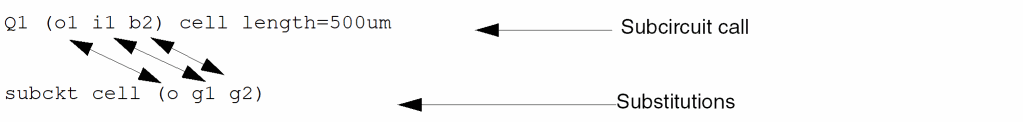
To call a subcircuit, place an instance statement in your netlist. The nodes for this instance statement are the connections to the subcircuit, and the master field in the subcircuit call contains the name of the subcircuit. You can enter parameters in a subcircuit call to override the parameters in the subcircuit definition for that subcircuit call.
The following example shows a subcircuit call and its corresponding subcircuit definition. cell is the name of the subcircuit being called; Q1 is the unique name of the subcircuit call; and o1, i1, and b2 are the connecting nodes to the subcircuit from the subcircuit call. When you call the subcircuit, the Spectre simulator substitutes these connecting node names in the subcircuit call for the connecting nodes in the subcircuit definition: o1 is substituted for o, i1 is substituted for g1, and b2 is substituted for g2. The length of transmission line TL is changed to 500 μm for this subcircuit call from its 355 μm default value in the subcircuit definition.
parameters length=355um
 TL   o    gnd  d    gnd  tline len=length vel=0.36
 Gt   d    g2   s         nGaAs
 Ctgd d    s              capacitor c=0.033p
 Cgg  g2   gnd            capacitor c=3p
 Gb   s    g1   gnd       nGaAs
 Cbgd s    gnd            capacitor c=0.033p
 Ro   d    c              resistor r=10k
 Co   c    gnd            capacitor c=0.165p
Modifying Subcircuit Parameter Values
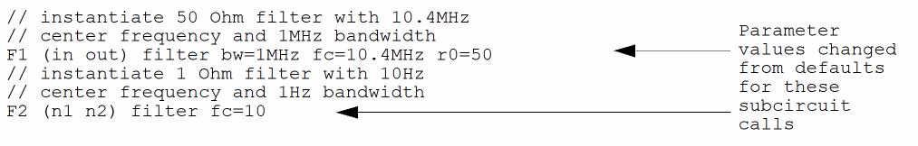
The following example is a passive Bessel three-pole bandpass filter with default parameter values for bandwidth, termination resistance, and center frequency. The bw, r0, and fc parameters are given default values in the subcircuit, but you can change these values when you call the subcircuit. Changing the value of bw, r0, and fc in a subcircuit call changes the values of many parameters in instance statements that refer to these three parameters.
// define passive 3-pole bandpass filter
subckt filter (n1 n2)
    parameters bw=1 r0=1 fc=1
    C1  (n1  0)   capacitor c=0.3374 / (6.2832 * bw * r0)
    L1  (n1  0)   inductor l=(r0 * bw) / (0.3374 * 6.2832 * fc * fc)
    C2  (n1  n12) capacitor c=bw / (0.9705 * 6.2832 * fc * fc * r0)
 L2  (n12 n2)  inductor l=(r0 * 0.9705) / (6.2832 * bw)
 C3  (n2  0)   capacitor c=2.2034 / (6.2832 * bw * r0)
 L3  (n2  0)   inductor l=(r0 * bw)/(2.2034 * 6.2832 * fc * fc)
ends filter
You can use such parameterized subcircuits when the Spectre simulator is reading either Spectre or SPICE syntax. Unlike subcircuit calls in SPICE, the names of Spectre subcircuit calls do not have to start with an x. This is useful if you want to replace individual components in an existing netlist with subcircuits for more detailed modeling.
Checking for Invalid Parameter Values
When you define subcircuits such as the one in Modifying Subcircuit Parameter Values, you might want to put error checking on the subcircuit parameter values. Such error checking prevents you from entering invalid parameter values for a given subcircuit call.
The Spectre paramtest component lets you test parameter values and generate necessary error, warning, and informational messages. For example, in the example of the bandpass filter in Modifying Subcircuit Parameter Values, the center frequency needs to be greater than half the bandwidth.
Here is a version of the previous three-pole filter that issues an error message if the center frequency is less than or equal to half the bandwidth:
* define passive 3-pole bandpass filter
subckt filter (n1 n2)
    parameters bw=1 r0=1 fc=1
  message="center frequency must be greater than half the
   bandwidth"
 C1  n1  0   capacitor c=0.3374 / (6.2832 * bw * r0)
 L1  n1  0   inductor l=(r0 * bw) / (0.3374 * 6.2832 * fc * fc)
 C2  n1  n12 capacitor   c=bw / (0.9705 * 6.2832 * fc * fc * r0)
 L2  n12 n2  inductor l=(r0 * 0.9705) / (6.2832 * bw)
 C3  n2  0   capacitor c=2.2034 / (6.2832 * bw * r0)
 L3  n2  0   inductor l=(r0 * bw) / (2.2034 * 6.2832 * fc * fc)
ends filter
The paramtest component checkFreqs has no terminals and no effect on the simulation results. It monitors its parameters and issues a message if a given condition is satisfied by evaluating to a nonzero number. In this case, errorif specifies that the Spectre simulator issues an error message and stops the simulation. If you specify printif, the Spectre simulator prints an informational message and continues the simulation. If you specify warnif, the Spectre simulator prints a warning and continues.
For more information about specific parameters available with the paramtest component, see the parameter listings in the Spectre online help (spectre -h).
Enabling/Disabling Noise in Subcircuits
You can enable or disable noise in subcircuit instances by using the global noiseon_inst and noiseoff_inst options or the isnoisy parameter.
noiseon_inst and noiseoff_inst options, if specified for the same instance, override the settings of the isnoisy parameter.
The isnoisy parameter can be specified in both subcircuit definitions and subcircuit instances. However, if the parameter is specified in both, the isnoisy parameter specified in the subcircuit instance gets higher priority. If the isnoisy parameter is also specified for a device instance, it gets the highest priority. In addition, if the isnoisy parameter is specified at different hierarchy levels, the parameter at the higher hierarchy level gets higher priority.
subckt sub1 a b
parameters isnoisy=no
r1 a b 1k
ends
X1 1 0 sub1 isnoisy=yes
X2 1 0 sub1
X3 1 0 sub1 isnoisy=no
In the above example, noise will be enabled in X1.
subckt sub1 a b
parameters isnoisy=no
X1 a 1 sub2 isnoisy=yes
X2 1 b sub2
ends
subckt sub2 a b
R1 a b 1K
ends
X1 1 0 sub1
In the above example, noise in X1.X1 will be enabled whereas noise in X1.X2 will be disabled.
subckt sub1 a b
parameters isnoisy=no
X1 a 1 sub2
X2 1 b sub3
ends
subckt sub2 a b
parameters isnoisy=yes
R1 a b 1K
ends
subckt sub3 a b
R1 a b 1K
ends
X1 1 0 sub1
In the above example, noise in X1.X1 will be enabled. Noise in X1.X2 will be disabled.
subckt sub1 a b
parameters isnoisy=no
R1 a 1 1K isnoisy=yes
R2 1 b 1K
ends
X1 1 0 sub1
In the above example noise will be enabled for X1.R1. It will be disabled for X1.R2.
The relation between noiseon_inst, noiseoff_inst, and isnoisy parameters for an instance (say X1) is shown below.
By default, all noise sources are enabled in all the devices in Spectre. The global noiseon_inst and noiseoff_inst options and the isnoisy parameter can only enable or disable all noise sources in a subcircuit instance. For example:
X1 a b c sub1
X2 a b c sub1
X3 a b c sub1
opt options noiseoff_inst=[X1]
In the above example, all noise sources in instance X1 are disabled and all noise sources in instances X2 and X3 are enabled.
You can use the global noiseon_type or noiseoff_type options to partially enable or disable the specific noise sources for a subcircuit instance. When you specify the noiseon_type option, it indicates that only the specified noise source is enabled and rest of the noise sources are disabled. Similarly, when you specify the noiseoff_type option, it indicates that only the specified noise source is disabled and rest of the noise sources are enabled.
Possible values for the noiseon_type and noiseoff_type options are thermal, flicker, shot, ign, and all.
X1 a b c sub1
X2 a b c sub1
X3 a b c sub1
opt1 options noiseoff_inst=[X1]
opt2 options noiseoff_type=[flicker]
In the above example, the flicker noise source in X1 is disabled. Rest of the noise sources in X1 are enabled. All noise sources in X2 and X3 are enabled.
X1 a b c sub1
X2 a b c sub1
X3 a b c sub1
opt1 options noiseoff_inst=[X1]
opt2 options noiseoff_type=[flicker]
opt3 options noiseon_type=[thermal]
In the above example, the flicker noise source in X1 is disabled. The rest of the noise sources in X1 are enabled. In addition, only the thermal noise source in X2 and X3 is enabled.The rest of the noise sources in X2 and X3 are disabled.
X1 a b c sub1
X2 a b c sub1
X3 a b c sub1
opt1 options noiseoff_type=[flicker]
opt2 options noiseon_type=[thermal]
In the above example, opt1 options will have no effect because no noise has been disabled using noiseon_inst, noiseoff_inst, or isnoisy. The thermal noise source will be enabled for the X1, X2, and X3 instances and rest of the noise sources will be disabled.
Conditional Subcircuits
You can specify different conditions that determine which subcircuits the Spectre simulator instantiates for a given simulation. The determining conditions are computed from the values of parameters. You specify these conditions with the structural if statement. This statement lets you specify if-else statements in the netlist.
You can also define a subcircuit in a file and include the file inside the conditional statement using the include statement.
Inline Subcircuits
An inline subcircuit is a special case where one of the instantiated devices or models within the subcircuit does not get its full hierarchical name but inherits the subcircuit call name. The inline subcircuit is called in the same manner as a regular subcircuit. You format inline subcircuit definitions as follows:
inline subcktSubcircuitName[(]node1...nodeN[)]
Depending on the use model, the body of the inline subcircuit typically contains one of the following:
-
Multiple device instances, one of which is the
inlinecomponent -
Multiple device instances (one of which is the
inlinecomponent) and one or more parameterized models -
A single
inlinedevice instance and a parameterized model to which the device instance refers - Only a single parameterized model
The inline component is denoted by giving it the same name as the inline subcircuit itself. When the subcircuit is flattened, as shown in the following section, the inline component does not acquire a hierarchical name such as X1.M1 but rather acquires the name of the subcircuit call itself, X1. Any noninline components in the subcircuit acquire the regular hierarchical name, just as if the concept of inline subcircuits never existed.
Typically, a modeling engineer writes inline subcircuit definitions for a circuit design engineer to use.
Modeling Parasitics
You can model parasitics by adding parasitics components to a base component using inline subcircuits. The body of the inline subcircuit contains one inline component, the base component, and several regular components, which are taken to represent parasitics.
The following example of an inline subcircuit contains a MOSFET instance and two parasitic capacitances:
inline subckt s1 (a b)           // "s1" is name of subcircuit
 parameters l=1u w=2u
 s1 (a b 0 0) mos_mod l=l w=w      // "s1" is "inline" component
 cap1 (a 0) capacitor c=1n
 cap2 (b 0) capacitor c=1n
ends s1
The following circuit creates a simple MOS device instanceM1and calls the inline subcircuits1twice (M2andM3):
M1 (2 1 0 0) mos_mod
M2(5 6) s1 l=6u w=7u
M3(6 7) s1
This circuit flattens to the following equivalent circuit:
M1 (2 1 0 0) mos_mod
M2 (5 6 0 0) mos_mod l=6u w=7u          // the "inline" component
       // inherits call name
M2.cap1 (5 0) capacitor c=1n          // a regular hierarchical name
M2.cap2 (6 0) capacitor c=1n
M3 (6 7 0 0) mos_mod l=1u w=2u          // the "inline" component
       // inherits call name
M3.cap1 (6 0) capacitor c=1n
M3.cap2 (7 0) capacitor c=1n
The final flattened names of each of the three MOSFET instances are M1, M2 and M3. (If s1 was a regular subcircuit, the final flattened names would be M1, M2.s1, and M3.s1.) However, the parasitic capacitors have full hierarchical names.
You can create an instance of the inline subcircuit cell in the same way as creating an instance of the specially tagged inline device. You can use save statements to probe this instance in the same way as a regular device, without having to
- Realize that the instance is actually embedded in a subcircuit
- Know that there are possible additional parasitic devices present
- Figure out the hierarchical name of the device of interest
A modeling engineer can create several of these inline subcircuits and place them in a library for the design engineer to use. The library then includes a symbol cell view for each inline subcircuit. The design engineer then places a symbol cell view on a design, which behaves just as if a primitive were being used. The design engineer can then probe the device for terminal currents and operating-point information.
Probing the Device
The Spectre simulator allows the following list of items to be saved or probed for primitive devices, including devices modeled as the inline components of inline subcircuits:
-
All terminal currents
save m1:currents
-
Specific (index) terminal current
save m1:1 //#1=drain
-
Specific (named) terminal current
save m1:s //"s"=source
-
Save all operating-point information
save m1:oppoint
-
Save specific operating-point information
save m1:vbe
-
Save all currents and operating-point information
save m1
Operating-point information for the inline component is reported with respect to the terminals of the inline component itself and not with respect to the enclosing subcircuit terminals. This results in the following cautions.
Caution: Parasitic Elements in Series with Device Terminals
If the parasitic elements are in series with the device terminals, the reported operating-point currents are correct, but reported operating-point voltages might be incorrect. For example, consider the case of an inline MOSFET device with parasitic source and drain resistances:
inline subckt mos_r (d g s b)
    parameters p1=1u p2=2u
    mos_r (dp g sp b) mos_mod l=p1 w=p2          // "inline" component
 rd (d dp) resistor r=10       // series drain resistance
 rs (s sp) resistor r=10       // series source resistance
ends mos_r
If an instance M1 is created of this mos_r inline subcircuit and the operating point of M1 is probed, the drain-to-source current ids is reported correctly. However, the reported vds is not the same as V(d) – V(s), the two wires that connect the subcircuit drain and source terminals. Instead, vds is V(dp) – V(sp), which are nodes internal to the inline subcircuit.
Caution: Parasitic Elements in Parallel with Device Terminals
If the parasitic elements are in parallel with the device terminals, the reported voltages are correct, but the reported currents might be incorrect. For example, consider the following case of a MOSFET with source-to-bulk and drain-to-bulk diodes:
inline subckt mos_d (d g s b)
    parameters p1=1u p2=2u
    mos_d (d g s b) mos_mod l=p1 w=p2              // "inline" component
 d1(d b) diode1 r=10       // drain-bulk diode
 d2(s b) diode1 r=10       // source-bulk diode
ends mos_d
Here, the operating-point vds for the inline component is reported correctly because there are no extra nodes introduced by the inline subcircuit model. However, the reported ids for the inline device is not the same as the current flowing into terminal d because some of the current flows into the transistor and some through diode d1.
Parameterized Models
Inline subcircuits can be used in the same way as regular subcircuits to implement parameterized models. When an inline subcircuit contains both a parameterized model and an inline device referencing that model, you can create instances of the device, and each instance automatically gets an appropriately scaled model assigned to it.
For example, the instance parameters of an inline subcircuit can represent emitter width and length of a BJT device. Within that subcircuit, a model statement can be created that is parameterized for emitter width and length and scales accordingly. When you instantiate the subcircuit, you supply the values for the emitter width and length, and the device is instantiated with an appropriate geometrically scaled model. Again, the inline device does not get a hierarchical name and can be probed in the same manner as if it were a simple device and not actually embedded in a subcircuit.
In the following example, a parameterized model is declared within an inline subcircuit for a bipolar transistor. The model parameters are the emitter width, emitter length, emitter area, and the temperature delta (trise) of the device above nominal. Ninety-nine instances of a 4x4 transistor are then placed, and one instance of a transistor with area=50 is placed. Each transistor gets an appropriately scaled model.
* declare a subcircuit, which instantiates a transistor with
* a parameterized model. The parameters are emitter width
* and length.

inline subckt bjtmod (c b e s)
    parameters le=1u we=2u area=le*we trise=0
    model mod1 bjt type=npn bf=100+(le+we)/2*(area/1e-12) \
             is=1e-12*(le/we)*(area/1e-12)
 bjtmod (c b e s) mod1 trise=trise        //"inline" component
ends bjtmod

* some instances of this subck
q1 (2 3 1 0) bjtmod le=4u we=4u            / trise defaults to zero
q2 (2 3 2 0) bjtmod le=4u we=4u trise=2
q3 (2 3 3 0) bjtmod le=4u we=4u
.
.
q99 (2 3 99 0) bjtmod le=4u we=4u
q100 (2 3 100 0) bjtmod le=1u area=50e-12
Since each device instance now gets its own unique model, this approach lends itself to statistical modeling of on-chip mismatch distributions, in which each device is taken to be slightly different than all the others on the same chip. The value of bf is the same for the first 99 transistors.
Inline Subcircuits Containing Only Inline model Statements
You can create an inline subcircuit that contains only a single model statement (and nothing else), where the model name is identical to the subcircuit name. This syntax is used to generate a parameterized model statement for a given set of parameters, where the model is then exported and can be referenced from one level outside the subcircuit. Instantiating the inline subcircuit in this case merely creates a model statement with the same name as the subcircuit call. The Spectre simulator knows that because the subcircuit definition contains only a model statement and no other instances, the definition is to be used to generate named models that can be accessed one level outside of the subcircuit. Regular device instances one level outside of the subcircuit can then refer to the generated model.
Because these are now instances of a model rather than of a subcircuit, you can specify device instance parameters with enumerated types such as region=fwd.
This technique is shown in the following example:
* declare an inline subcircuit that "exports" a parameterized model
inline subckt bjtmod
    parameters le=1u we=2u area=le*we
    model bjtmod bjt type=npn bf=100+(le+we)/2*(area/1e-12) \
             is=1e-12*(le/we)*(area/1e-12)
ends bjtmod

* now create two "instances" of the inline subcircuit, that is,
* create two actual models, called mod1, mod2

mod1 bjtmod le=4u we=4u
mod2 bjtmod le=1u area=50e-12

* 99 instances of mod1 (all share mod1)
* and 1 instance of mod2.
q1 (2 3 1 0) mod1 region=fwd
q2 (2 3 2 0) mod1 trise=2
.
.
q99 (2 3 99 0) mod1
q100 (2 3 100 0) mod2
Because the syntax of creating an instance of a model is the same as the syntax of creating an instance of a subcircuit in the Spectre netlist, you can easily replace model instances with more detailed subcircuit instances. To do this, replace the model statement itself with a subcircuit definition of the same name.
When you do this in the Spectre Netlist Language, you do not have to change the instance statements. In SPICE, inline subcircuits start with x, so you need to rename all instance statements to start with x if you replaced a model with a subcircuit.
Process Modeling Using Inline Subcircuits
Another modeling technique is to specify geometrical parameters, such as widths and lengths, to a device such as a bipolar transistor and then to create a parameterized model based on that geometry. In addition, the geometry can be modified according to certain process equations, allowing you to model nonideal etching effects, for example.
You use inline subcircuits and some include files for process and geometric modeling, as in the following example files. The ProcessSimple.h file defines the process parameters and the bipolar and resistor devices:
// File: ProcessSimple.h

simulator lang=spectre

// define process parameters, including mismatch effects

parameters RSHSP=200 RSHPI=5k // sheet resistance, pinched sheet res
+    SPDW=0 SNDW=0 // etching variation from ideal
+    XISN=1 XBFN=1 XRSP=1 // device "mismatch" (mm)
parameters
+    XISNafac=100m XISNbfac=1m // IS scaling factors for mm eqns
+     XBFNafac=100m XBFNbfac=1m    // BF "       "     "     "       "
+     XRSPafac=100m XRSPbfac=1m    // RS "       "     "     "       "
+     RSHSPnom=200 RSHPInom=5k     // sheet resistance nom. values
+     FRSHPI=RSHPI/RSHPInom        // ratio of PI sheet res to nom

// define "simple" bipolar and resistor devices

// a "base" TNSA subckt, that is, a simple "TNSA" bipolar transistor
//  subcircuit, with model statement
inline subckt TNSA_B (C B E S)
    parameters MULT=1 IS=1e-15 BF=100
    model modX bjt type=npn is=IS bf=BF   // a model statement
    TNSA_B (C B E S) modX m=MULT          // "inline" device instance
ends TNSA_B

// a "base" resistor
// a simple "RPLR" resistor subcircuit
inline subckt RPLR_B (A B)
    parameters R MULT=1
    RPLR_B (A B) resistor r=R m=MULT    // "inline" device
ends RPLR_B

// define process/geometry dependent bipolar and resistor devices

// a "geometrical/process" TNSA subcircuit
// a BJT subcircuit, with process and geometry effects modeled
// bipolar model parameters IS and BF are functions of effective
// emitter area/perimeter taking process factors (for example,
// nonideal etching) into account
inline subckt TNSA_PR (C B E S)
    parameters WE LE MULT=1 dIS=0 dBF=0
+            WEA=WE+SNDW    // effective or "Actual" emitter width
+            LEA=LE+SNDW    // effective or "Actual" emitter length
+            AE=WEA*LEA     // effective emitter area
+            IS=1e-18*FRSHPI*AE*(1+(XISNafac/sqrt(AE)+XISNbfac)
+                             *(dIS/2+XISN-1)/sqrt(MULT))
+            BF=100*FRSHPI*(1+(XBFNafac/sqrt(AE)+XBFNbfac)
+                             *(dBF/2+XBFN-1)/sqrt(MULT))

    TNSA_PR (C B E S) TNSA_B IS=IS BF=BF MULT=MULT        // "inline"
ends TNSA_PR

// a "geometrical/process" RPLR resistor subcircuit
// resistance is function of effective device geometry, taking
// process factors (for example, nonideal etching) into account
inline subckt RPLR_PR (A B)
    parameters Rnom WB MULT=1 dR=0
+            LB=Rnom*WB/RSHSPnom
+            AB=LB*(WB+SPDW)

    RPLR_PR (A B) RPLR_B R=RSHSP*LB/(WB+SPDW)*
+     (1+(XRSPafac/sqrt(AB)+XRSPbfac)*(dR/2+XRSP-1)/sqrt(MULT))

ends RPLR_PR
The following file, Plain.h, provides the designer with a plain device interface without geometrical or process modeling:
// File: Plain.h

simulator lang=spectre

// plain TNSA, no geometrical or process modeling
inline subckt TNSA (C B E S)
    parameters MULT=1 IS=1e-15 BF=100
    TNSA (C B E S) TNSA_B IS=IS BF=BF MULT=MULT       // call TNSA_B
ends TNSA

// plain RPLR no geometrical or process modeling
inline subckt RPLR (A B)
    parameters R=1 MULT=1
    RPLR (A B) RPLR_B R=R MULT=MULT
ends RPLR
The following file, Process.h, provides the designer with the geometrical device interface:
// File: Process.h

simulator lang=spectre

// call to the geometrical TNSA model
inline subckt TNSA (C B E S)
    parameters WE=1u LE=1u MULT=1 dIS=0 dBF=0
    TNSA (C B E S) TNSA_PR WE=WE LE=LE \
                 MULT=MULT dIS=dIS dBF=dBF      // call TNSA_PR
ends TNSA

// call to the geometrical RPLR model
inline subckt RPLR (A B)
    parameters Rnom=1 WB=10u MULT=1 dR=0
    RPLR (A B) RPLR_PR Rnom=Rnom WB=WB \
             MULT=MULT dR=dR                    // call RPLR_PR
ends RPLR
The following example is a differential amplifier netlist showing how a design can combine process modeling with process and geometry effects:
// a differential amplifier, biased with a 1mA current source
simulator lang=spectre

include "ProcessSimple.h"
include "Process.h"

E1 (1 0) vsource dc=12

// pullup resistors, 4k ohms nominal
R1 (1 2) RPLR Rnom=4k WB=5 // 5 units wide, model will calc length
R2 (1 3) RPLR Rnom=4k WB=10 // 10 units wide, model will calc length

// the input pair
TNSA1 (2 4 5 0) TNSA WE=10 LE=10
TNSA2 (3 4 5 0) TNSA WE=10 LE=10

// no differential input voltage, both inputs tied to same source
E4 (4 0) vsource dc=5

// current source biasing
J5 (5 0) isource dc=1m

dcop dc
Component Model
The component model is a special device modeling approach similar to the inline subckt model. However, unlike the inline subcircuit model, it does not use a separate device instance call inside the subcircuit but contains only the model definition. It allows you to separate the model parameters that are common to all the device instances and the device instance parameters. With this approach, it reduces the number of instance parameters that need to be stored for each device instance, and therefore provides optimized memory consumption and performance for advanced node device models. The component block can only be defined at the top level. It cannot be defined inside a subcircuit definition.
subckt p_svt_new ( d g s b )
parameters ...
p_svt_new ( d g s b ) p_svt_c w=w l=l ad=ad as=as pd=pd ps=ps sd=sd nf=nf nrd=nrd nrs=nrs dtemp=dtemp sca=sca ...
...
ends p_svt_new
component p_svt_c
parameters ...
model p_svt_c bsimbulk {
1: type=p
+vgs_max = 1.05 ... }
endcomponent p_svt_c
Model binning inside a component model is supported.
component nch
parameters paramtype=defined l = 3u w = 1u
model nch bsim4 {
1: type=n lmin=1u lmax=2u wmin=1u wmax=2u vth0=0.5
2: type=n lmin=2u lmax=4u wmin=2u wmax=4u vth0=0.4
3: type=n lmin=2u lmax=4u wmin=4u wmax=6u vth0=0.3
}
endcomponent
There are three types of parameters that can be defined inside the component block.
-
local parameters –
paramtype=local(default) -
instance parameters –
paramtype=instance -
local instance parameter –
paramtype=defined
The parameter types can be defined inside the component block using the paramtype keyword. The paramtype keyword has to be the first item after the parameters keyword. The default value of paramtype is local.
component p_svt_c
parameters paramtype=local param_local=12e-12 ...
parameters paramtype=instance param_instance=1e-9 ...
parameters paramtype=defined param_defined=43e-6 ...
...
model p_svt_c bsimbulk {
1: type=p
+vgs_max = 1.05 ... ab=param_local cd=param_instance ef=param_defined ... }
endcomponent p_svt_c
Binning
Binning is the process of partitioning a device with different sizes into different models. Before BSIM 3v3, it was very difficult to fit all the devices with a single model statement over very wide ranges of device sizes. To improve fitting accuracy, you might characterize devices into several models with each model valid only for a limited range of device sizes.
For example, suppose you have a device with a length (L) from 0.25 μm to 100 μm and a width (W) from 0.25 μm to 100 μm. You might want to divide your device as follows (not drawn to scale).
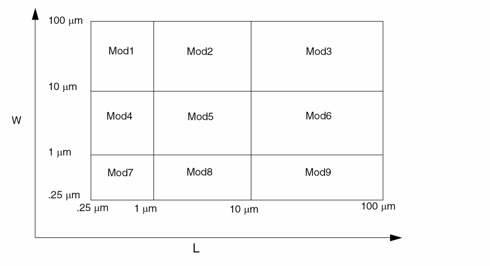
In this example, nine models are used. These devices are divided into bins. For devices whose length lies between 1 μm and 10 μm and width lies between 10 μm and 100 μm, Mod6 is used. The model name within a group can be of type string as well as a number.
The process of generating these models is called binning. The binning process is usually identical for all simulators because the equations for binning are always the same:
P = P0 + Pl/Leff + Pw/Weff + Pp/(Leff*Weff)
There are two ways to do binning with the Spectre simulator:
-
Auto model selection
For more information on auto model selection, see the following section. -
Conditional instances
For more information on using conditional instances, see Conditional Instances. For more information on using inline subcircuits for model selection, see Scaling Physical Dimensions of Components and Device Model Technology.
Auto Model Selection
Automatic model selection is a simulator feature that automatically assigns the correct models to devices based on their device sizes without using conditional instantiation.
Binning is usually used together with automatic model selection. Model selection is now automatic for MOSFETs, BSIM1, BSIM2, and BSIM3. Help on any one of these devices (for example, spectre -h mos1) gives you more details.
For the auto model selector program to find a specific model, the models to be searched need to be grouped together within braces. Such a group is called a model group. An opening brace is required at the end of the line defining each model group. Every model in the group is given a name followed by a colon and the list of parameters. Also, you need to specify the device length and width using the four geometric parameters lmax, lmin, wmax, and wmin. The selection criteria to choose a model is as follows:
lmin <= inst_length < lmaxandwmin <= inst_width < wmax
model ModelName ModelType {
    1:     lmin=2 lmax=4 wmin=1 wmax=2 vto=0.8
    2:     lmin=1 lmax=2 wmin=2 wmax=4 vto=0.7
    3:     lmin=2 lmax=4 wmin=4 wmax=6 vto=0.6
}
M1 1 2 3 4 ModelName w=3 l=1.5
the program searches all the models in the model group with the name ModelName and then picks the first model whose geometric range satisfies the selection criteria. In the preceding example, the auto model selector program chooses ModelName.2.
The following example shows multiple lines for each model statement within a group:
model pch mos2 {
    1:type=p vto=-0.65 gamma=0.47 lambda=0.09 \
     ld=0.45E-6 kp=0.33E-4 tox=0.21E-7 is=0.0 \
  lmin=0.5u lmax=1.5u wmin=1u wmax=3u \
  tnom=25 xl=3e-08 af=0.8824
 2:type=p vto=-0.69 gamma=0.44 lambda=0.09 \
  ld=0.45E-6 kp=0.33E-4 tox=0.21E-7 is=0.0 \
  lmin=1.5u lmax=2.5u wmin=3u wmax=5u
 3:type=p vto=-0.73 gamma=0.37 lambda=0.09 \
  ld=0.45E-6 kp=0.33E-4 tox=0.21E-7 is=0.0 \
  lmin=2.5u lmax=3.5u wmin=1u wmax=3u
 4:type=p vto=-0.77 gamma=0.34 lambda=0.09 \
  ld=0.45E-6 kp=0.33E-4 tox=0.21E-7 is=0.0 \
  lmin=3.5u lmax=4u wmin=3u wmax=5u
...
}
m0 (nd ng ns nb) pch m=1.0 w=4u l=2u
m1 (pd pg ps pb) pch m=1.0 w=4u l=4u
the auto model selector selects pch.2 for m0 and pch.4 for m1.
Conditional Instances
You can specify different conditions that determine which components the Spectre simulator instantiates for a given simulation. The determining conditions are computed from the values of parameters. You specify these conditions with the structural if statement. This statement lets you put if-else statements in the netlist.
You can also use conditional instantiation with inline subcircuits. For more information on using inline subcircuits, see Scaling Physical Dimensions of Components and Device Model Technology.
Formatting the if Statement
You format the structural if statement as follows:
ifconditionstatement1[elsestatement2]
An if Statement Example
The following example illustrates the use of the if statement. There are additional if statements in the statement1 and statement2 fields.
if (rseries == 0) {
    c1 (a b) capacitor c=c
    if (gparallel != 0) gp1 a b resistor r=1/gparallel
} else {
    r2 (a x) resistor r=rseries
    c2 (x b) capacitor c=c
    if (gparallel != 0) gp2 x b resistor r=1/gparallel
In this example, the Spectre simulator puts different instance statements into the simulation depending on the values of two parameters, rseries and gparallel.
-
If both
rseriesandgparallelare zero, the Spectre simulator includes the instance statement for capacitorc1.Ifrseriesis zero andgparallelis nonzero, the Spectre simulator includes the instance statements for capacitorc1and resistorgp1. -
If
rseriesis nonzero andgparallelis zero, the Spectre simulator includes the instance statements for resistorr2and capacitorc2. -
If neither
rseriesnorgparallelis zero, the Spectre simulator includes the instance statements for resistorr2, capacitorc2, and resistorgp2.
Rules to Remember
When you use the if statement,
-
If the statement1 or statement2 fields contain multiple statements, place these fields within braces (
{}). - End the statement1 and statement2 fields with newlines.
-
Use a continuation character if you want to place a newline between the
ifandconditionstatements. -
When the statement1 or statement2 field is a single instance or
ifstatement, anelsestatement is associated with the closest previousifstatement. -
Do not use the parameters specified with the
optionsstatement inside theifexpression, otherwise, you might get unexpected results. For example, do not use the following:simOptions options tnom=25
if (tnom == 27) { //27 is the default value of tnom
r1 0 1 resistor r=10
} else {
r1 0 1 resistor r=20
}
Binning by Conditional Instantiation
You can use conditional instantiation to select an appropriate model based on certain ranges of specified parameters (model binning). This technique lets you decide and implement which parameters to bin on and is valid for any device that supports a model.
The Spectre Netlist Language has conditional instantiation. For example:
subckt s1 (d g s b)
    parameters l=1u w=1u
    if (l < 0.5u) {
     m1 (d g s b) shortmod l=l w=w             // short-channel model
 } else {
  m2 (d g s b) longmod l=l w=w            // long-channel model
 }
 model shortmod vto=0.6 gamma=2 ..etc
 model longmod vto=0.8 gamma=66 ..etc
ends s1
Based on the value of parameter l, one of the following is chosen:
Previously, the transistor instances had to have unique names (such as m1 and m2 in the preceding example), even though only one of them could actually be chosen. Now, you can use the same name for both instances, provided certain conditions are met. The following example shows a powerful modeling approach that combines model binning (based on area) with inline subcircuits for a bipolar device:
// general purpose binning and inline models

simulator lang=spectre
parameters VDD=5

vcc (2 0) vsource dc=VDD
vin (1 0) vsource dc=VDD

q1 (1 2 0 0) npn_mod area=350e-12         // gets 20x20 scaled model
q2 (1 3 0 0) npn_mod area=25e-12          // gets 10x10 scaled model
q3 (1 3 0 0) npn_mod area=1000e-12        // gets default model

inline subckt npn_mod (c b e s) //generalized binning, based on area
    parameters area=5e-12
    if ( area < 100e-12 ) {
     npn_mod (c b e s) npn10x10  // 10u * 10u, inline device
 } else if ( area < 400e-12 ) {
  npn_mod (c b e s) npn20x20  // 20u * 20u, inline device
 } else {
  npn_mod (c b e s) npn_default       // 5u * 5u, inline device
 }
 model npn_default bjt is=3.2e-16 va=59.8
 model npn10x10 bjt is=3.5e-16 va=61.5
 model npn20x20 bjt is=3.77e-16 va=60.5
ends npn_mod
The transistors end up having the name that they were called with (q1, q2, and q3), but each has the correct model chosen for its respective area. Model binning can be now achieved based on any parameter and for any device, such as resistor or bjt.
Changing the Condition Value In Conditional Instantiation
Changing the value of a parameter that results in a change of boolean if condition value is allowed only if there is no actual topology change and the following conditions are met:
-
The number of instances in the
ifandelseblocks are the same. -
The names of the instances in the
ifandelseblocks are the same. -
Corresponding instances (with the same name) in the
ifandelseblocks are instances of the same model or sub-circuit, or instances of two different models of the same primitive type.
For example, you can do the following:
model mos1 bsim3v3  <model-params-1>
model mos2 bsim3v3  <model-params-2>
model mos3 bsim3v3  <model-params-3>
if  (p<=1)
    m1 1 1 0 0 mos1
else if (p<=2)
    m1 1 1 0 0 mos2
else
    m1 1 1 0 0 mos3
sweep1 sweep param=p values=[1 2 3]
The following example does not satisfy the second condition above, so the Spectre simulator errors out even though there is no actual topology change:
parameters p=1
if (p<=1)
    r1 1 0 resistor r=1K
else
    r2 1 0 resistor r=10K
al1 alter param=p value=2
Rules for General-Purpose Model Binning
The following set of rules exists for general-purpose model binning. Allowing multiple “instances” or “references” to the same-named device is possible only under the following conditions:
-
The reference to the same-named device is possible only in a structural
ifstatement that has both anifpart and anelsepart. - The conditions of the if statements must evaluate to a single device instance with a unique name in that scope.
Multiple references to the same-named device are only possible if there can only ever be one single instance of this device after all expressions have been evaluated, and each instance must be connected to the same nodes and represent the same device.
Examples of Conditional Instances
The following two examples show how to use conditional instances.
Fully Differential CMOS Operational Amplifier
This netlist describes and analyzes a CMOS operational amplifier and demonstrates several sophisticated uses of Spectre features. The example includes top-level netlist parameters, model library/section statements, multiple analyses, and configuring a test circuit with the alter statement.
The first file in the example is the main file for the circuit. This file contains the test circuit and the analyses needed to measure the important characteristics of the amplifier.
The main file is followed by files that describe the amplifier and the various models that can be selected. These additional files are placed in the netlist with include statements.
Voltage-controlled voltage sources transform single-ended signals to differential- and common-mode signals and vice versa. This approach does not generate or dissipate any power. The power dissipation reported by the Spectre simulator is that of the differential amplifier.
// Fully Differential Operational Amplifier Test Circuit
#define PROCESS_CORNER TYPICAL
simulator lang=spectre
global gnd vdd vss
parameters VDD=5.0_V GAIN=0.5
include "cmos.mod"      section=typical
include "opamp.ckt"
// power supplies
Vdd   (vdd   gnd)   vsource dc=VDD
Vss   (vss   gnd)   vsource dc=-VDD
// compute differential input
Vcm   (cmin  gnd)   vsource type=dc dc=0 val0=0 val1=2 width=1u \
        delay=10ns
Vdif  (in    gnd)   vsource type=dc dc=0 val0=0 val1=2 width=1u \
        delay=10ns
Ridif (in    gnd)   resistor
Eicmp (pin   cmin  in    gnd)   vcvs gain=GAIN
Eicmn (nin   cmin  in    gnd)   vcvs gain=-GAIN
// feedback amplifier
A1    (pout  nout  pvg        nvg)    opamp
Cf1   (pout  t1)    capacitor  c=8p
Cf2   (nout  t2)    capacitor  c=8p
Vt1   (t1    nvg)   vsource    mag=0
Vt2   (t2    pvg)   vsource    mag=0
Cl1   (pout  gnd)   capacitor  c=8p
Cl2   (out  gnd)    capacitor  c=8p
Ci1   (pin   pvg)   capacitor  c=2p
Ci2   (nin   nvg)   capacitor  c=2p
// compute differential output
Edif  (out   gnd   pout  nout) vcvs gain=1
Rodif (out   gnd)  resistor
Ecmp  (cmout mid   pout  gnd) vcvs gain=GAIN
Ecmn  (mid   gnd   nout  gnd) vcvs gain=GAIN
Rocm  (cmout gnd)  resistor
//
// Perform measurements
//
spectre options save=lvlpub nestlvl=1
printParams info what=output where=logfile
// operating point
opPoint dc readns="%C:r.dc" write="%C:r.dc"
printOpPoint info what=oppoint where=logfile
// differential-mode characteristics
      // closed-loop gain, Av = Vdif:p
       // power supply rejection ratio, Vdd PSR = Vdd:p, Vss PSR = Vss:p
      dmXferFunctions xf start=1k stop=1G dec=10 probe=Rodif
dmNoise noise start=1k stop=1G dec=10 \
        oprobe=Edif oportv=1 iprobe=Vdif iportv=1
// step response
dmEnablePulse alter dev=Vdif param=type value=pulse annotate=no
dmStepResponse tran stop=2us errpreset=conservative
dmDisablePulse alter dev=Vdif param=type value=dc annotate=no
// loop gain, Tv = -t1/nvg
// open-loop gain, av = out/(pvg-nvg)
dmEnableTest1 alter dev=Vt1 param=mag value=1 annotate=no
dmEnableTest2 alter dev=Vt2 param=mag value=-1 annotate=no
dmLoopGain ac start=1k stop=1G dec=10
dmDisableTest1 alter dev=Vt1 param=mag value=0 annotate=no
dmDisableTest2 alter dev=Vt2 param=mag value=0 annotate=no
// common-mode characteristics
      // closed-loop gain, Av = Vcm:p
       // power supply rejection ratio, Vdd PSR = Vdd:p, Vss PSR =Vss:p
      cmXferFunctions xf start=1k stop=1G dec=10 probe=Rocm
      cmNoise noise start=1k stop=1G dec=10 \
                oprobe=Rocm oportv=1 iprobe=Vcm iportv=1
// step response
cmEnablePulse alter dev=Vcm param=type value=pulse annotate=no
cmStepResponse tran stop=2us errpreset=conservative
cmDisablePulse alter dev=Vcm param=type value=dc annotate=no
// loop gain, Tv = -t1/nvg
// open-loop gain, av = 2*cmout/(pvg+nvg)
cmEnableTest1 alter dev=Vt1 param=mag value=1 annotate=no
cmEnableTest2 alter dev=Vt2 param=mag value=1 annotate=no
cmLoopGain ac start=1k stop=1G dec=10
cmDisableTest1 alter dev=Vt1 param=mag value=0 annotate=no
cmDisableTest2 alter dev=Vt2 param=mag value=0 annotate=no
The following file, opamp.ckt, contains the differential amplifier.
// opamp.ckt: Fully Differential CMOS Operational Amplifier
//
// This circuit requires the use of the cmos process models
simulator lang=spectre
// Folded-Cascode Operational Amplifier
subckt opamp (pout nout pin nin)
        // input differential pair
        M1   (4    pin  1    1)    nmos w=402.4u l=7.6u
        M2   (5    nin  1    1)    nmos w=402.4u l=7.6u
        M18  (1   12   vss  vss)   nmos w=242.4u l=7.6u
// upper half of folded cascode
        M3   (4    11   vdd  vdd)  pmos w=402.4u l=7.6u
        M4   (5    11   vdd  vdd)  pmos w=402.4u l=7.6u
        M5   (nout 16   4    vdd)  pmos w=122.4u l=7.6u
        M6   (pout 16   5    vdd)  pmos w=122.4u l=7.6u
// lower half of folded cascode
        M7   (nout 13   8    vss)  nmos w=72.4u l=7.6u
        M8   (pout 13   9    vss)  nmos w=72.4u l=7.6u
        M9   (8    12   vss  vss)  nmos w=122.4u l=7.6u
        M10  (9    12   vss  vss)  nmos w=122.4u l=7.6u
// common-mode feedback amplifier
        M11  (10   nout vss  vss)  nmos w=12.4u l=62.6u
        M12  (10   pout vss  vss)  nmos w=12.4u l=62.6u
        M13a (11   gnd  vss  vss)  nmos w=12.4u l=62.6u
        M13b (11   gnd  vss  vss)  nmos w=12.4u l=62.6u
        M14  (10   10   vdd  vdd)  pmos w=52.4u l=7.6u
        M15  (11   10   vdd  vdd)  pmos w=52.4u l=7.6u
        Cc1  (nout 11)   capacitor c=1p
        Cc2  (pout 11)  capacitor c=1p
// bias network
        M16  (12   12   vss  vss)  nmos w=22.4u l=11.6u
        M17  (21   12   vss  vss)  nmos w=22.4u l=11.6u
        M19  (13   13   14   vss)  nmos w=22.4u l=21.6u
        M20  (13   21   16   vdd)  pmos w=52.4u l=7.6u
        M21  (21   16   17   vdd)  pmos w=26.4u l=11.6u
        M22  (16   16  17    vdd)  pmos w=26.4u l=11.6u
        D1   (15   vss)  dnp area=400n
        D2   (14   15)   dnp area=400n
        D3   (18   17)   dnp area=400n
        D4   (vdd  18)   dnp area=400n
        Ib   (gnd  12)   isource dc=10u
ends opamp
The following file, cmos.mod, contains the models and uses the library and section statements to bin models into various process “corners.” See Process File for a more sophisticated example, which also includes automatic model selection.
// cmos.mod: Spectre MOSFET model parameters  ---  CMOS process
//
// Empirical parameters, best, typical, and worst cases.
//
//
simulator lang=spectre
library cmos_mod
  section fast // MOSFETS and DIODES for process corner "FAST"
    model nmos mos3 type=n vto=1.04 gamma=1.34 phi=.55 nsub=1e15 \
            cgso=290p cgdo=290p cgbo=250p cj=360u tox=700e-10 \
                    pb=0.914 js=1e-4 xj=1.2u ld=1.2u wd=0.9u uo=793 bvj=14
     model pmos mos3 type=p vto=-0.79 gamma=0.2 phi=.71 nsub=1.7e16\
            cgso=140p cgdo=140p cgbo=250p cj=80u tox=700e-10 \
                    pb=0.605 js=1e-4 xj=0.8u ld=0.9u wd=0.9u uo=245 bvj=14
     model dnp diode is=3.1e-10 n=1.12 cjo=3.1e-8 pb=.914 m=.5 bvj=45 \
            imax=1000
     model dpn diode is=1.3e-10 n=1.05 cjo=9.8e-9 pb=.605 m=.5 bvj=45 \
            imax=1000
  endsection fast
  section typical // MOSFETS and DIODES for process corner "TYPICAL"
    model nmos mos3 type=n vto=1.26 gamma=1.62 phi=.58 nsub=1e15 \
          cgso=370p cgdo=370p cgbo=250p cj=400u tox=750e-10 \
                      pb=0.914 js=1e-4 xj=1u ld=0.8u wd=1.2u uo=717 bvj=14
      model pmos mos3 type=p vto=-1.11 gamma=0.39 phi=.72 nsub=1.7e16 \
          cgso=220p cgdo=220p cgbo=250p cj=100u tox=750e-10 \
                  pb=0.605 js=1e-4 xj=0.65u ld=0.5u wd=1.2u uo=206 bvj=14
     model dnp diode is=3.1e-10 n=1.12 cjo=3.1e-8 pb=.914 m=.5 bvj=45 \
           imax=1000
     model dpn diode is=1.3e-10 n=1.05 cjo=9.8e-9 pb=.605 m=.5 bvj=45 \
           imax=1000
  endsection typical
  section slow // MOSFETS and DIODES for process corner "SLOW"
    model nmos mos3 type=n vto=1.48 gamma=1.90 phi=.59 nsub=1e15 \
          cgso=440p cgdo=440p cgbo=250p cj=440u tox=800e-10 \
                  pb=0.914 js=1e-4 xj=0.8u ld=0.38u wd=1.5u uo=641 bvj=14
      model pmos mos3 type=p vto=-1.42 gamma=0.58 phi=.73 nsub=1.7e16 \
          cgso=300p cgdo=300p cgbo=250p cj=120u tox=800e-10 \
                    pb=0.605 js=1e-4 xj=0.5u ld=0.1u wd=1.5u uo=167 bvj=14
     model dnp diode is=3.1e-10 n=1.12 cjo=3.1e-8 pb=.914 m=.5 bvj=45 \
           imax=1000
     model dpn diode is=1.3e-10 n=1.05 cjo=9.8e-9 pb=.605 m=.5 bvj=45 \
           imax=1000
  endsection slow
endlibrary
Process File
This example of automatic model selection with the conditional if statement is more sophisticated than the previous example (in section Fully Differential CMOS Operational Amplifier). With this example, you ask for an nmos transistor, and the Spectre simulator automatically selects the appropriate model according to the process corner, the circuit temperature, and the device width and length. The selection is done by the parameterized inline subcircuit and the conditional if statement.
The paramtest statements create warnings if the model selection parameters are out of range. Models are assigned to instances depending on the initial values of their parameters when the circuit is input. Note that the instances are not reassigned to new models if the selection parameters later change. However, the models are updated if the circuit temperature is changed. Notice that even though nmos is defined as a subcircuit, it is called as if it is a MOSFET primitive.
The MOSFET model parameters are deleted to keep this example to a reasonable length, and ordinarily both the N- and P-channel models are in the same file. If you added the model parameters and a pmos model, this file could replace cmos.mod in the previous example.
// N-CHANNEL MOS --- 1u NMOS PROCESS
//
//
// The following group of models represent N-channel MOSFETs over
// the following ranges:
//     1u <= l <= oo
//     1u <= w <= oo
//     0 <= T <= 55
//     process corners = {FAST, TYPICAL, SLOW}
// Warnings are issued if these limits are violated.
//
// This model takes 4 parameters, l, w, ls, and ld.  The defaults for
// each of these parameters is 1um.
//
//              +-----------+
//     +--------+           +--------+ ---
//     |        |           |        |  ^
//     |        |           |        |  |
//     |<- ls ->|<--- l --->|<- ld ->|  w
//     |        |           |        |  |
//     |        |           |        |  v
//     +--------+           +--------+ ---
//              +-----------+
//       Source      Gate       Drain
//
simulator lang=spectre
//
// Complain if global constants are out-of-range.
//
TooCold paramtest warnif=(temp < 0) \
        message="The nmos model is not accurate below 0 C."
TooHot paramtest warnif=(temp > 55) \
        message="The nmos model is not accurate above 55 C."
//
// Define inline subcircuit that implements automatic model selection
// this uses user-supplied parameters l and w which represent device
// geometry, and the built-in parameter temp, to perform model binning
// based on both geometry and temperature.
//
inline subckt nmos (d g s b)
        parameters l=1um w=1um ls=1um ld=1um
//
// Complain if subcircuit parameters are out-of-range.
//
TooShort paramtest warnif=(l < 1um) \
        message="Channel length for nmos must be greater than 1u."
TooThin paramtest warnif=(w < 1um) \
        message="Channel width for nmos must be greater than 1u."
TooNarrow paramtest warnif=(ls < 1um) warnif=(ld < 1um) \
        message="Stripe width for nmos must be greater than 1u."
//
// Model selection
include "models.scs"                      // include all model definitions
include "select_model.scs " section=typical // include code to auto
// choose models
ends nmos
//
// Set the temperature
//
nmosSetTempTo27C alter param=temp value=27
The following file, models.scs, contains the models, which depend on circuit temperature (temp). Each model parameter can take on one of two values, depending on the value of parameter temp.
//
// Fast models.
//
model fast_1x1 mos3 type=n vto=(temp >= 27_C) ? 0.8 : 0.77   // ...etc
model fast_1x3 mos3 type=n vto=(temp >= 27_C) ? 0.9 : 0.78   // ...etc
model fast_3x1 mos3 type=n vto=(temp >= 27_C) ? 0.95 : 0.79  // ...etc
model fast_3x3 mos3 type=n vto=(temp >= 27_C) ? 0.98 : 0.81  // ...etc
//
// Typical models.
//
model typ_1x1 mos3 type=n vto=(temp >= 27_C) ? 0.90 : 0.75   // ...etc
model typ_1x3 mos3 type=n vto=(temp >= 27_C) ? 0.91 : 0.73   // ...etc
model typ_3x1 mos3 type=n vto=(temp >= 27_C) ? 0.97 : 0.77   // ...etc
model typ_3x3 mos3 type=n vto=(temp >= 27_C) ? 0.99 : 0.84   // ...etc
//
// Slow models.
//
model slow_1x1 mos3 type=n vto=(temp >= 27_C) ? 0.92 : 0.76  // ...etc
model slow_1x3 mos3 type=n vto=(temp >= 27_C) ? 0.93 : 0.74  // ...etc
model slow_3x1 mos3 type=n vto=(temp >= 27_C) ? 0.98 : 0.78  // ...etc
model slow_3x3 mos3 type=n vto=(temp >= 27_C) ? 0.98 : 0.89  // ...etc
The following file, select_models.scs, uses the structural if statement to select models based on parameters l and w. Note that for MOS devices, this could also be achieved by using auto model selection (see spectre -h mos3), but this example illustrates model binning and model selection based on the structural if statement, which can be used to bin based on any combination of parameters, (not necessarily predefined device geometry models) and for any device type (that is, not limited to MOS devices only).
library select_models
section fast // select models for fast device, based on subckt
//parameters l,w
    if (l <= 3um) {
        if (w <= 3um) {
             nmos (d g s b) fast_1x1 l=l w=w ls=ls ld=ld
        } else {
             nmos (d g s b) fast_1x3 l=l w=w ls=ls ld=ld
        }
    } else {
        if (w <= 3um) {
             nmos (d g s b) fast_3x1 l=l w=w ls=ls ld=ld
        } else {
             nmos (d g s b) fast_3x3 l=l w=w ls=ls ld=ld
        }
    }
endsection fast
section typical
    if (l <= 3um) {
        if (w <= 3um) {
             nmos (d g s b) typ_1x1 l=l w=w ls=ls ld=ld
        } else {
             nmos (d g s b) typ_1x3 l=l w=w ls=ls ld=ld
        }
    } else {
        if (w <= 3um) {
             nmos (d g s b) typ_3x1 l=l w=w ls=ls ld=ld
        } else {
             nmos (d g s b) typ_3x3 l=l w=w ls=ls ld=ld
        }
    }
endsection typical
section slow
    if (l <= 3um) {
        if (w <= 3um) {
             nmos (d g s b) slow_1x1 l=l w=w ls=ls ld=ld
        } else {
             nmos (d g s b) slow_1x3 l=l w=w ls=ls ld=ld
        }
    } else {
        if (w <= 3um) {
             nmos (d g s b) slow_3x1 l=l w=w ls=ls ld=ld
        } else {
             nmos (d g s b) slow_3x3 l=l w=w ls=ls ld=ld
        }
    }
endsection slow
endlibrary
Scaling Physical Dimensions of Components and Device Model Technology
Selected components allow their physical dimensions to be scaled with global scale factors. When you want to scale the physical dimensions of these instances and models, you use the scale and scalem parameters in the options statement. Use scale for instances and scalem for models. The default value for both scale and scalem is 1.0. (For more information about the options statement, see options Statement Format and the documentation for the options statement in Spectre online help spectre .)
-h options
You can scale the following devices with scale and scalem:
-
Capacitors—length (
l) or width (w) -
Diodes—length (
l) or width (w) -
Resistors—length (
l) or width (w) -
Physical resistors (
phy_res)—length (l) or width (w) - MOSFET—length or width
Finding Default Measurement Units
The effects of scale and scalem depend on the default measurement units of the components you scale. To find the default measurement units for a component parameter, look up that parameter in the parameter listings of your Spectre online help (spectre -h). The default for measurement units is in parentheses. For example, the (m) in this entry from the mos8 parameter descriptions in the Spectre online help (spectre -h) tells you that the default measurement unit for channel width is meters.
w (m) Channel width
Effects of scale and scalem with Different Default Units
scale and scalem affect only parameters whose default measurement units are in meters. For example, vmax is affected because its units are m/sec, but ucrit is not affected because its units are V/cm. Similarly, nsub is not affected because its units are 1/cm3. You can check the effects of scale and scalem by adding an info statement with what=output and look for the effective length (leff) or width (weff) of a device. For more information about the info statement, see The info Statement.
The following table shows you the effects of scale and scalem with different units:
| scale or scalem | Units | Scaling action |
|---|---|---|
Scaling Device Model Technology
The scalefactor parameter in the options statement enables device model providers to scale device technology independent of the design dimension scaling done by circuit designers. The resulting device instance scaling is defined by scale * scalefactor. If the foundry uses a technology scale factor of 0.9 (scalefactor=0.9), and the circuit designer uses a design scale factor of 1e-6 (scale=1e-6), then the compounded scaling of the device instance dimension is 0.9e-6. Unlike the scale parameter, the scalefactor parameter cannot be used as a netlist parameter and cannot be altered or used in sweep statements.
String Parameters
You can use quoted character strings as parameter values. String values you might use as Spectre parameter values include filenames and labels. When you use a string as a parameter, enclose the string in quotation marks. In the following example, the value for the parameter named file is the character string Spara.data.
model sp_data nport file="Spara.data"
Multi-Technology Simulation
The Spectre circuit simulator supports a multi-technology simulation (MTS) mode that enables the simulation of a system consisting of blocks designed with different processes. Under this mode, models and modelgroups referenced using include or ahdl_include statements in a subcircuit are locally scoped to that subcircuit only. In addition, process options parameters (temp, tnom, scale, and scalem), when specified in a subcircuit, are locally scoped to that subcircuit only.
MTS mode is enabled by default across all Spectre simulators. To turn the MTS mode off, use the -mts command-line option.
Here is an example of a system consisting of blocks designed with different processes:
globaloptions options tnom=26 scale=1
subckt chip1 ( in out )
     ahdl_include "a.va"
 include "pmos_mode.scs"
 scopedoption1 options tnom=27 scale=0.1
 subckt inv ( in out )
 mp ( out in vdd vdd ) pmos w=1u l=3u
 mn ( out in 0 0 ) nmos w=1u l=3u
 ends inv
 subckt buffer ( in out )
 x1 ( in mid ) inv
 x2 ( mid out ) inv
 ends buffer
 xa ( in out ) buffer
 model nmos bsim3v3 type=n
ends chip1
subckt chip2 ( in out )
    ahdl_include "b.va"
    scopedoption2 options tnom=25 scale=0.2
    subckt inv ( in out )
    mp ( out in vdd vdd ) pmos w=1u l=3u
    mn ( out in 0 0 ) nmos w=1u l=3u
    ends inv
    subckt buffer ( in out )
    x1 ( in mid ) inv
    x2 ( mid out ) inv
    ends buffer
    xa ( in out ) buffer
    model pmos bsim3v3 type=p
    model nmos bsim3v3 type=n
ends chip2
In the log file, you will see the following user options:
Global user options:
tnom = 26
scale = 1
Scoped user options:
tnom = 27 subckt=chip1
scale = 0.1 subckt=chip1
tnom = 25 subckt=chip2
scale = 0.2 subckt=chip2
You may disable some of the instances and subcircuits by using the skip option with the scope specified for MTS. For example,
Opt1 options skip=cut inst=[x1 x2]
Opt1 options skip=cut subckt=[sub1 sub2]
The possible values for the skip option are none, load, and cut. The default value is none. When you set the skip option to cut, the simulator leaves the instance terminals or subcircuit ports disconnected, when MTS is enabled.
Specifying cmin
By default, the Spectre circuit simulator considers all options specified for a node as global options, and all nodes in the design share the same options. However, you can use cmin as a scoped option or with the node statement and use this capability to apply this option to the nodes in a certain scope to aid convergence.
Specifying cmin as a scoped option
You can specify cmin as a scoped option, as shown in the following examples:
Opt1 options cmin=0.001 sub=[sub1]
Here, the cmin value 0.001 will be applied to all nodes of the subcircuit instances whose master is sub1
Opt2 options cmin=0.002 inst=[x1]
Here, the cmin value 0.002 will be applied to all nodes of the subcircuit instance X1.
The supported scope types for the cmin option are: sub/subckt and dev/inst.
The scoped options are displayed under the Scoped user options section in the Spectre log file, as shown below.
Scoped user options:
cmin = 0.001 sub=sub1
Specifying cmin with the node Statement
You can specify cmin with the node statement, as shown below.
Node1 (n1) node cmin=0
In the above example, the cmin value on node n1 will be 0.
node1 (n1) node cmin=0 sub=[sub1 sub2 ..]
In the above example, cmin=0 is applied to the internal node or port with the name n1 for subcircuit instances whose master is sub1 or sub2.
cmin both as a scoped option and in the node statement. However, if there is a conflict, the cmin option specified in the node statement gets higher precedence than the scoped cmin option. If there is no conflict, their scope is merged.Return to top