You can simulate designs that contain SystemVerilog modules together with Verilog-AMS and VHDL-AMS modules. The following are the guidelines to follow in mixed-signal designs containing SystemVerilog and AMS modules:
- You may use either single-step simulation method to run a design with SystemVerilog and AMS blocks. When you use the
xruncommand, SystemVerilog and AMS parts of the design must be in separate files with appropriate file suffixes indicating design unit syntax (such as.svfor SystemVerilog and.vamsfor Verilog-AMS).
- Block Discipline Resolution (BDR) takes place whenever the
-svor +svoption is used on thexruncommand line for any combination of Verilog, SystemVerilog or pure Verilog net connections.
- The SystemVerilog scope must not contain any explicitly declared electrical nets. However, nets in the SystemVerilog scope may become electrical using discipline resolution if connected to an electrical port.
- Any out-of-module reference (OOMR) to a SystemVerilog item from a Verilog-AMS or VHDL-AMS scope can only reference the types that can be used in hierarchical connections between the two languages.
- SystemVerilog and AMS blocks can be connected using the SystemVerilog real or logic variable data type in the following design configurations:
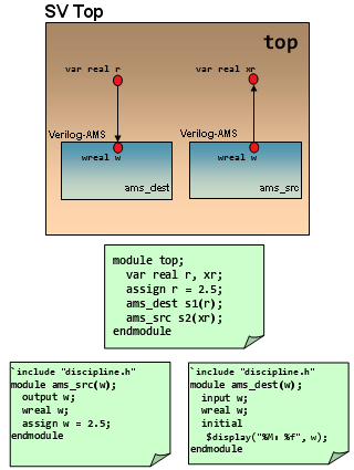
- SystemVerilog on top instantiating Verilog-AMS: In this configuration, a real or logic variable in the SystemVerilog scope can connect to an electrical, wreal port of the Verilog-AMS block below, or a SPICE port. If the electrical or SPICE ports are an output port, it is fully supported. However, if the lower connection is an input port or an inout port, then the simulator generates an error. See the SystemVerilog on top instantiating Verilog-AMS: electrical port in Verilog-AMS and SystemVerilog on top instantiating Verilog-AMS: wreal port in Verilog-AMS figures.
Figure 19.1: SystemVerilog on top instantiating Verilog-AMS: electrical port in Verilog-AMS
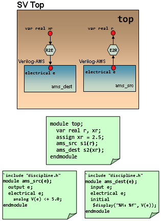
Figure 19.2: SystemVerilog on top instantiating Verilog-AMS: wreal port in Verilog-AMS
Power-smart Interface Elements (IEs) are supported to connect SystemVerilog real variable data type to Verilog or Verilog-AMS logic signal.
- Verilog-AMS on top instantiating SystemVerilog: In this configuration, an
electricalorwrealport of the Verilog-AMS block can connect to arealvariable in the SystemVerilog scope. If the port of the Verilog-AMS block is ofwrealtype, a connection is established with the SystemVerilogrealvariable without the need for any connection module (See the Verilog-AMS on top instantiating SystemVerilog: wreal port in Verilog-AMS figure).
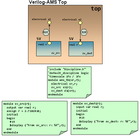
If the port of the Verilog-AMS block is ofelectricaltype, a connection is established with the SystemVerilogrealvariable by including an Electrical-To-Real connect module. (See the Verilog-AMS on top instantiating SystemVerilog: electrical port in Verilog-AMS figure).
Figure 19.3: Verilog-AMS on top instantiating SystemVerilog: wreal port in Verilog-AMS
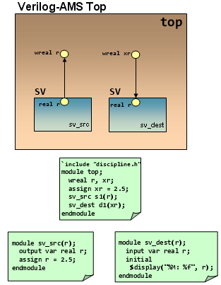
Figure 19.4: Verilog-AMS on top instantiating SystemVerilog: electrical port in Verilog-AMS
- Additionally, those hierarchical connections are allowed between SystemVerilog and Verilog-AMS, which are currently supported by the AMS Designer simulator between existing Verilog-2001 and Verilog-AMS data objects.
The following SPICE units are not recognized by SystemVerilog:
- Built-in primitives such as resistor, capacitor, or MOSFET
- Primitives brought in through CMI libraries
- Primitives brought in using the
MODELPATHoption
If the tool encounters such a primitive, it searches for a regular master of the same name; and when the master is not found, the elaboration step exits with an error.
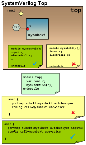
- A SPICE subckt can be instantiated in SystemVerilog with restriction if the connection is made using the SystemVerilog real variable. In such a scenario, the direction of each port of the subckt must be clearly specified as either input or output by using any of the following three ways:
- By using the
reffileoption on the AMS control blockportmapcard. This points back to the original Verilog-AMS file from which the port directions are taken. - By using an
inputoroutputoption on the port in question on the AMS control blockportmapcard. - By using a
fileoption for a port bind file specified on the AMS control blockportmapcard. This port bind file contains explicit instructions for mapping the SPICE ports to the ports in the generated skeleton. These instructions can include port directions. Each port of the subckt must be clearly designated.The reason for this restriction is that the SystemVerilog real variable can only support a single driver, and therefore cannot be connected to bidirectional (inout) ports. If the above conditions are not met, an error will be issued stating that connection of a real variable to the inout port of a SPICE instance is not supported. See the SystemVerilog on top, SPICE subckt Underneath figure.
- By using the
Figure 19.5: SystemVerilog on top, SPICE subckt Underneath
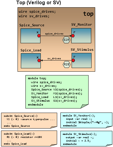
- Side-by-side connection between SPICE and SystemVerilog blocks is allowed to occur in Verilog or SystemVerilog scope, regardless of whether the SystemVerilog block or the SPICE block acts as the driver. See the Side-by-side connection between SPICE and SystemVerilog blocks figure.
Figure 19.6: Side-by-side connection between SPICE and SystemVerilog blocks
Related Topics
- SystemVerilog Binding on SPICE
- Wildcard-Named Port Connections in AMS
- Connecting SystemVerilog Interface to DMS/Verilog-AMS (Electrical) Signals
- Coercion for SystemVerilog Interfaces, Program, or Checker Blocks
- Using Custom ie Parameter and Connect Module Names for UDN-to-Electrical Connections
- Configuring SV-AMS Connect Modules for UDN-UDN, UDN-Logic, and UDN-Real Connections
- Using the SVAMS Parser