Understanding the CPF Format
Introduction
The Common Power Format (CPF) is a strictly Tcl-based format.
The CPF file is a power specification file. This implies that the functionality of the design does not change when sourcing a CPF file. The CPF file complements the HDL description of the design and can be used throughout the design creation, design implementation, and design verification flow.
Objects
The CPF file contains two categories of objects:
Design Objects are objects that already exists in the description of the design.
CPF Objects are objects that are created in the CPF file.
Object Names
Design Objects
The design object name must be a valid SystemVerilog or VHDL name. If a CPF file is written for RTL, use the RTL object names. if a CPF is written for a gate-level netlist, use the gate-level netlist object names.
Note: In VHDL, object names in the format of extended identifier (VHDL LRM,13.3.2) are not supported.
See Object References for more information on referencing design objects.
CPF Objects
CPF objects are created by CPF commands. The string that follows the -name option in a CPF command identifies the CPF object that is created. For example,
create_power_mode -name PM1 ...
This command creates a power mode PM1 in the current scope (part of the design that is visible).
A CPF object can have the same name as a design object, but must have a unique name within the scope.
A CPF object name cannot contain the hierarchy delimiter character.
See Object References for more information on referencing CPF objects inside and outside the current scope.
Object Lists
Lists of objects must be enclosed in braces. CPF files can contain simple and complex lists.
A simple list is a list of single design objects or CPF objects.
Empty Lists
In some cases, the object list specified with a command option can be empty. For example,
create_isolation_rule -name ISO1 -from PD1 -pins [find_design_objects \
-object_type port A*]
If the design has no ports matching the pattern A*, the find_design_objects command retrurns an empty list. In this case, the isolation rule does not apply to any ports in the design. This is equivalent to specifying:
create_isolation_rule -name ISO1 -from PD1 -pins {}
Escape Character
The Tcl escape character is the backslash character (\). Use it to escape special characters that have special meaning to the Tcl interpreter, such as square brackets.
Note: The escape character is not required when the special character is contained within curly braces or double quotes.
Hierarchy Delimiter
The supported hierarchy delimiter characters are
The hierarchical delimiter can be specified using the set_hierarchy_separator command. See Information Inheritance for more information on the scope sensitivity of this command.
This character only has this special meaning in object names. An escaped hierarchy delimiter character loses its meaning as a hierarchy delimiter.
The semantics of building an object reference using the hierarchical separator are specified in Object References.
In the following rule example, the period is the default hierarchy delimiter. The first period is escaped, while the second period is not. Consequently the second period acts as hierarchy delimiter, and instance c[0] is considered to belong to hiearchical instance named block.xxx.
create_state_retention_rule -name ret -instances{block\.xxx.c[0]}
Note: The hierarchy delimiter is also the pin delimiter when referencing a pin object.
Wildcards
You can specify multiple objects of the same type by including wildcards. Wildcards are expanded only on objects within the current scope.
 | Wildcard characters can represent bus delimiters, but they do not represent the hierarchical separator. |
For example, c*[3] can represent c1[3] and c1[0][3], while a*/b can represent a1/b and a2/b, but not a/x/b or a/x/y/b (assuming / is used as the hierarchical separator).
Note: In rule specifications, wildcards are considered to specify the targeted design objects explicitly (by expanding the string to a list). See Different Categories of Rules.
Bus Delimiters
The default bus delimiters are the square brackets ([ ]).
Because the square brackets ([ ]) are reserved characters in Tcl syntax, you can do one of the following for bus bit names:
Enclose the bus bit name in braces
Escape the open square bracket ([) and the closing square bracket (]) when you use these characters as bus delimiters
The square brackets only have this special meaning in object names.
When the entire object name is escaped, the square brackets lose their meaning as bus delimiters. For example, the Verilog names a[0] and \a[0] are not equivalent. Only a[0] represents bit 0 of bus a, while \a[0] is a scalar object name. To avoid Tcl errors for the scalar object name in CPF, enter it as either
The recommended format for a list of objects is: {{a\[0\]} {a\[1\]}}
Range Specification
To specify a range (multiple bits of a bus or of a register array), use the bus delimiters and the colon (:). For example:
a[2:7]
b[6:3]
c_reg[4:2]
To specify all pins of a bus pin or bus port, use the bus pin or bus port name without a range.
Individual Registers Names
For a CPF file written for an RTL design, the register names are based on
Examples of register names in CPF: register_A, register_A[0]
The format of a register name in RTL and the corresponding flip-flop or latch instance names in the netlist can be different. When reading in a CPF file written for RTL together with a gate-level netlist, you need to specify how the base name and bit information are represented in the gate-level netlist. This is explained in the following sections.
Specifying the Representation of the Base Name
 |
To specify the suffix that is appended to the base name of a flip-flop or latch instance in the netlist, use the set_register_naming_style command. |
string%s
See Information Inheritance for more information on the scope sensitivity of this command.
An instance name is always started with the base name.
The suffix is appended to the base name to form the instance name, according to the format specified in the string.
If the corresponding RTL register is an array,
%srepresents the bit information (see also Specifying the Representation of the Bits).
Specifying the Representation of the Bits
| |
To specify how the bit information of a flip-flop or latch instance is represented in the netlist, use the set_array_naming_style command. |
[ character]%d[character]
See Information Inheritance for more information on the scope sensitivity of this command.
For example, this option can have values such as:
<%d>,\[%d\], _%d_, _%d
A suffix is generated for each dimension, according to the format specified in this string.
The %d represents an index of a certain dimension.
All pieces of the suffix are concatenated, from the highest dimension to the lowest dimension, to form a combined suffix for multi-dimensional arrays.
Examples
Assume the following RTL input:
reg a;
reg [3:2] b;
reg [5:4][3:2] c;
If you specify the following commands:
If you specify the following commands:
If you specify the following commands:
| Because the square brackets represent command substitution in the Tcl language, you need to either escape the entire instance name or escape each bracket character and enclose the entire name in braces, if you want to reference these instance names in CPF commands. The following are equivalent: |
{c[4][2]}
and
c\[4\]\[2\]
Expressions
In this document, all expressions refer to SystemVerilog Boolean expressions. The current version only supports the following operators for Boolean expressions:
All operators associate left to right. When operators differ in precedence, the operators with higher precedence apply first. In the table above, the operators are shown in order of precedence.
Unless otherwise specified, operands can be one of the following:
|
Units
To specify the power unit, use the set_power_unit command. The default power unit is mW.
To specify the time unit, use the set_time_unit command. The default time unit is ns.
All voltage values must be specified in volt (V).
Example
Consider the example design shown in Figure 3-1.
Figure 3-1 Example Design for CPF
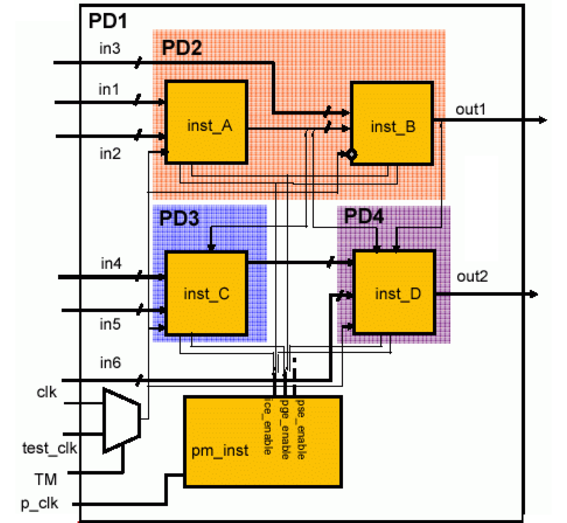
The top-level of the design and hiearchical instance
pm_instbelong to the default domainPD1Hierarchical instances
inst_Aandinst_Bbelong to power domainPD2Hierarchical instance
inst_Bis an instantiation of an IP block. Its power domain is mapped to power domainPD2.The IP is designed to be used either in a switchable or non-switchable top design. If it is used in a switchable top design, all of the registers of
inst_Bneed to be implemented as state retention flops.Hierarchical instance
inst_Cbelongs to power domainPD3Hierarchical instance
inst_Dbelongs to power domainPD4
Table 3-1 shows the static behavior (voltage) for each power domain in each of the modes.
Note: A voltage of 0.0V indicates that the power domain is off.
Table 3-1 Static Behavior
The power manager (pm_inst) generates three sets of control signals to control each power domain. These signals are available on pins pse_enable, ice_enable and pge_enable.
Table 3-2 Signals Controlling the Power Domains
CPF File of IP
# Define IP mod_B, file name IPB.cpf
#-----------------------------------
set_design power_design_B -modules mod_B
create_power_domain -name PDX -default
create_state_retention_rule -name RETB1 -domain PDX
end_design power_design_B
CPF File of Top Design
# Define top design
#------------------
set_designtop
# Set up logic structure for all power domains
#---------------------------------------------
includeIPB.cpf
create_power_domain-name PD1 -default
create_power_domain -name PD2 -instances {inst_A} \
-shutoff_condition {!pm_inst.pse_enable[0]} -base_domains PD1
create_power_domain -name PD3 -instances inst_C \
-shutoff_condition {!pm_inst.pse_enable[1]} -base_domains PD1
create_power_domain -name PD4 -instances inst_D \
-shutoff_condition {!pm_inst.pse_enable[2]} -base_domains PD1
set_instanceinst_B -domain_mapping { PDX PD2 } -design mod_B
# Define static behavior of all power domains and specify timing constraints
#---------------------------------------------------------------------------
set_instanceinst_B -design power_design_B -domain_mapping { PDX PD2 }
create_nominal_condition-name high -voltage 1.2
create_nominal_condition -name medium -voltage 1.1
create_nominal_condition -name low -voltage 1.0
create_power_mode-name PM1 -domain_conditions {PD1@high PD2@medium PD3@high \
PD4@low}
update_power_mode-name PM1 -sdc_files ../SCRIPTS/cm1.sdc \
-activity_file ../SIM/top_1.tcf -activity_file_weight 1
create_power_mode -name PM2 -domain_conditions {PD1@high PD3@high PD4@low}
update_power_mode -name PM2 -sdc_files ../SCRIPTS/cm2.sdc
create_power_mode -name PM3 -domain_conditions {PD1@high PD4@low}
create_power_mode -name PM4 -domain_conditions {PD1@low}
# Set up required isolation and state retention rules for all domains
#--------------------------------------------------------------------
create_state_retention_rule-name sr1 -domain PD2 \
-restore_edge {!pm_inst.pge_enable[0]}
create_state_retention_rule -name sr2 -domain PD3 \
-restore_edge {!pm_inst.pge_enable[1]}
create_state_retention_rule -name sr3 -domain PD4 \
-restore_edge {!pm_inst.pge_enable[2]}
create_isolation_rule-name ir1 -from PD2 \
-isolation_condition {pm_inst.ice_enable[0]} -isolation_output high
create_isolation_rule -name ir2 -from PD3 \
-isolation_condition {pm_inst.ice_enable[1]}
create_isolation_rule -name ir3 -from PD4 \
-isolation_condition {pm_inst.ice_enable[2]}
create_level_shifter_rule-name lsr1 -to {PD1 PD3}
end_design