Power Domains and Modes
-
Base and Derived Power Domains
Primary and Secondary Power Domains of Instances
Secondary Power Domain of Isolation Instances
Secondary Domain of Retention Logic
Secondary Power Domain of Global Cells
Power Domains
Power Domain Categories
CPF considers three categories of power domains as shown in Figure 4-1.
Figure 4-1 Categories of Power Domains
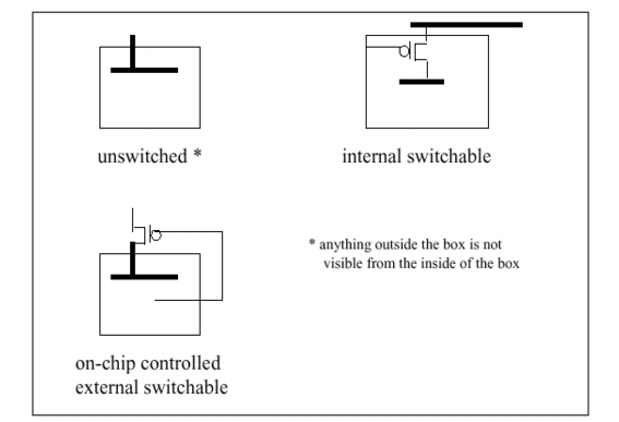
Designers must accurately describe the design intention by correctly specifying the shutoff conditions. Implementers must correctly describe the power and ground network and indicate if there are external shutoff conditions. Verification tools should be able to check if the implementation matches the design intent.
unswitched domain
This domain is never powered down by controls in the scope in which it is created.
Specify the create_power_domain command without the
-shutoff_conditionor the -external_controlled_shutoffoptions.If you need to create its power and ground nets in CPF, create them without any external shutoff conditions.
 | An unswitched power domain can be part of a power mode definition where the domain is associated with a nominal condition of state off, indicating that the domain can be shut off externally. |
create_power_domain -name PD1 -instances {...}
create_power_domain -name PD2 -instances {...}
create_power_mode -name PM1 -domain_conditions {PD1@on PD2@on}
create_power_mode -name PM2 -domain_conditions {PD1@on PD2@off}
internal switchable domain
This domain can be powered down by an on-chip power or ground switch. This domain gets its power supply from another domain through a power switch network.
To model an internal switchable domain
Specify the condition that causes the power domain be powered down through the
-shutoff_conditionoption of the create_power_domain command.Specify the domain from which the switchable domain (or the power switch) gets its power supply through the
-base_domainsoption of thecreate_power_domaincommand.(optional) For physical implementation, define the on-chip power or ground switch using a power switch rule associated with the internal switchable domain (see Chapter 6, "Precedence and Semantics of the Rules," for more information).
For an internal switchable domain, the power switch rules associated with the power domain (specified with the
-enable_condition_xoption of the update_power_switch_rule command) determine how the shutoff behavior for the domain will be implemented. The verification tools should check the consistency between the shutoff condition defined for the power domain and the shutoff condition derived from all associated power switch rules.
on-chip controlled external switchable domain
This domain can be powered down by an external power switch (outside of the chip), but the external switch is controlled by signals on the chip.
To model an on-chip controlled external switchable domain
 |
Specify the condition that causes the power domain be powered down through the -shutoff_condition option together with the -external_controlled_shutoff option of the create_power_domain command. |
Note: Since the power (or ground) switch is not part of the chip, it cannot be described through a power switch rule.
For an on-chip controlled external switchable domain, the implementation of the shutoff behavior for the domain is determined by the external shutoff condition specified for the primary power and ground nets of the power domain (defined in the update_power_domain command). The verification tools should check the consistency between the shutoff condition of the power domain and the external shutoff condition of the primary power and ground nets.
If an external shutoff condition is specified for the primary power and (or) ground net of an on-chip controlled external switchable power domain, it must match the shutoff condition specified for that domain in one of the following ways:
If an external shutoff condition is defined for only the primary power net, it must be identical to the shutoff condition of the domain.
If an external shutoff condition is defined for only the primary ground net, it must be identical to the shutoff condition of the domain.
If an external shutoff condition is defined for both the primary power and ground nets, the domain shutoff condition must be identical to the Boolean OR of the external shutoff condition definition of the power and ground nets.
If power domain Z is specified with shutoff condition !A|!B and with the -external_controlled_shutoff option, power domain Z is considered on-chip controlled external switchable.
If VDD and VSS are the primary power net and primary ground net for the domain, respectively, then the following specifications are valid for this design intent:
VDDis specified with external shutoff condition!A|!B.VSShas no external shutoff condition.VSSis specified with external shutoff condition!A|!B.VDDhas no external shutoff condition.VDDis specified with external shutoff condition!AandVSSis specified with external shutoff condition!BVDDis specified with external shutoff condition!BandVSSis specified with external shutoff condition!A.
Base and Derived Power Domains
A power domain X is a base power domain of power domain Y if the primary power and ground nets of power domain X provide the power supply to domain Y through some power switch network. Domain Y is called the derived domain of domain X.
A derived power domain connects through some sort of device, e.g. a header, footer, or regulator, to one or more base power domains. The shutoff condition for a derived power domain is defined in terms of ports and pins inside this scope (-shutoff_condition) and from which power domain it is derived (-base_domains). A derived power domain is considered to be off whenever all of its base power domains are off.
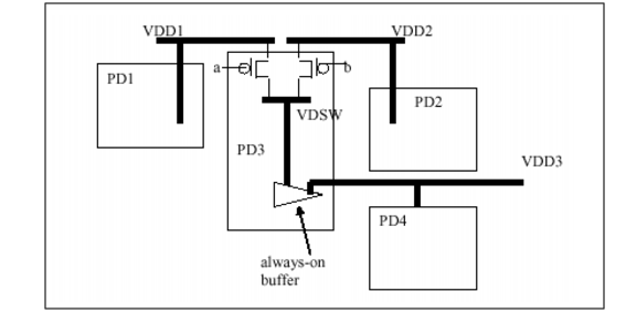
Power domain PD3 in Figure 4-2 has two base power domains, PD1 and PD2.
Figure 4-2 Sample Design
For an internal switchable domain, an error should be given if the base domain definition does not match the power switch rule definition of the domain. For example, the external power net of a power switch rule must be the primary power net of one of the base domains defined in the -base_domains option.
For the example in Figure 4-2, the following CPF is valid:
create_power_domain  -name PD1 ...
create_power_domain  -name PD2 ...
create_power_domain  -name PD3  -shutoff_condition { a & b } \
  -base_domains {PD1 PD2} ...
create_power_domain  -name PD4 ...
update_power_domain  -name PD1  -primary_power_net VDD1
update_power_domain  -name PD2  -primary_power_net VDD2
update_power_domain  -name PD3  -primary_power_net VDSW
create_power_switch_rule -name r1 -domain PD3 -external_power_net VDD1
update_power_switch_rule -name r1 -enable_condition_1 a
create_power_switch_rule -name r2 -domain PD3 -external_power_net VDD2
update_power_switch_rule -name r2 -enable_condition_1 b
In the above example, the external power nets of the switch rules of PD3 are VDD1 and VDD2 which matches the primary power nets defined for the base domains, PD1 and PD2.
It is also possible to have an unswitched domain with a base domains defined. For example, if the two control signals a and b will never be high at the same time, domain PD3 is an unswitched domain and should be created without a shutoff condition. The power switches are just a way to implement dynamic voltage scaling control. In this case, PD3 still has PD1 and PD2 as its base domains by definition.
Primary and Secondary Power Domains of Instances
A power domain X is a secondary power domain of a special low power instance if the primary power and ground nets of the domain X provide the power supply to the secondary power and (or) ground pins of the instance.
A power domain Y is a primary power domain of a standard cell instance if the primary power and ground nets of domain Y provide the power supply to the primary power and ground pins (follow-pins) of the cell.
The secondary power domain definition for special low power logic is handled by corresponding create_xx_rule commands. CPF also provides a special command to give the user the flexibility to specify the expected secondary power domain of any special low power standard cell instances. If the secondary domain is neither specified in the identify_secondary_domain nor create_xx_rule command, the tools will derive the secondary domain as explained in the following sections.
| In this document, the power domain of a special low power cell instance refers to the primary power domain of that instance. |
A derived domain can contain instances that have a secondary power domain definition, such as always-on instances. However the secondary domain of these instances is not always a base domain of the derived domain containing the instances. For the example shown in Figure 4-2, PD4 is not a secondary power domain for PD3 even though PD4 is the secondary domain for the always on buffer instance in PD3.
Secondary Power Domain of Isolation Instances
If you plan to insert isolation logic in the from domain that is being powered down, you may need to use isolation cells with two sets of power supplies. In this case, it is recommended that you specify the secondary power domain for the isolation logic using the -secondary_domain option of the create_isolation_rule command. The primary power and ground nets of the specified secondary domain will be connected to the secondary power and ground pins of the isolation instances.
The secondary domain of an isolation instance is determined in the following order:
The secondary domain specified on the isolation instance using identify_secondary_domain.
The secondary domain specified in the corresponding isolation rule for the isolation instance.
However, the tools cannot determine the secondary domain of the isolation logic in the following cases:
The enable expression is a complex expression of individual signals, possibly driven from different power domains or driven from a port without domain assignment (such as the ports in testbench).
The isolation rule is specified with the
-no_conditionoption
If you plan to use single-rail isolation cells, the isolation rule does not need the specification of the secondary domain. The power domain of the isolation instance depends on the location of that instance. If the rule is specified with the -secondary_domain option, then the single-rail isolation instance must be instantiated in a domain compatible with the specified secondary domain, which implies that the location domain must be on whenever the secondary domain is on.
The verification tools will detect such cases and issue an error.
During simulation, the isolation logic inferred from the isolation rules must only be considered on if and only if the secondary domain is on. If the secondary domain is shut off, the simulators must consider the output of the inferred isolation logic corrupted.
Secondary Domain of Retention Logic
The primary power domain of a state retention instance is the power domain of its parent module. The secondary power domain of a state retention instance is the domain that controls the retention logic within the cell. The primary power and ground nets of the secondary domain will be connected to the secondary power and ground pins of the state retention instances.
The secondary domain of a state retention instance is determined in the following order:
The secondary domain specified on the state retention instance using identify_secondary_domain.
The secondary domain specified in the corresponding state retention rule.
Use the base domain defined for the primary domain of the retention instance if there is one and only one base domain is specified.
If the secondary domain cannot be determined using the above procedure, it is an error.
The operation mode of the retention logic depends on the state of the primary and secondary domain of the retention logic and which of the two drives the output of the retention logic.
During simulation, the retention logic inferred from the retention rules is considered to retain its state if and only if the secondary domain is on. If the secondary domain is shut off, the simulators must consider the output of the inferred retention logic corrupted.
Secondary Power Domain of Global Cells
It is recommended that you use the identify_secondary_domain command to explicitly set the secondary domain of a global cell. When not specified, the secondary domain of the global cell is assumed to be the power domain of the leaf driver of its data input pin.
For simulation purposes, an instance of a global cell keeps its normal function as long as the secondary domain is on. The simulator will corrupt the output of a global cell instance when the secondary domain is powered down.
| Starting from CPF version 2.0, it is recommended to use global cells instead of always-on cells. |
Input and Output Domains of Level Shifters
The definitions of primary and secondary power domains do not always apply to level shifter instances. For level shifters, the more relevant definitions are input domain and output domain, which determine the power/ground connection to the input power/ground pins and output power/ground pins of the cell respectively.
The input power and/or ground pin of the level shifter cell must be connected to the primary power and/or ground net of the input power domain of the level shifter. The output power and/ or ground pin of the level shifter cell must be connected to the primary power and/or ground net of the output power domain. For the case of high to low level shifting, the input power domain specification can be ignored.
For a level shifter cell, all pins related to the input power/ground pins belong to the input domain; all pins related to the output power/ground pins belong to the output domain.
Given a level shifter instance in a design, the input domain of the level shifter instance is determined in the following order:
Input domain specification in the corresponding level shifter rule
Power domain of the leaf driver of this level shifter if the leaf driver is not the output pin of another level shifter cell
Power domain of the parent module of the level shifter instance if the valid location of the cell is from
Given a level shifter instance in a design, the output domain of the level shifter instance is determined in the following order:
Output domain specification in the corresponding level shifter rule
Power domain of the leaf receiver driven by the level shifter instance if the leaf receiver is not the input pin of another level shifter cell
Power domain of the parent module of the level shifter instance if the valid location of the cell is to
Power Domains of Pins and Ports
In most cases, the related power domain of an instance pin is the power domain of the instance.
For more information on how the power domain of an instance is determined, refer to the description of the create_power_domain command.
Some leaf instances (such as multi-rail isolation cells, level-shifter cells, state retention cells) can also have a secondary power domain defined. For more information, refer to Primary and Secondary Power Domains of Instances.
For complex macro cells, the domain assignment of the instance itself is not important. Rather, the related power domain of each of its boundary pins is critical to describe the internal power structure of the cell and drive top-level implementations.
The related power domain of a pin or port object is determined as follows:
If a primary input or primary output port is part of the boundary port definition of a power domain (using the -boundary_port option of create_power_domain), the port belongs to that power domain. Otherwise, it belongs to the default power domain of the design.
A hierarchical pin does not belong to any power domain unless the corresponding port is a defined as a boundary port, and you specified the -honor_boundary_port option in a set_design command in a hierarchical CPF file. In this case the power domain of the hierarchical pin belongs to the power domain of the corresponding port.
Single rail standard cell instance pins belong to the power domain of the instance.
In case of multi-rail standard cell instances, the power domain assignment of the pins depends on the cell definition as well as on the power domain assignment of the instances (refer to Primary and Secondary Power Domains of Instances):
For global cells, state retention cells, and isolation cells:
the pins related to the switchable power and ground pins belong to the primary power domain of the instances
the pins related to the non-switchable power and ground pins belong to the secondary power domain of the instances
For level shifter cells:
the pins related to the input power and ground pins belong to the input domain of the instances
the pins related to the output power and ground pins belong to the output domain of the instances
For more information on the related power and ground pins of the data input and output pins of the special low power cells, such as state retention cell, isolation cell, power switch cell, refer to the description of the
define_xxx_cellcommands in Chapter 9, "define_always_on_cell."
The power domain of a macro cell pin can be directly assigned using the -boundary_ports option of the create_power_domain command.
In the hierarchical flow, you can also define the power domain of a macro cell pin using a CPF macro model (see Modeling a Macro Cell for more information). Once the macro cell is instantiated at the chip level, every non-internal switchable power domain of the macro cell must be mapped into a chip-level power domain. The power domain of the macro cell instance pins follow the corresponding cell pin definition or domain mapping specification
Examples
In the following examples, assume that the corresponding level shifter rule has no -input or -output domain specifications.
In the following example, the level shifter shifts from domain PD1 to PD2, is driven by an isolation cell in domain PD1, but is placed in domain PD3. In addition, the level shifter cell was defined with
-valid_location from. As a result, PD1 and PD3 must have the same supply voltages in all power mode definitions.Input pin IN of the level shifter belongs to PD3, the input domain of the level shifter (because the driver of pin IN--the output pin of isolation cell
ISO--belongs to PD3, the secondary domain of ISO). The output pin OUT belongs to the output domain of the level shifter which is PD2 (see Input and Output Domains of Level Shifters).The following example has a back to back level shifter implementation from PD1 (0.8) to PD2 (1.2). The level shifters are located in domain PD3 (1.0). The first level shifter was defined with
-valid_location to, while the second level shifter was defined with-valid_location from.According to the semantics (Input and Output Domains of Level Shifters), pin IN1 belongs to domain PD1, pins OUT1 and IN2 belong to domain PD3, and pinOUT2 belongs to domain PD2.
Modes
Nominal Conditions
A nominal condition is a typical operating condition under which the design or blocks perform. It is defined by the voltages of all power supplies applied to the power domains using this condition. At a minimum, a nominal condition specifies the power supply voltage, but it can also specify the ground supply voltage and PMOS and NMOS bias voltages. Depending on the technology used, this set of voltages determines whether the state of a power domain is on, off or in standby mode.
To define a nominal condition, use the create_nominal_condition command:
create_nominal_condition
-namestring-voltage {voltage|voltage_list}[-ground_voltage{voltage|voltage_list}]
[-state {on | off | standby}]
[-pmos_bias_voltage {voltage|voltage_list}]
[-nmos_bias_voltage {voltage|voltage_list}]
[-deep_pwell_voltage {voltage|voltage_list}]
[-deep_nwell_voltage {voltage|voltage_list}]
On State
Indicates that all logic in the domain operates at operational speed. To improve performance in the on state, you can apply forward body biasing.
To describe forward body biasing, you must specify -pmos_bias_voltage with a value smaller than the value of -voltage and -nmos_bias_voltage with a value greater than the value of -ground_voltage.
create_nominal_condition -name super_fast -voltage 1.2 -ground_voltage 0.0 \
   	 -state on -pmos_bias_voltage 1.0 -nmos_bias_voltage 0.2
Standby State
Indicates that all logic in the domain retain their logic values as long as the inputs are stable. However, if the inputs are changed, the logical values will be corrupted. The standby state can be achieved by reverse body biasing (see example below) or source biasing.
create_nominal_condition -name sleep2 -voltage 1.0 -state standby \
   	 -pmos_bias_voltage 1.2
Off State
The logic of a power domain in an off state will be corrupted unless the logic is associated with a secondary power domain and the on state of this secondary power domain is used to maintain valid values.
create_nominal_condition -name power_down -voltage 0.0 -state off
Power Modes
A steady state of the design in which some power domains are switched on and some power domains are switched off is called a power mode. In a power mode, each power domain operates at a specific nominal condition.
To define a power mode (or a legal configuration of all power domains in a scope), you need to specify the nominal condition of each power domain in that mode using the create_power_mode command. An unreferenced power domain is considered off.
create_power_mode -name drowsy -domain_conditions {PD1@sleep PD2@normal}
For each scope, an implicit power mode definition exists where all power domains at that scope operate in the off state.
In a hierarchical flow, a power mode can also contain any number of power mode control groups operating at specific power modes. See Power Mode Control Groups for more information.
Generic Modes
A generic mode, also referred to simply as mode, is useful in the early design stage to describe one or more functions of a design. It can be used for early functional verification.
To define a generic mode, use the create_mode command.
A power mode can be considered as a special case of mode. While a power mode requires specification of the states of all the power domains in the current scope, a generic mode does not necessarily associate a specific state with each power domain in the current scope.
For example, if the current scope has 3 domains PD1, PD2, and PD3, and the definition of power mode foo omits the condition for PD3, it implies is that PD3 is shut off in mode foo.
create_power_mode -name foo -domain_conditions { PD1@1v PD2@off }
For a generic mode defined the same way, it simply means that the mode applies whenever PD1 is at 1v nominal condition and PD2 is shut off, irrespective of the state of PD3:
create_mode -name newMode -conditions { PD1@1v PD2@off }
The example below shows how CPF modes can be used to describe the functionality of a low power design.
set_design my_handheld_device
...
create_power_domain -name MAIN -default
create_power_domain -name MULTIMEDIA -instance "audio_mac video_mac"
create_mode -name SLEEP \
   	 -condition "MAIN@LOWVDD & MULTIMEDIA@OFF & (sleep_reg == 1)" \
   	 -probability 0.90
create_mode -name ON -condition "MAIN@NOMVDD" -probability 0.10
create_mode -name MM_ACTIVE \
   	 -condition "@ON & MULTIMEDIA@NOMVDD & (media_active_reg == 1)" \
   	 -probability 0.03
...
end_design
This particular design has two power domains: MAIN, which contains the logic for normal operation, and MULTIMEDIA, which contains two blocks responsible for audio and video. The SLEEP mode describes the state of where MAIN is at lower voltage and MULTIMEDIA is completely off. The register named sleep_reg must be one in order to satisfy this mode. The designers estimate that the design will be in the SLEEP mode 90% of the time.
The ON mode describes the mode where the MAIN domain is operational. The design will be in this mode 10% of the time.
The MM_ACTIVE mode is a subset of ON mode. In order for the design to be in this mode, the requirements for mode ON must be satisfied. In addition, the MULTIMEDIA domain must be at the NOMVDD condition and the media_active_reg must set to one. This mode will be active 3% of the time.
Note: Since there is overlap in modes in the example, the probabilities do not add up to 1.0.
Illegal Domain Configurations
To prevent that an unswitched power domain turns off in relation to other power domains (for example to prevent unisolated internal gates or a high current situation), the assert_illegal_domain_configurations command can be used to explicitly declare a power mode or a configuration of domain conditions as illegal.
At the block-level you define a set of legal configurations of block-level power domains that is crucial for the normal operation of the block. However, domain mapping can cause different configurations of these power domains at the top level which are not legal at the block level.You can use the assert_illegal_domain_configurations command to explicitly declare this configuration of domain conditions as illegal at the block level.
To explicitly declare that a particular configuration of domain conditions and/or power mode control group conditions is illegal at the block level, use the -illegal option of the create_power_mode command.
If a domain configuration is covered by both a legal and an illegal power mode definition (or through the assert_illegal_domain_configurations command), the domain configuration will be considered illegal.
The verification tools should issue a warning message if this happens.
Mode Transitions
A mode transition defines when the design transitions from one power mode to a different power mode. A mode transition can be characterized by specifying
An integer of number or range of clock cycles needed to complete the power mode transition.
The time (latency) needed to complete the power mode transition.
You can also define a start condition and end condition that describe the conditions to trigger and flag the end of the transition.
To define a mode transition, use the create_mode_transition command.