Precedence and Semantics of the Rules
Rules in Presence of Existing Power Logic
Precedence of Rules in the Flat Flow
Precedence of Rules in the Hierarchical Flow
Different Categories of Rules
The CPF language uses the concept of rules to describe the low power intent of the design-- that is, describe the type of low power logic that needs to be added to the design. The CPF language supports the following types of rules:
A CPF rule can be associated with a design object either explicitly or implicitly. There are two categories of CPF rules.
Specific rules explicitly specify the targeted design objects. For example,
Isolation or level shifter rules specify the targeted design objects with the
-pinsoption or-excludeoption, or both options.State retention rules specify the targeted design objects with the
-instancesoption or-excludeoption, or both options.
Note: Wildcards are considered to specify the targeted design objects explicitly (by expanding the string to a list).
Generic rules do not explicitly specify the targeted design objects, but the targeted design objects can be derived from some option specified with the rule. For example,
Isolation or level shifter rules specified with
-fromor-tooptions target domain crossings driven by logic in the domains specified with the-fromoption or driving logic in the power domains specified with the-tooption.State retention rules specified with the
-domainoption target all registers or sequential instances in the specified power domain.
 | For isolation and level shifter rules, the targeted design objects refer to hierarchical pins or domain crossings. For state retention rules, the targeted design objects refer to registers or sequential instances. |
Note: A domain crossing is a connection between one driver and one load in two different power domains.
Note: A power switch rule is always associated with a current design. Therefore each power switch rule can be considered a specific rule.
Rules in Presence of Existing Power Logic
A CPF file is normally written for an RTL description to specify the low power intent. (CPF rules specify where the user wants to add power logic in the design.)
This CPF may be used as a golden specification at a lower abstract level for verification or implementation. However, the HDL description may already contain some low power logic independent of what is specified in the CPF file. A netlist can contain low power logic that is either
independent of what is specified in the CPF file
generated based on what is specified in the CPF file
If the design objects targeted by a CPF rule already have some low power logic, the logic in the HDL description takes precedence and the CPF rule is ignored. In other words, the CPF rules specified with the create_xx_rule commands will not be used to generate new low power logic in the design if the targeted design objects already have the required low power logic associated with them. Tools that check for the consistency between CPF and the netlist should report when the existing logic does not match the requirements from the CPF file.
Identifying Existing Power Logic
The CPF language also provides support to identify existing power logic in the HDL description or in the given netlist.
Identify instances that are instantiations of library cells defined by CPF
define_xxx_cellcommands.Identify non-dedicated or generic isolation logic specified in the
identify_power_logiccommand.
 | Even if you instantiated the isolation logic in the RTL description, you must still define the isolation rules to describe your intention for the isolation logic if you want to use the CPF-based flow. |
Precedence of Rules in the Flat Flow
If several rules of the same type apply to the same design objects (see Different Categories of Rules, for more information on the design objects), the following order of precedence applies (arranged from highest to lowest priority):
If multiple CPF rules with the same priority are applied to the same design objects
Note: It is possible that the rule with the highest priority cannot be implemented. (For example, the required cell is not available.) In this case, the tools will give a warning message.
Note:
For isolation rules and level shifter rules, the -location option does not influence the precedence.
The precedence rules apply independently for each value for the -isolation_target option.
Precedence of Rules in the Hierarchical Flow
In the hierarchical flow, you can have a CPF file for a module at the upper level of the hierarchy and a CPF file for a module at a lower level in the hierarchy. In the following, the upper-level module is referred to as the top-level design and the lower-level hierarchy is referred to as the block-level design.
The following policies are followed by all tools when a block-level CPF is integrated into the top-level CPF using the set_instance command:
Block-level rules always overwrite the top-level rules if both rules apply to the same objects at the block-level after domain mapping.
Top-level rules are only applied to block-level objects if the block-level objects have no rule specified and the block is not a macro model.
Block-level state retention, isolation, and level shifter rules do not apply to objects outside the scope of the block. Block-level rules are promoted to the top level, but they only apply to objects in the block.
Note: For more information on how multiple rules on the same signal or net are handled, refer to Multiple Level Shifter and Isolation Rules.
Rules Semantics
Note: In this context, net refers to logical net segment.
Level Shifter Rules
A level shifter rule specifies one or more domain crossings which require level-shifter logic. Level-shifter logic can be required because the leaf drivers and leaf loads of the net have different supply voltages, or because it is part of the design intent.
Note:
An exception can be made for some special pins for which a user-specified input voltage tolerance is defined (see define_power_switch_cell and set_input_voltage_tolerance commands).
The targeted nets are selected by the options -from, -to, and -pins of the create_level_shifter_rule command.
This section contains the following topics:
Interpretation of Different Options
How to Handle Rule for Nets Connected to Bidirectional Pins
When Can Implementation Tools Ignore A Level Shifter Rule
Interpretation of Different Options
-forcespecifies to apply the rule to the specified pin without any of the filtering based on driver and load analysis.Note: The
-forceoption must be specified with the-pinsoption. The-fromor-tooption will be ignored if they are combined with the-forceoption.-fromspecifies to apply the rule to those nets driven by logic in the specified from domains and are driving logic in other power domains.-tospecifies to apply the rule to those nets that only drive logic in the specified to domains and that are driven by logic from another power domain.
If multiple options are specified (excluding the -force option), the requirements specified with all options must be met.
If you combine
-toand-fromoptions, the rule should apply to those nets that only drive logic in the specified to domains and that are driven by logic in the specified from domains.If you combine
-fromand-pinsoptions, the rule should apply to those nets that drive or connect to the specified pins, and also meet the requirements of the-fromoption.If you combine
-toand-pinsoptions, the rule should apply to those nets that are driven by or connected to the specified pins, and also meet the requirements of the-tooption.If you combine
-from,-toand-pinsoptions, the rule should apply to those nets that
How to Handle Rule for Nets Connected to Bidirectional Pins
A bidirectional pin must be treated as both an input pin and an output pin of the associated instance. The semantics of level shifter rules on nets connected to such special pins will then be handled just like other regular cases.
However, to avoid that the user makes mistakes due to the ambiguity of pin or port direction in the functional model, static verification tools (for example those checking the quality of a CPF specification) should issue an error if a bidirectional pin is referenced in both -from and -to options
Furthermore, the tool will issue a warning if bidirectional pins/ports are referenced in a level shifter rule to make the designer aware that the bidirectional ports may be from a blackbox and their direction will be resolved (and changed) after loading the correct module or cell definition.
When Can Implementation Tools Ignore A Level Shifter Rule
Unless the create_level_shifter_rule command was specified with the -force option, level shifter rules can be ignored in the following cases:
The rule is specified for a floating net.
The rule is specified for an undriven net.
The specified net has its leaf level driver and loads belong to the same power domain.
The rule is specified for a net connecting a top-level port and a pad-pin of a pad instance.
Level Shifter Insertion
You can specify the location for the level shifters in the update_level_shifter_rules command using the -location and the -within_hierarchy options.
The -location option specifies the power domain where to insert the level shifters.
frominserts the level shifters in a hierarchy belonging to the originating power domain. Unless further constrained, the location will be the outermost logic hierarchy of the originating power domain.toinserts the level shifters inside a hierarchy belonging to the destination power domain. Unless further constrained, the location will be the outermost logic hierarchy of the destination power domain.parentinserts the level shifters in the logic hierarchy as follows:
any(can only be used with the-within_hierarchyoption) indicates that the level shifter can be inserted in any power domain to which the specified logic hierarchy belongs.
The location for the inserted level shifters can be further refined using the -within_hierarchy option. Unless otherwise specified, the logic hierarchy determined by -location parent or the logic hierarchy specified in -within_hierarchy must be voltage compatible with either the originating power domain or the destination power domain. Two domains are considered as voltage compatible if the two domains have the same nominal conditions or the same voltages in all modes.
Only level shifter cells with a -valid_location specification that is compatible with the insertion location can be used. If -valid_location is
from--the power domain of the insertion hierarchy must be voltage compatible with the originating power domainto--the power domain of the insertion hierarchy must be voltage compatible with the destination power domaineither--the power domain of the insertion hierarchy must be voltage compatible with either the originating or the destination power domainany--the power domain of the insertion hierarchy may belong to any power domain. This is the special case where the logic hierarchy specified through-location parentor-within_hierarchydoes not have to be voltage compatible with either the originating power domain or the destination power domain.
If the update_level_shifter_rules command is specified with the -cells option, the verification tools will check that the specified cells are available in the library sets associated with the domain of the specified instance.
Isolation Rules
An isolation rule specifies one or more domain crossing which require isolation logic. Isolation logic is required when the leaf drivers and leaf loads of a net are in power domains that are not on and off at the same time, or because it is part of the design intent.
The targeted nets are selected by the options -from, -to, and -pins of the create_isolation_rule command.
This section covers the following topics:
Interpretation of Different Options
How to Handle Rule for Nets Connected to Bidirectional Pins
How to Handle Isolation Rules Created Without Isolation Condition
How to Handle Isolation Rules Created With Clamp Value for Isolation Output
When Can Implementation Tools Ignore An Isolation Rule
Interpretation of Different Options
-forcespecifies to apply the rule to the specified pin without any of the filtering based on driver and load analysis.Note: The
-forceoption must be specified with the-pinsoption. The-fromor-tooption will be ignored if they are combined with the-forceoption.-fromspecifies to apply the rule to those nets driven by logic in the specified from domains and are driving logic in other power domains.-tospecifies to apply the rule to those nets that only drive logic in the specified to domains and that are driven by logic from another power domain.
If multiple options are specified (excluding the -force option), the requirements specified with all options must be met.
If you combine
-toand-fromoptions, the rule should apply to those nets that only drive logic in the specified to domains and that are driven by logic in the specified from domains.If you combine
-fromand-pinsoptions, the rule should apply to those nets that drive or connect to the specified pins, and also meet the requirements of the-fromoption.If you combine
-toand-pinsoptions, the rule should apply to those nets that are driven by or connected to the specified pins, and also meet the requirements of the-tooption.If you combine
-from,-toand-pinsoptions, the rule should apply to those nets that
How to Handle Rule for Nets Connected to Bidirectional Pins
A bidirectional pin must be treated as both an input pin and an output pin of the associated instance. The semantics of isolation rules on nets connected to such special pins will then be handled just like other regular cases.
However, to avoid that the user makes mistakes due to the ambiguity of pin or port direction in the functional model, static verification tools (for example those checking the quality of a CPF specification) should issue an error if a bidirectional pin is referenced in both -from and -to options.
Furthermore, the tool will issue a warning if bidirectional pins/ports are referenced in an isolation rule to make the designer aware that the bidirectional ports may be from a blackbox and their direction will be resolved (and changed) after loading the correct module or cell definition.
How to Handle Isolation Rules Created Without Isolation Condition
IP blocks can have special requirements for input ports. For example, when the signals driving these input ports are switched off, the signals must be held at specific values. For these signals, no isolation condition can be specified because the IP developer has no knowledge of how the IP will be used.
For such cases, there is a need to create isolation rules without enable conditions (neither -isolation_condition nor -no_condition option specified). Such isolation rules are called incomplete isolation rules.
On the other hand, a default isolation condition can be specified for a switchable power domain:
create_power_domain [-default_isolation_condition expression]
Note:
An error will be given if a -default_isolation_condition option is specified for an unswitched domain--a domain created without -shutoff_condition or -external_controlled_shutoff option.
In case of an incomplete isolation rule the following restrictions apply:
The target location for the isolation cell must be the from domain if the IP block is a macro cell.
The rule can only be specified for the net that connects to an input port of a module or a macro cell.
To complete an incomplete isolation rule, tools need to check if the power domain containing the leaf level driver of the net selected by the rule has a default isolation condition. If a default isolation condition is defined, this condition can be used by the incomplete isolation rule to make the rule complete. If no default isolation condition was defined for the driving power domain, the incomplete isolation rule is treated as a design constraint.
How to Handle Isolation Rules Created With Clamp Value for Isolation Output
During RTL simulation, special consideration is required for isolation rule specified with clamp_high or clamp_low
The net must be considered corrupted if the signal value is
1(0), and the isolation output is set toclamp_low(clamp_high) when the isolation enable becomes active during power down sequence and before the driving domain is shut off.The clamp value will appear on the net when the driven domain is switched off.
The net must be considered corrupted if the signal value is1(0), and the isolation output is set to
clamp_low(clamp_high) during power up sequence between the time when the power of the driving domain is restored and the time the isolation enable becomes inactive.
When inserting the isolation logic, the implementation tool must
Simply connect the output pin of the cell to the selected net without breaking the net into two net segments (unlike with regular isolation cells with both data input and output pins).
Consider only clamp type isolation cells when the
-cellsoption is specified
When Can Implementation Tools Ignore An Isolation Rule
Unless the create_isolation_rule command was specified with the -force option, isolation rules can be ignored in the following cases:
Isolation logic exists on the selected net and all the following conditions are met:
The isolation cell has the same cell type as requested by the rule
The isolation enable of the cell matches the isolation condition of the rule
The rule is specified for a floating net.
The rule is specified for an undriven net.
The specified net has its leaf level driver and loads in the same power domain.
The isolation condition is specified with virtual ports at the block level but the virtual ports do not have any port mapping at the top level.
The rule is specified for a net connecting a top-level port and a pad-pin of a pad instance.
Note:
If the isolation rule (create_isolation_rule) is specified with the -no_condition option and the rule (update_isolation_rules) is specified with the -cells option and none of the specified cells are specified with the -no_enable option, the implementation tools should issue an error and not insert any isolation logic.
Note:
If the isolation rule is specified with an isolation condition and the rule (update_isolation_rules) is specified with the -cells option and none of the specified cells are specified with the -enable option, the implementation tools should issue an error and not insert any isolation logic.
Isolation insertion
You can specify the location for the isolation logic in the update_isolation_rulescommand using the -location and the -within_hierarchy options.
The -location option specifies the power domain where to insert the isolation logic.
frominserts the isolation logic in a hierarchy belonging to the originating power domain. Unless further constrained, the location will be the outermost logic hierarchy of the originating power domain.toinserts the isolation logic inside a hierarchy belonging to the destination power domain. Unless further constrained, the location will be the outermost logic hierarchy of the destination power domain.parentinserts the isolation logic in the logic hierarchy as follows:
any(can only be used with the-within_hierarchyoption) indicates that the isolation logic can be inserted in any power domain to which the specified logic hierarchy belongs.
The location for the inserted isolation logic can be further refined using the -within_hierarchy option. Only isolation cells compatible with the insertion location may be used. Compatibility is determined by the -valid_location option of the define_isolation_cell command. If -valid_location is
from--this type of cell may only be used forofftoonisolation. Since these cells rely on their primary power and ground pins for their normal function, they must be inserted into a power domain that isonwhenever the source domain ison.to--this type of cell is used forofftoonisolation and relies on its primary power and ground pins for its normal and isolation functions. Therefore, the domain of the insertion hierarchy must beonwhen the destination domain ison.on--this type of cell uses its primary power and ground pins for both the normal and isolation functions. For anontooffisolation, the domain of the insertion hierarchy must beonwhen the originating domain ison.offtoonisolation, the domain of the insertion hierarchy must beonwhenever the destination domain ison.
any--these cells do not rely on their primary power or ground pins for their normal and isolation functions. Thus, there is no restriction on the power domain of the specified hierarchy.
The other two values of -valid_location, to and off, are not commonly used and will be deprecated in a future release. All isolation cells can be described with the above three different valid locations.
if the update_isolation_rules command is specified with the -cells option, the verification tools will check that the specified cells are available in the library sets associated with the domain of the specified instance.
Example
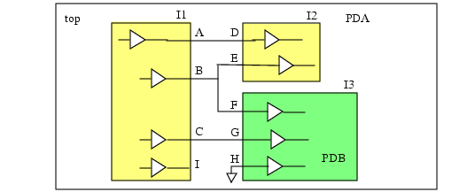
The following example illustrates the effect of the specified options on the selection of the nets. In the design in Figure 6-1, instances I1 and I2 belongs to power domain PDA, and instance I3 belongs to power domain PDB.
Figure 6-1 Effect of the Specified Options on the Nets Selected
The following table shows how the nets are selected based on the specified options:
|
|
|
|
|
The isolation rules can be ignored in the following cases:
Rule
iso1can be ignored for the net connected to pin I in Figure 6-1 because it is a floating net.Rule
iso2can be ignored for the net connected to pinHin Figure 6-1 because it is driven by a tie-low signal.Net segments
ADandBEin Figure 6-1 should not be considered for any rule because the leaf-level driver and loads are in the same power domain.
Multiple Level Shifter and Isolation Rules
How Do Multiple Rules Apply to a Physical Net
Multiple rules can be specified for a physical net.
In this case, the following policy should be used.

Note: The verification tools should issue a warning if multiple rules are specified for the logical net segments of a physical net.
Note:
If multiple isolation rules are specified for the logical net segments of a physical net and all rules use the same value for the -isolation_target option, then all isolation enable signals must be identical or must have been declared as equivalent control pins using the set_equivalent_control_pins command. Otherwise the verification tools should issue an error.
If a physical net has a valid level-shifter rule and a valid isolation rule, and the expected location of the cell for both rules is the same, the implementation tool will first try to find a matching cell (that can be used as both isolation cell and level shifter) to implement both rules. If no such cell can be found, the tool will need to implement the level shifter logic and isolation logic separately according to the rules.
Examples of Multiple Rules on a Physical Net
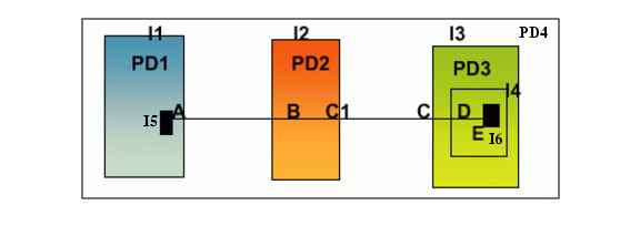
In the design in Figure 6-2, instances I1, I2, I3 belong to power domains PD1, PD2, PD3, respectively. The design has a physical net whose leaf driver (driving instance) is part of power domain PD1 while the leaf load (driven instance) is part of power domain PD3. The logical net segment in PD2 is a wire feedthrough.
Figure 6-2 Multiple Rules on a Physical Net
Example 6-1
Assume the following level shifter rules from the top-level design:
create_level_shifter_rule -name lsPD1 -from PD1
create_level_shifter_rule -name lsPD2 -pins I2/C* -from PD1
create_level_shifter_rule -name lsPD3 -to PD3
In this case, rule lsPD1 applies to the net connected to pin I1/A. Rule lsPD2 applies to the net connected to pin I2/C1. Rule lsPD3 applies to the net connected to pin I3/I4/I6/E.
All these pins are on the same physical net between pinsI1/A and I3/I4/I6/E. Because pin E is the leaf load pin of the physical net and the logical net connected to this pin has rule lsPD3, this rule will be used for level shifter insertion on this physical net and all other rules will be ignored for this physical net. See How Do Multiple Rules Apply to a Physical Net.
Example 6-2
Assume the following level shifter rules from the top-level design:
create_level_shifter_rule -name lsPD1 -from PD1 -to PD3
create_level_shifter_rule -name lsPD3 -to PD3
In this case, both rule lsPD1 and rule lsPD3 apply to the net connected to pin I3/I4/I6/E.However, rule lsPD1 has a higher priority because it has both the -from and -to options, while rule lsPD3 only has the -to option. Therefore, rule lsPD1 takes precedence. For more information, see Different Categories of Rules.
Example 6-3
Assume the following CPF commands from the top-level design:
create_power_domain -name PD1 -default_isolation_condition iso
create_isolation_rule -name isoPD1 -to PD4 -isolation_condition iso1 \
  -isolation_output low
set_instance I3 -domain_mapping { {PD3 PD4} }
set_design mod3
...
create_isolation_rule -name isoPD3 -isolation_output high  -to PD3
end_design
Block-level isolation rule isoPD3 applies to I4/I6/E and is incomplete. According to How to Handle Isolation Rules Created Without Isolation Condition the tool will use the default isolation condition specified for the power domain of the leaf driver of I3/I4/I6/E. In this case, the leaf level driver is an instance in domain PD1 which has a default isolation condition iso. In addition, rule isoPD3 takes precedence over rule isoPD1 based on the policy in Precedence of Rules in the Hierarchical Flow.
How Do Rules Apply to Nets with Multiple Fanouts
Special handling is required for level shifter and isolation cell insertion when the nets have multiple leaf-level loads and different rules apply for the nets connected to the loads.
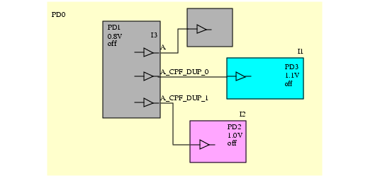
The design in Figure 6-3 has three power domains. The default domain PD1 operates at 0.8v. Power domains PD2 and PD3 operate at 1.0 and 1.1 volt, respectively.
Figure 6-3 Nets with Fanouts in Different Power Domains
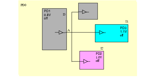
The net connected to pin A fans out to different power domains that each operate at a different supply voltage. If a level shifter rule is applied to the net connected to pin A and the level shifter cell location is in the from domain (see Example 6-3), you need a different level shifter for each load and therefore pin A has to be cloned (see Figure 6-4)
Example 6-4
Assume the following CPF commands from the top-level design:
create_power_domain -name PD0
create_power_domain -name PD1 --instances I3
create_power_domain -name PD2 -instances I2
create_power_domain -name PD3 -instances I1
create_level_shifter_rule -name lvl1 -from PD1
update_level_shifter_rule -names lvl1 -location from
To ensure that the verification tools can correctly verify the netlist with the cloned pins against the original HDL and the golden CPF, the implementation tools need to follow these rules:
Apply the original isolation or level shifter rule to all cloned ports.
Follow the precedence rules in Precedence of Rules in the Flat Flow, Precedence of Rules in the Hierarchical Flow, and How Do Multiple Rules Apply to a Physical Net to resolve any conflicts of rules specified on the physical nets connected to the original port and the cloned ports.
Figure 6-4 Cloned Ports for Nets with Fanouts in Different Power Domains
State Retention Rules
A state retention rule specifies one or more registers (at RTL) or instances in a switchable power domain that need to be mapped to state retention cells.
The targeted registers or instances are selected by the -domain and -instances option of the create_state_retention_rule command.
Interpretation of Different Options
-domainspecifies to apply the rule to all registers or non-state-retention sequential instances in this domain.-instancesspecifies a list of registers or instancesSee the description for the
-instancesoption of the create_state_retention_rule command.
Note:
The user needs to be aware that a state retention rule created with only the -domain option might result in unexpected behaviors during implementation. For example, new sequential instances (such as latches or flops) can be added during DFT synthesis. When the rule is applied to a synthesized netlist, the tools will replace such special sequential instances with retention cells. To avoid this from happening, designers should create a state retention rule with either the -instances or the -exclude option.
How to Model Different Types of State Retention Control
Note: In what follows, power refers to the primary power domain of the state retention logic. The secondary power domain of the state retention logic must be on for the save and restore operation to work properly. When the secondary power domain is off, the state value of the corresponding logic will be corrupted.
To model retention logic with only one retention control, you can use only the -save_edge and-restore_edge options.
If you specify
-save_edge, the register saves the current value when the expression changes totrueand the power is on. The register restores the saved value when the power is turned on.If you specify
-restore_edge, the register saves the current value when the expression changes fromtruetofalseand the power is on. The register restores the saved value when the expression changes fromfalsetotrueand power is on.If you specify both options, the register saves the current value when the save expression changes from
falsetotrueand the power is on. The register restores the saved value when the restore expression changes fromfalsetotrueand the power is on.
To model a retention logic with both save and restore control, specify both the -save_level and -restore_level options. The register saves the current value when the save expression is true and the power is on. The register restores the saved value when the restore expression is true and the power is on.
How to Handle State Retention Rules Created Without Any Control Condition
A state retention rule can be specified without any restore or save conditions. In this case, the rule is incomplete.
To complete an incomplete state retention rule, the tools need to check if the power domain to which the rule applies has a default save or restore condition.
If a default save or restore condition is defined, this condition can be used by the incomplete state retention rule to make the rule complete.
If no default save or restore condition was defined for the power domain, the incomplete state retention rule remains incomplete and will be ignored by the implementation tools.
Handling Master-Slave Type Retention Cells
A master-slave type state retention cell does not have a save or restore control pin. It has a secondary power or ground pin to provide continuous power supply to the slave latch. The clock signal acts as the retention control signal. As a result, users should use the clock signal for the registers as the restore edge and save edge.
If the clock signal is used as the restore or save signal for a flop, then the synthesis tool will synthesize it using a master-slave type retention cell. For library definition, the clock pin needs to be declared as the only save and restore signal and has to be an always-on pin.
Note: This type of cell has some challenges for implementation. For example, in retention mode, the clock needs to be at a specific value to keep the data in the slave latch. All logic on the clock tree must be always-on.
When Can Implementation Tools Ignore A State Retention Rule
State retention rules can be ignored in the following cases:
The rule is incomplete
The rule is specified for an unswitched domain or sequential elements in an unswitched domain.
If the
-requiredoption is specified, the retention logic cannot be optimized.Implementation tools will typically not optimize the retention logic due to hierarchical flow considerations.
There are no matching sequential elements in the domain.
The specified instance is already an instantiation of a state retention cell.
Note: It is an error, if the virtual port used to specify a block-level retention control condition is not mapped to a top-level driver.