General CPF Commands
assert_illegal_domain_configurations
- assert_illegal_domain_configurations -name
mode -
{ -domain_conditions
domain_condition_list- | -group_modes
group_modes_list- | -domain_conditions
domain_condition_list-group_modesgroup_mode_list} - | -group_modes
Asserts that a particular configuration of domain conditions and power mode control group conditions is illegal. The assertion is only checked against conditions explicitly specified. No assumptions are made about unspecified domains.
A verification tool will flag if the design enters a power mode that matches all of the domain and group conditions specified in this command.
An error message is issued if the design operates in a configuration of power domain conditions that have not been defined in a power mode.
Note: Verification tools must issue an error message for illegal power modes, but implementation tools might use these power modes to permit optimization.
Options and Arguments
Example
The following command declares that it is illegal for power domains PD1 and PD2 to have the nominal condition a at the same time.
assert_illegal_domain_configurations -name foo -domain_conditions {PD1@a PD2@a}
Related Information
create_analysis_view
- create_analysis_view
-
-name
string-modemode{ -domain_cornersdomain_corner_list| -group_viewsgroup_view_list| -domain_cornersdomain_corner_list-group_viewsgroup_view_list}- [ -user_attributes
string_list] [-default]
Creates an analysis view. Associates a list of operating corners with a given mode.
The set of active analysis views represents the different design variations (MMMC, that is, multi-mode multi-corner) that will be timed and optimized.
A power design can have no analysis views, but if any are specified, one and only one can be the default. If you do not specify the default, the first view defined will be designated as the default.
Options and Arguments
Example
The following example applies to a design with three power domains (PD1, PD2, and PD3). The design can operate in two modes (M1, M2).
The following table shows the nominal voltages for each power domain in each of the modes.
The best and worst corner voltage of each mode is +10 percent and -10 percent of the nominal voltage for a domain in that mode.
As a result the operating corner and the analysis view can be described as below.
create_operating_corner -name high_max -voltage 1.3 -library_set lib_1.3
create_operating_corner -name low_max -voltage 1.1 -library_set lib_1.1
create_operating_corner -name high_min -voltage 1.1 -library_set lib_1.1
create_operating_corner -name low_min -voltage 1.0 -library_set lib_1.0
create_operating_corner -name off -voltage 0.0 -library_set lib_1.0
create_analysis_view -name fast_M1 -mode M1 \
-domain_corners {PD1@high_max PD2@high_min PD3@low_max}
create_analysis_view -name slow_M1 -mode M1 \
-domain_corners {PD1@high_min PD2@high_min PD3@low_min}
create_analysis_view -name fast_M2 -mode M2 \
-domain_corners {PD1@high_max PD2@low_max PD3@off}
Related Information
create_assertion_control
- create_assertion_control
-
-name
string{ -assertionsassertion_list- | -domains
power_domain_list}- [ -exclude
assertion_list]- [ -shutoff_condition
expression]- [ -type {reset | suspend} ]
Inhibits evaluation of any selected assertion instance when its related power domain is powered down.
By default, assertions remain active when the power domain is powered down.
Note: If the selected assertion instance belongs to an unswitched domain, the evaluation is not affected.
Methodology Implications
An assertion instance is related to a power domain if it is associated with a hierarchical (module) instance that belongs to that power domain. An assertion instance is associated with a hierarchical (module) instance if it is bound to that instance, appears in that instance, or is bound to the module definition for that instance. Each assertion instance is associated with a unique power domain.
An assertion that monitors the behavior of signals that are driven by logic entirely within a single power domain should be contained within, or bound to an instance of, the module containing that logic.
An assertion that monitors the behavior of signals that are driven by logic contained in two or more power domains should be contained within, or bound to an instance of, a module associated with a power domain that is always on when any of the monitored power domains is on.
An assertion that appears in or is bound to a testbench will be considered to be in an unswitched power domain.
 | Tools are not required to check that these methodology guidelines are followed. Designers need to make sure that assertions are created for the right power domain to check the expected behavior. |
Options and Arguments
Examples
In the following examples, a set_hierarchy_separator command has been included in the CPF file to specify that the slash ( / ) is the hierarchy separator.
In the following example, the
create_assertion_controlcommand suppresses the evaluation of two assertion instances associated with hierarchical instanceadd_ef. Instanceadd_efbelongs to power domainPD_add_ef. The assertions are turned off when the power domain shuts off. The-typeresetoption is included to specify that the assertions should be reset. Becauseresetis the default behavior, the-typeoption could be omitted.create_power_domain -name PD_add_ef -instances {add_ef} \
-shutoff_condition {u_pmc/pso_en[2] & u_pmc/cond_3[2]}create_assertion_control -name ac1 \
-assertions {add_ef/SVA_A1 add_ef/SVA_A2} \
-type resetIn the following example, the
create_assertion_controlcommand suppresses the evaluation of all assertion instances associated with all instances included in the power domainsPD_add_abandPD_mux.create_power_domain -name PD_add_ab -instances {add_ab} \
-shutoff_condition {u_pmc/pso_en[0] & u_pmc/cond_3[0]}
create_power_domain -name PD_mux -instances {mux} \
-shutoff_condition {u_pmc/pso_en[3] & u_pmc/cond_3[3]}
...
create_assertion_control -name ac1 -domains {PD_add_ab PD_mux}The following example includes the
-type suspendoption. When power domainPD_add_efis powered down, the specified assertions are turned off. When the power domain is powered up, the assertions are in the same state they were in at power down, and evaluation continues.create_power_domain -name PD_add_ef -instances {add_ef} \
-shutoff_condition {u_pmc/pso_en[2] & u_pmc/cond_3[2]}
...
create_assertion_control -name ac2 \
-assertions {add_ef/SVA_A1 add_ef/SVA_A2} \
-type suspendThe following example specifies the condition when the selected assertions should be disabled.
Related Information
create_bias_net
- create_bias_net
-
-net
net[-driverpin]- [-user_attributes
string_list]- [-peak_ir_drop_limit
float]- [-average_ir_drop_limit
float]
Specifies or creates a bias net to be used as a power supply to either forward or backward body bias a transistor.
Note: Even if this net exists in the RTL or the netlist, it still must be declared through this command if the net is referenced in other CPF commands.
You can use the create_global_connection command to connect the net to the appropriate pins during physical implementation.
Options and Arguments
Example
The following command declares the net
bVddas a bias net driven by pin BVDD.
Related Information
create_global_connection
- create_global_connection
-
-net
net{ -pins pin_list | -ports port_list | -pg_type pg_type_string }- [-domain
power_domain| -instancesinstance_list]
Specifies how to connect a global net to the specified pins. A global net can be a data net, bias net, power net or ground net.
Given a list of pins, if a specified pin is already connected in Verilog, that pin is ignored for connection. For pins that are not connected in Verilog, the following priority determines the pin connection with the specified net:
A connection defined with
-instancehas a higher priority than a connection specified with-domain.If the same pin is specified with multiple connections and all specifications are with
-instance(or all specifications are with-domain), the last definition wins.
This command allows to specify which pins must be connected. You can
Specify all pins to be connected with the
-pinsoptionIf you omit the
-domainor-instancesoption, the global connection applies to the specified pins of the entire design.Combine options to filter the set of pins:
Options and Arguments
Examples
The following command defines the global net connection for net
vdd1. All pins with nameVDDin the design will be connected.The following command defines the global net connection for net
vdd2in power domain PD2. All pins with nameVDDin power domainPD2will be connected.The following command defines the global net connection for net
vddcto pinVDDC ofinstancesrpg1inside hierarchical instanceA.The following command defines the global net connection for net
vddcto pinVDDC ofall leaf instances in hierarchical instancea.b.cstarting withi,and of all leaf instances in hierarchical instancesa.b.c.*starting withi.
Related Information
create_ground_nets
- create_ground_nets
-
-nets
net_list[-voltage {float|voltage_range}]- [-external_shutoff_condition
expression| -internal]- [-user_attributes
string_list]- [-peak_ir_drop_limit
float]- [-average_ir_drop_limit
float]
Specifies or creates a list of ground nets.
Note: Even if this net exists in the RTL or the netlist, it still must be declared through this command if the net is referenced in other CPF commands.
The ground nets are created within the current scope.
Options and Arguments
Example
create_isolation_rule
- create_isolation_rule
-
-name
string[-isolation_conditionexpression| -no_condition]- { -force -pins
pin_list- | -from
power_domain_list| -topower_domain_list|-frompower_domain_listpower_domain_list}-pins- [
pin_list]- [-exclude
pin_list][-isolation_target{from|to}]- [-isolation_output { low | high | hold | tristate |clamp_high | clamp_low}
- [-isolation_control
list_of_additional_controls]- [-secondary_domain
power_domain]
Defines a rule for adding isolation cells.
This command allows to indicate which domain crossings must be isolated. You can
Select all domain crossings driven by logic in the domains specified with the
-fromoption and that are driving logic in other power domainsSelect all domain crossings driving logic in the domains specified with the
-tooption and that are driven by logic from another power domain.Combine options to filter the set of domain crossings:
If you combine
-toand-fromoptions, the rule should apply to those domain crossings that only drive logic in the specified to domains and that are driven by logic in the specified from domains.If you combine
-fromand-pinsoptions, the rule should apply to those domain crossings that drive or connect to the specified pins, and also meet the requirements of the-fromoption.If you combine
-toand-pinsoptions, the rule should apply to those domain crossings that are driven by or connected to the specified pins, and also meet the requirements of the-tooption.If you combine
-from,-toand-pinsoptions, the rule should apply to those domain crossings thatAre driven by or connected to the specified pins
Only drive logic in the specified to domains
Are driven by logic in the specified from domains
If you combine the
-pinsopttion with the-forceoption and with the-from,-to,or -fromand-tooption, the rule applies to all specified pins and the -fromand-tooptions will be ignored.
| If you use the -pins option to select the domain crossings to be isolated, you must always combine this option with the -force, -from, -to or -from and -to options. |
Options and Arguments
Specifies that those already selected domain crossings that are connected to, driven by, or driving the specified pins must be excluded from isolation.
You can specify ports and instance pins. If the specified port or pin is not connected to a net segment selected with the |
|||
Specifies that isolation logic shall be inserted, even in situations in which the rule would normally be ignored (see When Can Implementation Tools Ignore An Isolation Rule). Note: If the isolation logic was already inserted, the tool will not insert the isolation logic again.
Note:
You must specify this option together with the |
|||
Specifies that the rule must be applied to those domain crossings driven by logic in the specified (from) domain and with at least one leaf load in another power domain.
The power domain must have been previously defined with the |
|||
Specifies the condition when the selected domain crossings should be isolated. The condition can be a Boolean function of pins and ports.
If neither this option or the |
|||
To complete an incomplete isolation rule, the
If the |
|||
|
Use the following format to specify a control:
|
|||
It is an error if the isolation condition becomes
It is an error to specify both
To implement a rule with a |
|||
|
|||
Controls the output value at the output of the isolation gates when the isolation condition is
The output can be
A
Rules defined with the
Note:
The |
|||
Specifies when this rule applies.
Note: If two isolation rules apply to the same domain crossing and differ in isolation target, two isolation cells can be inserted.
|
|||
Specifies the name of the isolation rule. Note: The specified string cannot contain wildcards nor the hierarchy delimiter character. |
|||
Specifies that the isolation logic is automatically enabled when the power domains containing the drivers of the selected domain crossings are shut off.
Note:
To implement this type of rule, only isolation cells defined with the |
|||
Specifies to apply the rule to those domain crossings that are connected to, driven by, or driving the specified pins. |
|||
Specifies the domain that provides the power supply for the isolation logic inferred by this rule. If the isolation logic is implemented with an isolation cell with secondary power or ground pins, this domain determines the supplies to which the secondary power and ground pins of the cell must be connected. |
|||
Specifies that the rule must be applied to those domain crossings that are connected to logic belonging to the specified (to) domain and that are driven by a signal from another power domain.
The power domains must have been previously defined with the |
|||
Example
The following command creates isolation rule iso2,that applies to all domain crossings that are driven by or connected to pins whose names start with DA and DB, and that belong to domain domainA. However the rule does not apply if the domain crossings are driven or connected by pins DA_Iso and DB_Iso of domain domainA.
create_isolation_rule -name iso2 -pins { DA* DB* } -exclude { DA_Iso DB_Iso }\
   	 -from domainA
Related Information
create_level_shifter_rule
- create_level_shifter_rule
-
-name
string{ -force -pinspin_list- | -from
power_domain_list| -topower_domain_list|-frompower_domain_listpower_domain_list}-pins- [
pin_list]- [-exclude
pin_list][-bypass_conditionexpression]- [-input_domain
power_domain] [-output_domainpower_domain]
Defines a rule for adding level shifters. A specific rule allows you to indicate on which domain crossings to insert level shifters. You can
Select all domain crossings driven by logic in the domains specified with the
-fromoption and that are driving logic in other power domainsSelect all domain crossings driving logic in the domains specified with the
-tooption and that are driven by logic from another power domain.Combine options to filter the set of domain crossings:
If you combine
-toand-fromoptions, the rule should apply to those domain crossings that only drive logic in the specified to domains and that are driven by logic in the specified from domains.If you combine
-fromand-pinsoptions, the rule should apply to those domain crossings that drive or connect to the specified pins, and also meet the requirements of the-fromoption.If you combine
-toand-pinsoptions, the rule should apply to those domain crossings that are driven by or connected to the specified pins, and also meet the requirements of the-tooption.If you combine
-from,-toand-pinsoptions, the rule should apply to those domain crossings thatAre driven by or connected to the specified pins
Only drive logic in the specified to domains
Are driven by logic in the specified from domains
If you combine the
-pinsopttion with the-forceoption, and with the-from,-to,or -fromand-tooption, the rule applies to all specified pins and the -fromand-tooptions will be ignored.
| If you use the -pins option to select the domain crossings for level shifter insertion, you must always combine this option with the -force, -from, -to or -from and -to options. |
 | The -input_domain and -output_domain options can be used to connect the power and/or ground pin of a level shifter to the non-default power and/or ground net of the power domain in which the level shifter is instantiated. |
Options and Arguments
Specifies the condition when to bypass the voltage shifting functionality.
When the expression evaluates to
Note:
To implement this rule, the tool must insert a bypass level shifter that was specified with the |
|
Specifies that those already selected domain crossings that are connected to, driven by, or driving the specified pins must be excluded from level shifter insertion.
You can specify ports and instance pins. If the specified port or pin is not connected to a net segment selected with the |
|
Specifies that a level shifter must be inserted, even when the rule would normally be ignored (see When Can Implementation Tools Ignore A Level Shifter Rule). Note: If the level shifter logic was already inserted, the tool will not insert the level shifter logic again.
Note:
You must specify this option together with the |
|
Specifies to apply the rule to those domain crossings driven by logic in the specified (from) domain and with at least one leaf load in another power domain.
The power domain must have been previously defined with the |
|
Specifies the input power domain of the level shifter inferred by this rule. By default, the input power domain of a level shifter is the power domain of the logic that drives the net selected by this rule. The input power and/or ground pin of the level shifter cell must be connected to the primary power and/or ground net of the input power domain of the level shifter. Note: For the case of high to low level shifting, the level shifter cell may have no dedicated input power and ground pins. In this case, the input power domain specification will be ignored. |
|
Specifies the name of the level shifter rule. Note: The specified string cannot contain wildcards nor the hierarchy delimiter character. |
|
Specifies the output power domain of the level shifter inferred by this rule. By default, the output power domain of a level shifter is the power domain of the logic driven by the level shifter. The output power and/or ground pin of the level shifter cell must be connected to the primary power and/or ground net of the output power domain of the level shifter. Note: This option is required when an inferred level shifter drives logic that belongs to multiple power domains with different supplies. |
|
Specifies to apply the rule to those domain crossings that are connected to, driven by, or driving the specified pins. |
|
Specifies to apply the rule to those domain crossings that are connected to logic belonging to the specified (to) domain and that are driven by a signal from another power domain.
The power domain must have been previously defined with the |
|
Example
The following command creates level shifter rule lsr1,that applies to all domain crossings that are driven by or connected to pins whose names start with DA and DB, and that belong to domain PD1 or PD2. However the rule does not apply if the domain crossings are driven or connected by pin DA_C of domain PD1 or PD2.
create_level_shifter_rule -name lsr1 -pins { DA* DB* } -exclude { DA_C }\
   	 -from PD1 -to PD2
Related Information
create_mode
- create_mode
-
-name
string-conditionexpression- [-probability
float] [-illegal] - [-probability
Defines a mode of the design. Modes can be non-mutually exclusive, so multiple modes can be active simultaneously at a point in time. In addition, a mode definition does not require the explicit specification of the states of all power domains. As a result, this is a more general specification than power modes.
Options and Arguments
Example
In the following example, the design is in mode
Related Information
create_mode_transition
- create_mode_transition
-
-name
string-frompower_mode -topower_mode[-assertionsassertion_list]- { -start_condition
expression[-end_conditionexpression]- [ -cycles
integer:]integer-clock_pinclock_pin| -latency [float:]float]- | -illegal }
Describes how the transition between two modes is controlled, and the time it takes for each power domain to complete the transition. The transition can be between either power modes or generic modes.
To determine the starting time of a specific mode transition for a power domain, use the following process:
If the power domain is shut off at the end of a mode transition, the domain starts the transition when the shutoff condition changes to
true.If the nominal condition of the ending state is specified in the
-active_state_conditionsof the power domain, the domain starts the transition to the ending state when the condition for this nominal condition changes totrueIf the power domain is shut off at the beginning of a mode transition, the domain starts the transition when the shutoff condition changes to
false.For all other cases, the domain starts the transition as soon as the expression specified in
-start_conditionbecomestrue.
| Mode transitions that start from the same mode cannot have the same start condition. |
Options and Arguments
Related Information
create_nominal_condition
- create_nominal_condition
-
-name
string-voltage {voltage|voltage_list}voltage|voltage_list}]- [-state {on | off | standby}]
- [-pmos_bias_voltage {
voltage|voltage_list}]- [-nmos_bias_voltage {
voltage|voltage_list}]- [-deep_pwell_voltage {
voltage|voltage_list}]- [-deep_nwell_voltage {
voltage|voltage_list}]
Creates a nominal operating condition with the specified voltage. For each voltage, you can specify a single value, two values, or three values:
If you specify one value, you must specify the nominal voltage. For example,
If you specify two values, specify the minimum and maximum voltages. The nominal voltage is considered to be the average of the minimum and maximum voltages. For example,
If you specify three values, you must specify the voltages in the following order: minimum, nominal, and maximum. For example,
If you specify a voltage list, valid values include the minimum, but not the maximum value:

Note: A power domain is switched off if the voltage of its associated nominal condition is 0.
Options and Arguments
Example
The following example applies to a design with three power domains (PD1, PD2, and PD3). The design can operate in three modes (M1, M2, and M3).
This example shows that you can create an explicit nominal condition for a domain that is switched off.
The following table shows the voltages for each power domain in each of the modes.
create_nominal_condition -name high -voltage 1.2
create_nominal_condition -name low -voltage 1.0
create_nominal_condition -name off -voltage 0
create_power_mode -name M1 -domain_conditions {PD1@high PD2@high PD3@low}
create_power_mode -name M2 -domain_conditions {PD1@high PD2@low PD3@off}
create_power_mode -name M3 -domain_conditions {PD1@low PD2@off PD3@off}
Related Information
create_operating_corner
- create_operating_corner
-
-name corner
- -voltage
float[-ground_voltagefloat]- [-pmos_bias_voltage
float] [-nmos_bias_voltagefloat]- [-process
float]- [-temperature
float]- -library_set
library_set_list[-power_library_setlibrary_set_list] - -voltage
Defines an operating corner and associates it with a library set.
Note: The voltage specified in the corner definition associated with a power domain in an analysis view must be consistent with the voltage specified in the nominal condition associated with this domain in the corresponding power mode of the analysis view.
Options and Arguments
Example
The following example uses two library sets to create an operating corner.
define_library_set -name set1 -libraries {a1.lib b1.lib}
define_library_set -name set2 -libraries {a2.lib b2.lib}
create_operating_corner -name ... -voltage ... -library_set {set1 set2}
Related Information
create_pad_rule
- create_pad_rule -name
string -
{-of_bond_ports
port_list| -instancesinstance_list}- -mapping {
mapping_list} - -mapping {
Defines how to map pin groups or power domains of pad instances to top-level power domains.
Options and Arguments
Example
The following command defines cell VDDC_STGIN as a pad cell. It defines three pins in the CVDD pin group. The pins in this group are in the definition of pad rule pad1 mapped to the PD_CORE top domain. The remaining pins of the pad cell belong to the DEFAULT group.
define_pad_cells -cells VDDC_STGIN \
-pad_pins pad -pin_groups {CVDD:{ VDDCORE VDDC2CORE pad} }
...
create_pad_rule -name pad1 -of_bond_ports VDDC \
-mapping { {CVDDPD_CORE} {DEFAULTPD_PAD} }
Related Information
Modeling a Pad Cell in the Common Power Format User Guide
create_power_domain
- create_power_domain
-
-name
power_domain[-instancesinstance_list] [-exclude_instancesinstance_list]- [-boundary_ports
pin_list[-exclude_portspin_list]] [-default]- [-shutoff_condition
expression[-external_controlled_shutoff]]- [-default_isolation_condition
expression]- [
-default_restore_edgeexpr| -default_save_edgeexpr- |
-default_restore_edgeexpr-default_save_edgeexpr- |
-default_restore_levelexpr-default_save_levelexpr]- [-power_up_states {random|high|low|inverted} ]
- [-power_down_states {low|high|random|inverted}]
- [-active_state_conditions
active_state_condition_list]- [-base_domains
domain_list] [-power_source]
Creates a power domain and specifies the instances and boundary ports and pins that belong to this power domain.
A pure virtual power domain is a power domain that is not specified as the default power domain, and for which no instances or boundary ports are defined.
By default, an instance inherits the power domain setting from its parent hierarchical instance or the design, unless that instance was associated with a specific power domain. In addition, all top-level boundary ports are considered to belong to the default power domain, unless they have been associated with a specific domain.
In CPF, power domains are associated with the design objects based on the order of the logical hierarchy. The order in which you create the power domains is irrelevant.
You must define at least one power domain for a design, and one (and only one) power domain must be specified as the default power domain. However, for macro models, power domains must only be specified if the macro models contain any logic. If the macro model consist of only power and ground nets, floating ports, and set_wire_feedthrough nets, a domain is not required.
The top design, identified by the first set_design command, belongs to the default power domain.
| Power domains are scope-specific. If you change the scope to a hierarchical instance (using the set_instance command), a power domain definition can only apply to that hierarchical instance or to the instances (children) of that hierarchical instance. This rule also applies to the default power domain defined in this scope. |
Options and Arguments
Specifies the Boolean condition for each nominal condition or state at which the power domain is considered on or in standby state. When a condition changes to true, the power domain starts the transition to the state specified by the nominal condition. Use the following format to specify an active state condition:
The The expression is a regular CPF expression. The expression must be enclosed in braces. List all nominal conditions that appear with the specified domain in a domain condition for any of the defined power modes. Note: None of the conditions can overlap and the domain must be either in one of the active states or be shut off. Note: This option is only needed if the power domain can operate on different supply voltages and its operation is controlled by a set of signals. |
|||
Specifies a list of base domains that supply external power and/or ground to the primary domain through some switch network. When all base power domains are switched off, the power domain will be switched off irrespective of the shutoff conditions.
If one of the base domains is on or in standby state and the shutoff condition is |
|||
Specifies the list of data inputs and outputs that are considered part of this domain.
Note: Hierarchical instance pins will be ignored if specified. Note: In case of a macro model, the following applies:
|
|||
Identifies the specified domain as the default power domain. All instances of the design that were not associated with a specific power domain belong to the default power domain. |
|||
Specifies the default isolation condition for isolation rules without isolation condition that apply to net segments with leaf driver in this domain.
The expression is a Boolean function of pins. When the expression changes to |
|||
Specifies the default condition when the states of the sequential elements need to be restored for all state retention rules created for sequential instances in this power domain. If no state retention rules were created for this power domain or a list of sequential elements in this domain, this option is ignored.
The expression ( |
|||
Specifies the default condition when the states of the sequential elements need to be saved for all state retention rules created for sequential instances in this power domain. If no state retention rules were created for this power domain, this option is ignored.
The expression ( |
|||
Specifies to exclude those instances already selected through the
If the specified instance is not selected through the |
|||
Specifies to exclude those pins already selected through the
If the specified pin is not selected through the |
|||
Specifies that the power domain being defined is an external switchable power domain. |
|||
Specifies the names of all instances that belong to the specified power domain.
If this option is specified together with the
Instances referred to in a
Instances referred to in a |
|||
Specifies the name of a power domain. Note: The specified string cannot contain wildcards nor the hierarchy delimiter character. |
|||
|
Specifies the value with which to overwrite the default corrupt semantics at the outputs of instances in a power domain after the domain is switched off.
When this option is ommitted, simulation tools should use the default power down semantics for simulation. |
|||
Indicates that the power domain is a power source domain, that is, it models a supply from an on-chip regulator, such as a Low Dropout (LDO) regulator.
See also Modeling a Voltage Regulator. |
|||
Specifies the state to which the non-state-retention cells in this power domain must be initialized after powering up the power domain.
If the option is ommitted, simulation tools should not initialize the states after powering up. |
|||
Specifies the condition when a power domain is shut off. The condition is a Boolean function of pins and ports. |
|||
Examples
For the following example, assume a design with the following hierarchy:
create_power_domain -name PD1 -instances INST1
create_power_domain -name PD2 -instances INST1.INST2create_power_domain -name PD2 -instances INST1.INST2
create_power_domain -name PD1 -instances INST1
This illustrates that the order in which you specify the target domains is irrelevant. The result is that instance
INST1belongs to power domainPD1and instanceINST2belongs to power domainPD2.The following command associates a list of instances with power domain
PD2.The following command defines the active state conditions for power domain
foo.create_power_domain -name foo -instances {...} -shutoff_condition !pso -active_state_conditions { 1.0v@vdd1_en 1.2v@{!vdd1_en}} The following example illustrates that boundary input ports of a macro model can be associated with multiple domains. Input port M of macro
cellAdrives logic in domainsPD2andPD3. Therefor, port M is listed as boundary port of both domains.set_macro_model CellA create_power_domain -name PD1 -default -boundary_ports { psw[0]}
create_power_domain -name PD2 -boundary_ports {MX2 Y2}
create_power_domain -name PD3 -boundary_ports {MX3} ...
create_power_domain -name PD4 -boundary_ports {N YN} ....update_power_domain -name PD1 ...
update_power_domain -name PD2 ....
....
end_macro_modelAssume the top level has the following instances: B, A1, A2, A1/B, A2/B. In the following command,
-instancesinitially selects top-level instancesA1andA2as members of domainPD1but because of the-excludeoption,A2will not be included as a member forPD1.A1/Bis ignored becauseA1/Bwas not selected through the-instancesoption.The following example declares power domain
PDVOUTas a power source domain.set_macro_model regulator
create_power_domain -name PDVIN
update_power_domain -name PDVIN -primary_power_net HAVDD -primary_ground_net AVSScreate_power_domain -name PDVOUT -default -base_domains {PDVIN} -power_sourceupdate_power_domain -name PDVOUT -pmos_bias_net VBB
...
create_nominal_condition -name LDO_range -voltage 1.1 \
-pmos_bias_voltage {1.1 1.3}
...
create_power_mode -name PM -default -domain_conditions \
{ PDREF@REF PDVIN@HVDD PDVOUT@LDO_range }
...
end_macro_model regulator
Note: The primary supply voltage of the base domain can be different from the primary supply voltage of the power source domain.
Related information
For more information on modeling different power domain categories, refer to Power Domain Categories.
create_power_mode
- create_power_mode
-
-name
string[-default]- {-domain_conditions
domain_condition_list|-group_modesgroup_mode_list|-domain_conditionsdomain_condition_list-group_modesgroup_mode_list}- [-condition
expression] - {-domain_conditions
If your design has more than one power domain, and you want to use the same CPF file for simulation, implementation, and verification purposes, you must define at least one power mode.
If you define any power mode, you must define one (and only one) power mode as the default mode within a scope.
A power mode that has any combination of power supplies that is not covered by a legal power mode is illegal.
| You must ensure that any voltage that is contained in the voltage range of several nominal conditions associated with the same power domain, has the same state value in all these nominal conditions. |
Note: Illegal power modes should be treated as an error by verification tools, but may be used by implementation tools to permit optimization.
Options and Arguments
Examples
The following example applies to a design with three power domains (PD1, PD2, and PD3). The design can operate in two modes (M1, and M2).
create_nominal_condition -name high -voltage 1.2 create_nominal_condition -name low -voltage 1.0 create_power_mode -name M1 -domain_conditions {PD1@high PD2@high PD3@low} create_power_mode -name M2 -domain_conditions {PD1@high PD2@low} Note: Since power domain
PD3is switched off in modeM2, you can omit it from the domain conditions when you define modeM2.The following example shows a design with four power domains that can all be switched independently. To specify all combinations of the power domain states, you would need 16 (24) power modes. However, you only need five (4+1) power modes to model the behavior of the design as shown in the table below:
For example, consider the following combination:
Any
ontoofforofftooncrossing is covered by either modesM2orM3. The crossing between domainsPD1andPD2can be ignored because both domains are switched off in this case.In the following example, the nominal conditions that power domain
PD1is associated with have an overlapping voltage ranges [0.7:0.8). This will cause an error because different state values are defined for these voltages.
Related Information
create_power_nets
- create_power_nets
-
-nets
net_list[-voltage {float|voltage_range}]- [-external_shutoff_condition
expression| -internal]- [-user_attributes
string_list]- [-peak_ir_drop_limit
float]- [-average_ir_drop_limit
float]
Specifies or creates a list of power nets.
Note: Even if this net exists in the RTL or the netlist, it still must be declared through this command if the net is referenced in other CPF commands.
The power nets are created within the current scope.
Options and Arguments
Example
The following command declares power nets
vdd3andvdd4with voltage of0.8.
create_power_switch_rule
- create_power_switch_rule
-
-name
string-domainpower_domain{-external_power_netnet| -external_ground_netnet}
Specifies how a single on-chip power switch must connect the external power or ground nets to the primary power or ground nets of the specified power domain.
You can specify one or more commands for a power domain depending on whether you want to control the power domain by a single switch or multiple switches.
By default, the proper power switch cell will be selected from the cells specified through the define_power_switch_cell command. To use a specific cell, use the update_power_switch_rule command.
By default, the inversion of the expression specified for the shutoff condition of the power domain is used as the driver for the enable pin of the power switch cell. For complicated cells with multiple enable pins, or if you want to use a different signal to drive the enable pins, use the update_power_switch_rule command.
Options and Arguments
Example
In the following example, power domain
Xis made switchable through a single switch.
Related Information
create_state_retention_rule
- create_state_retention_rule
-
-name
string{-domainpower_domain| -instancesinstance_list}- [-exclude
instance_list]- [-required]
- [
-restore_edgeexpr| -save_edgeexpr- |
-restore_edgeexpr-save_edgeexpr- |
-restore_levelexpr-save_levelexpr]- [-restore_precondition
expr] [-save_preconditionexpr]- [-retention_precondition
expr]- [-target_type {flop|latch|both}]
- [-secondary_domain
domain] [-use_secondary_for_output]
Defines the rule for replacing selected registers or all registers in the specified power domain with state retention registers.
Note: To implement this rule, only cells defined with the define_state_retention_cell command can be used.
Options and Arguments
Specifies to apply the rule to all registers or non-state-retention sequential instances in this domain. The rule is ignored if the specified power domain is always on or if the domain has no sequential elements.
The power domain must have been previously defined with the |
|
Specifies to exclude the specified list of instances from the list of selected instances that must be replaced with state retention elements.
If you specify the name of a hierarchical instance, all registers or non-state-retention sequential elements in this instance and its children will be excluded. |
|
Specifies the instances that you want to replace with a state retention register.
If you specify the name of a hierarchical instance, all registers or non-state-retention sequential elements in this instance and its children will be replaced. Note: The specified instances can belong to several power domains. If they belong to different power domains, the same conditions will be applied to all of them. |
|
Specifies the name of the state retention rule. Note: The specified string cannot contain wildcards nor the hierarchy delimiter character. |
|
Indicates that the registers selected by this rule must be implemented using retention flops or latches. If you omit this option, the selected registers may or may not be implemented as retention logic, depending on the top-level rule specification.
When any of the control conditions
It is an error if a register is selected by an incomplete retention rule (see State Retention Rules) with the |
|
Specifies that the states are restored when the expression changes from
The expression (
If you specify this option with the
If this option is omitted but the
If you omitted both the
If this option is specified, the rule must be implemented whether or not the |
|
Specifies that the states are restored when the restore expression is
The expression (
If you specify this option with the
If you omitted both the
If this option is specified, the rule must be implemented whether or not the |
|
Specifies an additional condition that must be met for the restore operation to be successful. The condition can be related to the clock, set and reset signals, but should not include signals that directly control the save and restore function of the cell.
If this option is not specified, the restore operation is performed when the
The operands of the expression ( |
|
Specifies an additional condition that must be met (between the time that the power domain of the retention logic is powered down and powered up) for the retention operation to be successful. The condition can be related to the clock, set and reset signals, but should not include signals that directly control the save and restore function of the cell.
The expression ( If the condition is violated, the retention operation will fail and the simulation tools will corrupt the saved values. |
|
Specifies that the states are saved when the expression changes from
The expression (
If you specify this option with the
If this option is omitted but the
If you omitted both the
If this option is specified, the rule must be implemented whether or not the |
|
Specifies that the states are saved when the save expression is
The expression (
If you specify this option with the
If you omitted both the
If this option is specified, the rule must be implemented whether or not the |
|
Specifies an additional condition that must be met for the save operation to be successful. The condition can be related to the clock, set and reset signals, but should not include signals that directly control the save and restore function of the cell.
If this option is not specified, the save operation is performed when the
The operands of the expression ( |
|
Specifies the name of the power domain that provides the continuous power when the retention logic is in retention mode. During implementation, the primary power and ground nets of this domain must be connected to the non-switchable power and ground pins of the state retention cells. |
|
Specifies the type of sequential elements to convert to state retention registers.
If you specify |
|
Specifies that the output of the retention logic must retain the previous value when the primary domain is shut off and the secondary domain is on. In this case, the output pin of the instance is associated with the secondary domain of the instance. By default, the output of the retention logic is corrupted when the primary domain is shut off and the secondary domain is on. In other words, the output of the instance is associated with the primary domain of the instance. If both the primary and the secondary domain are off, then the output will be corrupted. |
|
Example
In the following example, module IPBlock is instantiated as instance IPInst in design Top. Instance IPInst is part of a switchable power domain X.
IPblock.cpf is the CPF file for IPBlock:
set_design IPBlock
create_state_retention_rule -name sr1 -instances *
end_design
Consider the following 2 CPF files for the design Top:
Related Information
How to Model Different Types of State Retention Control
define_library_set
- define_library_set
-
-name
library_set-librarieslist[-user_attributesstring_list]
Options and Arguments
Example
define_library_set -name PD1_set -libraries {pads_1v.lib {ss_1v.lib ss_1v2.lib} }
Related Information
end_design
- end_design
-
[
power_design_name]
Used with a set_design or update_design command, groups a number of CPF commands defining power intent that will be applied to the top module or to instances of one or more logic modules.
Options and Arguments
Example
Top
   	 Inst_A (mod_A)
   	    	 Inst_B (mod_B)
The names in parentheses are the corresponding module names.
set_design mod_B
# the following commands apply to hierarchy under mod_B
...
end_design mod_B
set_design Top
# the following commands apply to Top
...
# change scope to Inst_A
set_instance Inst_A
set_design mod_A
# the following command apply to hierarchy under mod_A
...
set_instance Inst_B -design mod_B
# the following commands still apply to hierarchy under mod_A
...
# change scope to Top
end_design mod_A
# the following commands apply to Top
...
end_design Top
Related Information
CPF Modeling for Hierarchical Design
end_macro_model
- end_macro_model
-
[
macro_mode_name]
Used with a set_macro_model command, groups a number of CPF commands that define power intent that will be applied to instances of one or more macro cells.
Options and Arguments
Specifies the name of the macro model used with the
Note:
The macro model name must match the name specified in the immediately preceding |
||
Related Information
end_power_mode_control_group
- end_power_mode_control_group
Used with a set_power_mode_control_group command, groups a set of CPF commands that define the power modes and power mode transitions that apply to the group defined by the preceding set_power_mode_control_group command.
Related Information
find_design_objects
- find_design_objects
pattern -
[-pattern_type {name | cell | module}]
- [-scope
hierchical_instance_list]- [-object {inst | port | pin | net}] [-direction {in | out | inout}]
- [-leaf_only | -non_leaf_only ]
- [-hierarchical] [-exact | -regexp] [-ignore_case]
- [-scope
Searches for and returns design objects that match the specified search criteria in the specified scope. This provides a general way to select design objects for use in CPF commands. All objects are returned with respect to the current scope.
Options and Arguments
Examples
Assume the current scope is top with the following hierarchy:
top
   	 a
   	    	 a (inst of cell AND)
find_design_objects a
find_design_objects a -hierarchical
find_design_objects a -hierarchical -leaf_only
find_design_objects a -hierarchical -non_leaf_only
find_design_objects a -object inst -hierarchical R
find_design_objects AND -hierarchical -object inst -pattern_type cell
find_design_objects AND -hierarchical -object inst -pattern_type module
Related Information
get_parameter
- get_parameter
parameter_name
Returns the value of a predefined parameter in the current design.
An error message will be given if the parameter is not defined for the current design.
Options and Arguments
|
The parameter must have been defined with the |
Example
IP block fooMod has two parameter values defined, parameter x with default value 0 and parameter y with default value on. When the module is instantiated as fooInst, the corresponding CPF model is also loaded but the parameter value of x is changed to 1 and the parameter value of y is changed to off.
set_design fooMod -ports ... -parameters{ {x 0} {y on} }
....
if { [ get_parametery] == "off" } {
if { [get_parameter x] == 0} {
create_isolation_rule ... -output_type 0
} else {
create_isolation_rule ... -output_type 1
}
}
end_design
set_design top
...
set_instance fooInst -design fooMod -domain_mapping ... \
-port_mapping ... -parameter_mapping{ { x 1} { y off}}
...
end_design
Related Information
identify_always_on_driver
- identify_always_on_driver
-
-pins
pin_list[-no_propagation]
Specifies a list of pins in the design that must be driven by always-on buffer or inverter instances.
By default, all the inverter or buffer drivers of the transitive fanin cone of the specified pins are considered as always-on driver as well.
Options and Arguments
identify_power_logic
- identify_power_logic
-
-type isolation
- {-instances
instance_list| -modulename} - {-instances
Identifies any generic logic used for isolation that is instantiated in RTL or the gate-level netlist.
You can identify the isolation logic by listing all instances, or if all instances are instantiations of the same module, you can specify the module name.
Note: Any instances of special low power cells (such as level shifter cells, isolation cells, and so on) instantiated in RTL or the gate-level netlist that are defined through any of the library cell-related CPF commands are automatically identified.
Options and Arguments
Specifies the names of all instances of the power logic selected through the |
|
Specifies the name of the RTL module whose instances represent the isolation logic. |
|
Example
Assume the following Verilog module is used in the design for the purpose of isolation:
module iso (in, out, en);
input [7:0] in;
output [7:0] out;
   	 assign out = en ? 1 : in;
endmodule
To identify the isolation logic in the design, use the following command in the CPF file:
identify_power_logic -type isolation -module iso
identify_secondary_domain
- identify_secondary_domain
-
-secondary_domain
domain{-instancesinstance_list| -cellscell_list}- [
power_domain[-from power_domain| -topower_domain]]
Identifies the secondary power domain for the selected instances with multiple power and ground pins. The primary power and ground nets of this secondary power domain are connected to the non-switchable power and ground pins of the identified instances.
By default, the secondary power domain for any instance that has both switchable and non-switchable power and ground pins is the secondary power domain defined for the power domain that the instance belongs to.
If several occurrences of this command apply to the same design object, the -instances option has a higher priority than the -cells option, which in turn has a higher priority than the -domain option.
Note: The targeted instances are instances that already existed in the netlist, that is, before the tools insert new low power logic based on the CPF rules.
Options and Arguments
Related Information
include
- include
file
Includes a CPF file or a Tcl file within a CPF file.
The path name to the file can contain a period (.) to refer to current directory of the CPF file being read and ".." to refer to the parent directory of the current directory of the CPF file being read.
Note:
This command differs from the source command in Tcl syntax where a period (.) always refers to the working directory of the tool reading the top level CPF file and ".." refers to the parent of the working directory of the tool reading the top level CPF file.
Options and Arguments
Examples
Consider the following file structure:
home
| models
   	    	 | impl   	      	 --> impl.cpf
   	    	 | sim   	   -->   	  sim.cpf
| tmp --> top.cpf
   	    	 | IP_block     	 --> IP.cpf
   	    	 | tech   	   -->   	  tech.cpf
To include the contents of the
tech.cpfandIP.cpffiles in the top level CPF file (top.cpf), use the following two commands:The path names of these two CPF files are defined with respect to the location (current directory) of the
top.cpffile.To include the contents of the
sim.cpfandimpl.cpffiles in theIP.cpffile, use the following two commands:
set_analog_ports
- set_analog_ports
port_list -
[-user_attributes
string_list]
Identifies a list of top-level analog ports in a power design or a list of analog ports in a macro model.
The specified analog ports must be connected to other ports or pins that were declared as analog ports by the same command or as analog pins in a pad cell.
Analog ports can be associated with a power domain of a macro.
Options and Arguments
Related Information
set_array_naming_style
- set_array_naming_style
-
[
string]
Specifies the format used to name the design objects in the netlist starting from multi-bit arrays in the RTL description. For sequential elements, the bit information is appended to the instance name which is determined by the set_register_naming_style command.
The command returns the new setting or the current setting in case the command was specified without an argument.
Options and Arguments
Specifies the format of the bit information. The string must have the following format: You can use angle brackets, square brackets, or underscores. |
Example
set_array_naming_style <%d>
Related Information
Specifying the Representation of the Bits
set_cpf_version
- set_cpf_version
-
[
value]
Specifies the version of the format.
The command returns the new setting or the current setting in case the command was specified without an argument.
If specified, this command must be the first CPF command in a CPF file.
| You cannot have multiple occurrences of this command with different values set in the same scope. |
Options and Arguments
Specifies the version. Use a string. |
Example
set_design
- set_design
-
power_design[-modulesmodule_list]- [-ports
port_list] [-input_portsport_list]- [-output_ports
port_list] [-inout_portsport_list]- [-honor_boundary_port_domain]
- [-parameters
parameter_value_list]- [-testbench] ...
- [-ports
Begins the definition of a power design, identified by a name that is unique among power designs within the same scope.
The power intent represented by the power design is defined by the CPF commands between this command and a matching end_design command.
A power design can be applied to a top module or to instances of one or more logic modules.
Options and Arguments
Examples
In the following example, module
mod1is an IP block and has a default switchable domain. The output portOis declared as part of a virtual domain that is always on.set_design mod1 -honor_boundary_port_domain
create_power_domain -name PDVirtual -boundary_ports O
create_power_domain -name PDCore -default -shutoff_condition en \
-base_domains PDVirtual
end_design mod1
set_design top
create_power_domain -name PDAO -default
create_power_domain -name PD2 -shutoff_condition en2
set_instance I1 -design mod1 -domain_mapping {{PDVirtual PDAO}}
end_designWhen module
mod1is instantiated at the top, the block-level domainPDVirtualis mapped into the top level domainPDAO. Because blockmod1is specified with the-honor_boundary_port_domainoption, the boundary domain assignment of portOto domainPDAO(due to the domain mapping) should be treated as a design constraint at the top level, even though the hierarchical pin I1/O has a leaf level driverI1/S/Zin domainI1/PDCoreand a leaf level loadI2/D/Ain domainPD2). The implementation tool can insert a buffer for the top netxwithin power domainPDAOto meet the design requirement.IP block
fooModhas two parameter values defined, parameterxwith default value0and parameterywith default valueon. When the module is instantiated asfooInst, the corresponding CPF model is also loaded but the parameter value ofxis changed to1and the parameter value of isychanged tooff.set_design fooMod -ports ... -parameters{ {x 0} {y on} }
....if { [ get_parametery] == "off" } {
if { [get_parameter x] == 0} {
create_isolation_rule ... -output_type 0
} else {
create_isolation_rule ... -output_type 1
}
}
end_designset_design top
...
set_instance fooInst -design fooMod -domain_mapping ... \
-port_mapping ...-parameter_mapping{ { x 1} { y off}}
...
end_designInstance
I1is instantiated from logic modulefoo, but after synthesis and module uniquification, the logic module is renamed tofoo_1. Using the-modulesoption in combination with thefind_design_objectscommand, the following hierarchical CPF is legal:
Related Information
Virtual Port in
set_diode_ports
- set_diode_ports
-
{-positive
pos_port_list-negativeneg_port_list|-positivepos_port_list| -negativeneg_port_list}
Specifies a list of ports of a macro cell that connect to the positive and negative pins of a diode inside a macro cell.
When you specify both the -positive and -negative options, the specified macro model ports are connected through diodes. You can specify a single positive port and multiple negative ports, or multiple positive ports and one negative port. You cannot specify multiple positive and multiple negative ports when both options are used.
When you specify only the -positive option, each port specified is connected to the anode of a power clamp diode and the cathode of the diode is connected to the primary power of the associated domain of the port.
When you specify only the -negative option, each port specified is connected to the cathode of a ground clamp diode and the anode of the diode is connected to the primary ground of the associated domain of the port.
A port can appear in multiple set_diode_ports commands. However, it is an error if the same port appears in both the -negative and -positive options of the same command.
Note: A port can be declared as a member of a power domain and as a diode port. If a port is only declared as a diode port and not associated with a power domain, it is considered to be a floating port.
Options and Arguments
Specifies the names of the ports that connect to the negative inputs or cathode of a diode. |
|
Specifies the names of the ports that connect to the positive inputs or anode of a diode. |
|
Examples
The following macro cell has two diodes.
|
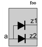
The following commands connect input port
Ato a power and ground clamp diode:The following command causes an error because input port A is specified in the
-positiveand-negativeoptions of the same command.
Related Information
set_equivalent_control_pins
- set_equivalent_control_pins
-
-master
pin- -pins
pin_expression_list- { -domain
domain| -rulesrule_list} - -pins
Specifies a list of pins that are equivalent with a master control pin. The master control pin is part of the definition of a shutoff condition, isolation condition or state retention condition. The referred condition can contain only the master control pin in its expression.
The following requirements apply to the pins:
A master control pin cannot appear as an equivalent control pin in another
set_equivalent_control_pinscommand.An equivalent control pin can only be associated with one master control pin.
A common usage of equivalent control pins is to generate time-staged control signals (control signals with different arrival times) to control the rush current when simultaneously turning on multiple devices at once.
Options and Arguments
Examples
In the following example, the actual shutoff condition for domain X for simulation is
!PDN1 | !PDN2 | PDN3.create_power_domain -name X -shutoff_condition !PDN1 \
-active_state_condition { 1.0v@en1 1.1v@!en1 }set_equivalent_control_pins -master PDN1 -pins {PDN2 !PDN3} -domain X
set_equivalent_control_pins -master en1 -pins {!en2 en3} -domain XThe condition for domain X to be at nominal condition 1.0v is
en1 &!en2 & en3.The condition for domain X to be at nominal condition 1.1v is
!en1 & en2 &!en3.In the following example, assume only an AND type isolation cell is available.
create_isolation_rule -name myISO -from PD1 -to PD2 -isolation_output low \
-isolation_condition pcm/A
Without the presence of equivalent pins, the synthesis tool needs to insert an inverter on the isolation enable line because the isolation logic is enabled when the
pcm/Asignal is high, while the required output of the isolation gate islow.When an equivalent pin with opposite polarity is present, the synthesis tool can use this equivalent control pin and as a result no inverter is required on the control line. In the example below, the synthesis tool can use
pcm/Bwhose polarity is the negation ofpcm/Aas the control driver.
Related Information
Chapter 6, "Precedence and Semantics of the Rules"
set_floating_ports
- set_floating_ports
port_list
Specifies a list of ports of a macro cell that are not connected to any logic inside the macro cell.
These ports are excluded from any power domain defined for the macro cell.
Options and Arguments
Specifies the names of the ports that can be floating. |
||
Related Information
set_hierarchy_separator
- set_hierarchy_separator
-
[
character]
Specifies the hierarchy delimiter character used in the CPF file.
The command returns the new setting or the current setting in case the command was specified without an argument.
Options and Arguments
Related Information
set_input_voltage_tolerance
- set_input_voltage_tolerance
-
{ -power
lower[:upper] | -ground [lower:]upper- | -power
lower[:upper] -ground [lower:]upper}- [-domain
power_domain] [-pinspin_list] - | -power
Specifies the input supply voltage tolerance constraint at the selected input pins. If the driver and receiver voltage difference is more than the tolerance voltage, a power (ground) level shifter is required.
Note:
If the command is used In the hierarchical flow without -pins option, the specified voltage tolerance only applies to the selected pins of the scope in which the command is used.
Options and Arguments


Examples
The following command specifies that the driving power voltage can be 0.1 less or 0.3 larger than the voltage at the input pins without the need for a level shifter.
The following command specifies that the driving power voltage can be 0.1 less than the voltage at the input pins without the need for a level shifter, but does not give a requirement for a high to low shifter.
The following command specifies that the driving power voltage can be 0.3 volt higher than the receiver voltage without a level shifter, but there is always a requirement for low to high shifting.
The following command specifies that the driving ground voltage can be 0.3 less or 0.1 larger than the receiving ground voltage without requiring a ground level shifter.
The following command specifies that the driving power voltage can be 0.2 less or 0.4 larger than the receiving voltage without requiring a power level shifter, and that the driving ground voltage can be 0.3 less or 0.1 larger than the receiving ground voltage without requiring a ground level shifter.
Related Information
set_instance
- set_instance
-
[
instance[-designpower_design| -modelmacro_model]- [-port_mapping
port_mapping_list]- [-domain_mapping
domain_mapping_list]- [-parameter_mapping
parameter_mapping_list] ]
Changes the scope to the specified instance or links a previously defined CPF power design or macro model to the specified instance.
The command returns the current scope in case the command was specified without an argument. If the current scope is the top design, the hierarchy separator is returned.
If the command is specified with an instance name only, it will change the design scope for the purpose of searching design objects referenced in the commands after it.
If the command is specified with an instance name, and without the -design or -model options, but with some other options, it must be followed by a set_design command or a set_macro_model command. Some commands are allowed between set_instance and set_design or set_macro_model. These commands are shown in the Command Dependency table before the set_design command.
The scope is used for naming resolution and affects
All CPF objects referred to in the library cell-related CPF commands are scope insensitive.
| Any rule created in the block-level CPF file that references a virtual port that is declared using the -inout_ports, -input_ports, -output_ports or -ports option of the set_design command, but whose mapping is not specified through the -port_mapping option, will be ignored. |
Options and Arguments
Examples
The following examples assume that
inst1_fooandinst2_fooare instances of the same logic modulefoounder top level moduletop.If both instances use the same power design:
set_design foo
...
end_design foo
set_design top set_instance inst1_foo -design foo set_instance inst2_foo -design foo end_design top If each instances uses its own power design:
set_design foo1
...
end_design foo1
set_design foo2
...
end_design foo2set_design top set_instance inst1_foo -design foo1 set_instance inst2_foo -design foo2 end_design top In the following example,
set_instance inst1_foochanges the scope toinst1_foo. As a result,the power designfoois only defined for scopeinst1_foo. As a result, it is an error to referencefooin the secondset_instancecommand since the scope at this point is at the top level.
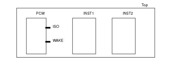
The following example illustrates the use of the
-port_mappingoption.INST1, core logic instantiated from modulemod1, is part of a switchable power domain, and will use state retention logicINST2, core logic instantiated from modulemod1,is part of a switchable power domain, but will not use state retention logicPCM, the power control block
CPF file for module
mod1is calledmod1.cpf, while CPF file for the design Top is calledTop.cpf.Within
mod1.cpfrules for isolation logic and state retention logic are specified. Because the RTL description of modulemod1does not contain ports for the isolation enable and the state retention restore signal, you need to declare the virtual portsiso_enandrestore.When this CPF file is applied to instance
INST1,you must specify the port mapping for both virtual ports.When this CPF file is applied to instance
INST2, you must only specify the port mapping for the isolation enable portiso_en. In this case the state retention rule in themod1.cpffile will be ignored.#mod1.cpf
set_design mod1 -ports { iso_en restore )
...
create_isolation_rule ... -isolation_condition iso_en
create_state_retention_rule ... -restore_edge restore
...
end_design#Top.cpf
set_design Top
...
set_instance INST1 -port_mapping {{iso_en PCM/ISO} {restore PCM/WAKE}}
include mod1.cpf
...
set_instance INST2 -port_mapping {{iso_en PCM/ISO}}
include mod1.cpf
...
end_designIP block
fooModhas two parameter values defined, parameterxwith default value0and parameterywith default valueon. When the module is instantiated asfooInst, the corresponding CPF model is loaded but the parameter value ofxis changed to1and the parameter value of isychanged tooff.set_design fooMod -ports ... -parameters{ {x 0} {y on} }
....
if { [get_parametery] == "off" } {
if { [get_parameter x] == 0} {
create_isolation_rule ... -output_type 0
} else {
create_isolation_rule ... -output_type 1
}
}
end_design
set_design top
...
set_instance fooInst -design fooMod -domain_mapping ... \
-port_mapping ...-parameter_mapping{ { x 1} { y off}}
...
end_design
Related Information
CPF Modeling for Hierarchical Design
set_macro_model
- set_macro_model
macro_model_name[-cellscell_list]
Indicates the start of the CPF content of a custom IP.
A simulation tool that has a behavioral simulation model can take the full description of the macro model and perform power-aware simulation. Tools for static verification and implementation can only use the interface definitions because to them, the macro model is a blackbox.
Only following CPF commands are allowed in a macro model definition:
create_isolation_rule
create_mode_transition
create_nominal_condition
create_power_domain
create_power_mode
create_power_switch_rule
create_state_retention_rule
set_analog_ports
set_diode_ports
set_floating_ports
set_input_voltage_tolerance
set_pad_ports
set_power_source_reference_pin
set_sim_control
set_wire_feedthrough_ports
update_power_domain
Commands issued from inside a macro model are not intended to drive the implementation of the macro, but rather they are intended to describe the behavior of the macro model.
Note: A macro model specification should explicitly associate each non power and ground port to a power domain, or declare it as a floating port, a feedthrough port, or a diode port.
| Within a macro model definition, you cannot have another CPF model. |
Options and Arguments
Examples
The following example illustrates the use of the
-cellsoption to create a single macro model that applies to two different RAM cells.set_macro_model generic_ram -cells { ram_single_port ram_dual_port }
...
end_macro_model
set_instance ram1 -model generic_ram ;# ram1 is instantiated from RAM cell
# ram_single_port
set_instance ram2 -model generic_ram ;# ram2 is instantiated from RAM cell
# ram_dual_portThe following commands describe the power intent for macro cell CellA shown below.
set_macro_model CellA
create_power_domain -name PD_VDD1 -boundary_ports {iso[0] psw[0]} -default
create_power_domain -name PD_VDD2 -boundary_ports {iso[1] psw[1] srpg}
create_power_domain -name PD_VDD1_SW -boundary_ports {M X} \
-shutoff_condition { !psw[0] }
create_power_domain -name PD_VDD2_SW -boundary_ports {Y N} \
-shutoff_condition { !psw[1] }
create_power_switch_rule -name switch1 -domain PD_VDD1_SW \
-external_power_net VDD1
create_power_switch_rule -name switch2 -domain PD_VDD2_SW \
-external_power_net VDD2
update_power_domain -name PD_VDD1 -primary_power_net VDD1 \
-primary_ground_net VSS1
update_power_domain -name PD_VDD2 -primary_power_net VDD2 \
-primary_ground_net VSS1
end_macro_model
Assume a RAM cell has 2 power pins and 1 ground pin. Power pin
VDDAdrives the memory array (memin the behavioral model) and can be shut off externally. Power pinVDDdrives the rest of the peripheral logic of the memory. When PDVDDAis on, PDVDDhas to be on.set_macro_model ram_256x8
create_power_domain -name PDVDD -default -boundary_ports { * }
create_power_domain -name PDVDDA -instances mem*
update_power_domain -name PDVDD -primary_power_net VDD -primary_ground_net VSS
update_power_domain -name PDVDDA -primary_power_net VDDA \
-primary_ground_net VSS
create_nominal_condition -name on -voltage 1.0 -state on
create_power_mode -name on -domain_conditions { PDVDD@on PDVDDA@on }
create_power_mode -name sleep -domain_conditions { PDVDD@on PDVDDA@off }
end_macro_model ram_256x8When the RAM cell is instantiated at the chip level, the
PDVDDAdomain can be mapped into a top-level switchable domain as illustrated below:set_design top create_power_domain -name PDtop1 -default
create_power_domain -name PDtop2 -instances ... -shutoff_condition ...create_power_nets -nets "VDD1 VDD2"
create_ground_nets -nets "VSS"update_power_domain -name PDtop1 -primary_power_net VDD1 \
-primary_ground_net VSS
update_power_domain -name PDtop2 -primary_power_net VDD2 \
-primary_ground_net VSSset_instance -model RAMInst ram_256x8 \
-domain_mapping { {PDVDD PDtop1} {PDVDDA PDtop2 } }end_design top According to the domain mapping, the memory array of the RAM cell now belongs to
PDtop2, and the peripheral logic of the RAM cell and all of its boundary ports belong toPDtop1. For simulation, the memory array will be corrupted whenPDtop2is shut off. For implementation, tools can insert level shifter or isolation logic if there is a level shifter rule or isolation rule defined at the top level and there is domain crossing at the boundary pins of the RAM cell. Also, the power netVDD1at the top level should be connected to the power pinVDDof the RAM cell, and the top level power netVDD2should be connected to the power pinVDDAof the RAM cell.
Related Information
set_pad_ports
- set_pad_ports
pin_list
Specifies a list of ports of a macro cell that connect directly to a bonding port at the chip level.
Use this command if the macro cell models a pad cell or the input of the macro cell has internal pad logic.
Options and Arguments
Specifies the names of the ports that connect to bonding ports. |
Related Information
set_power_mode_control_group
- set_power_mode_control_group -name
group -
{ -domains
domain_list- | -groups
group_list| -domainsdomain_list-groupsgroup_list} - | -groups
Groups a list of power domains and other power mode control groups.
This command together with the end_power_mode_control_group command groups a set of CPF commands that define the power modes and power mode transitions that apply to this group only.
Only following CPF commands are allowed in a power mode control group definition:
create_analysis_view
create_mode_transition
create_power_mode
update_power_mode
Note: By default, all power modes and power mode transitions within a lower scope belong to an automatic defined power mode control group named after the scope.
Options and Arguments
Example
The following example defines a group CORE with three power domains.
set_power_mode_control_group  -name CORE  -domains {CPU FPU CACHE}
create_power_mode -name M1 -domain_conditions { CPU@low CACHE@on}
create_power_mode -name M2 -domain_conditions { CPU@high CACHE@on} create_power_mode -name M3 -default -domain_conditions { CPU@high CACHE@on FPU@on}
create_mode_transition -name CT1 -from M1  -to M2 -start_condition ...
create_mode_transition -name CT2 -from M2  -to M3 -start_condition ...
create_mode_transition -name CT3 -from M3  -to M2 -start_condition ...
create_mode_transition -name CT4 -from M3  -to M1 -start_condition ...
end_power_mode_control_group
Related Information
set_power_source_reference_pin
- set_power_source_reference_pin
pin -
-domain
power_domain-voltage_rangemin:max
Specifies an input pin of the macro cell as the voltage reference pin for a power source domain.
Options and Arguments
Example
The following example declares pin AVDD as the voltage reference pin for power source domain PDVOUT.
set_macro_model regulator
create_power_domain -name PDVOUT -default -base_domains {PDVIN} -power_source
...
create_nominal_condition -name LDO_range -voltage 1.1 -pmos_bias_voltage {1.1 1.3}
...
create_power_mode -name PM -default -domain_conditions \
{ PDREF@REF PDVIN@HVDD PDVOUT@LDO_range }
..set_power_source_reference_pin AVDD -domain PDVOUT voltage_range 1.0:1.1...
end_macro_model regulator
Note:
For proper working of the voltage regulator, the voltage values of pin AVDD must be between 1.0 and 1.1 Volt.
Related Information
Modeling a Voltage Regulator in the Common Power Format User Guide
set_power_target
- set_power_target
-
{ -leakage
float| -dynamicfloat- | -leakage
float-dynamicfloat - | -leakage
Specifies the targets for the average leakage and dynamic power of the current design across all the power modes. All power targets must be specified in the units specified by the set_power_unit command.
Options and Arguments
Specifies the view for which the target is set.
The analysis view must have been previously defined with the |
||
Related Information
set_power_unit
- set_power_unit
- [pW|nW|uW|mW|W]
Specifies the unit for all power values in the CPF file.
The command returns the new setting or the current setting in case the command was specified without an argument.
Options and Arguments
Specifies the power unit. You can specify any of these five values. |
Related Information
set_register_naming_style
- set_register_naming_style
-
[
string%s]
Specifies the format used to name flip-flops and latches in the netlist starting from the register names in the RTL description.
The command returns the new setting or the current setting in case the command was specified without an argument.
Options and Arguments
Specifies the suffix to be appended to the base name of a register. The %s represents the bit information. |
Related Information
Specifying the Representation of the Base Name
set_sim_control
- set_sim_control [-targets
target_list[-excludetarget_list]] -
{-action power_up_replay [-controlling_domain
domain]- |-action disable_corruption -type { real | wreal | integer | reg | module | instance}
- |-action {disable_isolation | disable_retention} }
- [-domains
domain_list| -instancesinstance_list]- [-modules
module_list| -lib_cellslib_cell_list] - |-action disable_corruption -type { real | wreal | integer | reg | module | instance}
Specifies the action to be taken on the selected targets during simulation when the power is switched off or restored.
You can specify this command in a block-level CPF. It is equivalent to a command at the top level with the -instances or -domain options to restrict the target selection.
You must specify a list of targets for a specific action with a given type.
You can combine either the -modules or -lib_cells option with the -instances and -domains options to filter the list of targets selected with the -target and -type options.
When you do not specify any of these options, targets are selected only within the current CPF scope.
When you specify only the
-modulesoption, a search is done for all instances of the specified module(s) through the entire hierarchy of the current CPF scope. Targets are only selected from these instances.When you specify only the
-instancesoption, targets are only selected from the specified instances.When you specify only the
-domainsoption, a search is done for all instances, that belong to the specified power domains, through the entire hierarchy of the current CPF scope. Targets are only selected from these instances.When you specify both the
-domainsand-modulesoptions, targets are selected only from the instances that satisfy the search results of both options.When you specify both the
-instancesand-modulesoptions, a search is done for all instances of the specified module(s) within the instances specifies with the-instancesoption.When you specify only the
-lib_cellsoption, a search is done for all instances of the specified cells through the entire hierarchy of the current CPF scope. Targets are only selected from these instances.When you specify both the
-domainsand-lib_cellsoptions, targets are selected only from the instances that satisfy the search results of both options.When you specify both the
-instancesand-lib_cellsoptions, targets are selected only from the instances that satisfy the search results of both options.
You can use the -exclude option to further filter the selected targets.
To control the action of initial blocks when the power is restored from shutoff, use the -action power_up_replay to specify such initial statements.
Note: Initial blocks are non-synthesizable code used in simulation to create proper startup conditions at time zero of the simulation.
Options and Arguments
Examples
The following command selects all initial blocks found in all instances of the current scope whose label starts with
L,but excludes those blocks whose label starts withL1.The following command selects all initial blocks inside the instances that belong to domains
PD1andPD2.The following command selects all virtual isolation logic inferred from the CPF rules inside the specified domains
PD1andPD2.The following command selects all initial blocks with label
L1from all instances of modulesM1andM2starting at the current scope.The following command selects all initial blocks with label
Lin instanceA.B.C.Assume module
foohas an initial statement with labelthisBlockand hierarchyxwith modulefooalso has an initial statement with that same label. Further assume this module is instantiated in the designtopas instancesA/A2andB, and current scope is top.The following examples show the block-level CPF command followed by their equivalent top-level command. The block-level command applies to block
foo.The following commands select all initial blocks with label
initial1.The following commands select all initial blocks with label
initial1in domainX.Assume that block-level domain X cannot be mapped to any top-level domain.The following commands select all initial blocks with label
initial1in the specified instances.
set_switching_activity
- set_switching_activity
-
{-all | -pins
pin_list| -instancesinstance_list[-hierarchical]}- { -probability
float-toggle_ratefloat- | [-clock_pins
pin_list]float}- [-mode
mode] - { -probability
Specifies activity values (toggle rate and probability) for the specified pins.
The toggle rate is the average number of toggle counts per time unit of a net during a given simulation time.
The probability is the probability of a net being high during a given simulation time.
Options and Arguments
set_time_unit
- set_time_unit
- [ns|us|ms]
Specifies the unit for all time values in the CPF file.
The command returns the new setting or the current setting in case the command was specified without an argument.
Options and Arguments
Specifies the time unit. You can specify any of these three values. |
||
Related Information
set_wire_feedthrough_ports
- set_wire_feedthrough_ports
port_list
Specifies a list of input ports and output ports of a macro cell that are internally connected to each other by a physical wire only.
These ports are excluded from any power domain defined for the macro cell.
Options and Arguments
Specifies the ports in the macro that are connected by a wire only. |
Related Information
update_design
- update_design
-
-name
power_design
Appends the power intent specified between this command and a matching end_design to the previously declared power design identified by the power_design_name.
An example use for update_design is an existing CPF file that is clean and validated, but later on requires additional power intent for new logic added as a result of DFT.
The following commands are not allowed between update_design and end_design:
set_designset_instanceset_macro_modelend_designend_macro_modelupdate_designany commands that are only allowed for macro models
Options and Arguments
Related Information
update_isolation_rules
- update_isolation_rules -names
rule_list{ -location {from | to | parent | any} -
| -within_hierarchy
instance| -cellscell_list[-use_model -pin_mappingpin_mapping_list[-domain_mappingdomain_mapping_list] ]| -prefixstring| -suffixstring| -open_source_pins_only}...
Appends the specified isolation rules with implementation information.
Note:
You must specify at least one of the options besides -names, but you can also combine several options.
| This command is only needed if you have special implementation requirements for the specified rules. If this command is not specified, the tools will automatically determine the correct cell and location according to the specifications in the define_isolation_cell command. |
Options and Arguments
Related Information
update_level_shifter_rules
- update_level_shifter_rules
-
-names
rule_list- { -location {from | to | parent | any}
- | -through
power_domain_list- | -within_hierarchy
instance| -cells {cell_list|list_of_cell_lists}- | -prefix
string| -suffixstring}... - { -location {from | to | parent | any}
Appends the specified level shifter rule with implementation information.
Note:
You must specify at least one of the options besides -names, but you can also combine several options.
| This command is only needed if you have special requirements for implementation of the specified rules. If this command is not specified, the tools will automatically determine the correct cell and location according to the specifications in the define_level_shifter_cell command. |
Options and Arguments
Related Information
Modeling Level Shifters in the Common Power Format User Guide
update_nominal_condition
- update_nominal_condition
-
-name
condition-library_setlibrary_set[-power_library_setlibrary_set]
Associates a library set with the specified nominal operating condition.
Options and Arguments
References the library set to be associated with the specified condition.
The library set must have been previously defined with the
Note:
This library set is used for timing analysis and optimization. When the |
|
Specifies the name of the nominal operating condition. Note: The specified string cannot contain wildcards.
The condition must have been previously defined with the |
|
References the power library set to be associated with the specified condition.
The library set must have been previously defined with the
Note:
If this option is not specified, the timing libraries specified with the |
|
Related Information
update_power_domain
- update_power_domain
-
-name
domain[-instancesinstance_list] [-boundary_portsport_list]- { -primary_power_net
net| -primary_ground_netnet- | -equivalent_power_nets
power_net_list- | -equivalent_ground_nets
ground_net_list| -pmos_bias_netnet| -nmos_bias_netnet| -deep_nwell_net net | -deep_pwell_net net- | -user_attributes
string_list| -transition_slope [float:]float|- | -transition_latency
{from_nomlatency_list}| -transition_cycles{from_nomcycle_listclock_pin}} ...
Specifies implementation aspects of the specified power domain.
If a power domain is implemented in multiple disjoint physical regions, each region has its own power and ground nets. Use the -equivalent_power_nets and -equivalent_ground_nets options to declare these power and ground nets equivalent to the primary power and ground nets. In this case, the following applies:
The primary power and ground pins of all instances in a power domain will be connected to the primary, or equivalent power and ground nets of the domain.
A net referenced in an
-equivalent_xx_netsoption cannot be declared equivalent in more than one power domain unless those power domains have been mapped.If domain X is mapped into domain Y, the equivalent nets of domain X become equivalent nets in domain Y.
Note:
You must specify at least one of the options besides -name, but you can also combine several options.
| A domain can be updated multiple times with -transition_latency and -transition_cycles without overwriting the previous command. In this case, all unique transitions (with different starting and ending states or nominal conditions) will be appended to form a complete state transition table for this domain. If any specific transition is specified more than once, the transition time or cycle specified in the last update_power_domain command will be used. |
Options and Arguments
Incrementally updates a power domain's boundary port membership with the specified list. The effect of this option is the same as the You can use this option to assign boundary ports created during implementation to the correct power domain. |
|
Specifies the net to be used for the deep nwell connection.
The net must have been previously defined with the |
|
Specifies the net to be used for the deep pwell connection.
The net must have been previously defined with the |
|
Specifies a set of ground nets that are equivalent to the primary ground net of the power domain. You can use wildcards (*) to specify a list of ground nets. For macro cell power domains, this option specifies the boundary ports for the equivalent ground nets in the macro cell. |
|
Specifies a set of power nets that are equivalent to the primary power net of the power domain. You can use wildcards (*) to specify a list of power nets. For macro cell power domains, this option specifies the boundary ports for the equivalent power nets in the macro cell. |
|
Incrementally updates a power domain's instance membership with the specified list. The effect of this option is the same as the You can use this option for correct power domain assignment of instances created during implementation. For example, top-level buffering during physical implementation can introduce buffers in the top module; however, the power domain assignment of these buffers should be the power domain of the driving or receiving logic, not the power domain of the top module. |
|
Specifies the name of the power domain.
The power domain must have been previously defined with the |
|
Specifies the net to be used to body bias the n-type transistors of all functional gates in this power domain.
You must have declared this net using the |
|
Specifies the net to be used to body bias the p-type transistors of all functional gates in this power domain.
You must have declared this net using the |
|
Specifies the primary ground net for all functional gates in the specified power domain.
You must have declared this net using the For macro cell power domains, this option specifies the boundary port for the primary ground net in the macro cell. |
|
Specifies the primary power net for all functional gates in the specified power domain.
You must have declared this net using the For macro cell power domains, this option specifies the boundary port for the primary power net in the macro cell. |
|
Specifies the nominal condition of the starting power state, followed by a list of transition cycles to complete the transition to the next power state, followed by the clock pin.
Use the following format to specify the
where If two numbers are specified, the first number indicates the minimum number of clock cycles needed to complete the transition, while the second number indicates the maximum number of cycles needed to complete the transition. Note: If you specify only one value, it is considered to be the maximum number of cycles.
|
|
Specifies the nominal condition of the starting power state, followed by a list of transition times to complete a transition to the next power state.
Use the following format to specify the
where If two numbers are specified, the first number indicates the minimum time needed to complete the transition, while the second number indicates the maximum time needed to complete the transition. Note: If you specify only one value, it is considered to be the maximum time.
Specify the time in the units specified by the |
|
Specifies the transition rate(s) for the supply voltage of the domain during any state transition of the domain. Note: Supply refers to the power supply, ground supply, and the body bias supply. If a domain state transition involves a change in multiple supplies, the voltage used to compute the transition time is in the following order: power, ground, body bias. If two numbers are specified, the first number indicates the minimum transition rate, while the second number indicates the maximum transition rate. Note: If you specify only one value, it is considered to be the maximum slope.
The unit for a transition rate is volt per time unit (specified by the |
|
Attaches a list of user-defined attributes to the domain. Specify a list of strings. |
|
Example
A CPF file can contain the following commands:
update_power_domain -name PD1 -primary_power_net VDD1update_power_domain -name PD1 -equivalent_power_netsVDD2update_power_domain -name PD1 -primary_ground_net VSS
...
update_power_domain -name PD2 -primary_power_net VDD3 -primary_ground_net VSSThe following CPF will cause an error because the primary power net
VDD1was added to the list of equivalent power nets, instead of being specified through the-primary_power_netoption.
Related Information
update_power_mode
- update_power_mode
-
-name
mode{ -activity_filefile-activity_file_weightweight| { -sdc_filessdc_file_list| -setup_sdc_filessdc_file_list| -hold_sdc_filessdc_file_list| -setup_sdc_filessdc_file_list-hold_sdc_filessdc_file_list}- | -peak_ir_drop_limit
domain_voltage_list| -average_ir_drop_limitdomain_voltage_list- | -leakage_power_limit
float- | -dynamic_power_limit
float}...
Specifies the constraints for the power mode.
Note:
You must specify at least one of the options besides -name, but you can also combine several options.
Options and Arguments
Specifies the path to the activity file. Supported formats for the activity files are VCD, TCF, and SAIF.
Note:
You must use the correct file extension to identify the format: |
|
Specifies the relative weight of the activities in this file in percentage. Use a positive floating number between 0 and 100. To estimate the total average chip power over all modes, the activity weights are used to adjust the relative weight of each power mode. Note: If the weights specified for the activity files for the different power modes do not add up to 100, an adjusted weight is used. |
|
Specifies the maximum allowed average voltage change on a power net due to resistive effects in volt (V) for the specified power mode. This net must be the primary power net of the power domain to be considered in the specified mode. Use the following format to specify the maximum allowed average voltage change in the domain: |
|
|
If a domain is omitted from this list, the value for the primary power net of this domain will be 0, unless you specified a value using the |
|
The power domains must have been previously defined with the |
|
Specifies the maximum allowed average dynamic power in the specified mode. |
|
Specifies a list of SDC files to be used for the specified mode. Use this option if the SDC files contain only hold constraints. |
|
Specifies the maximum allowed average leakage power in the specified mode. |
|
Specifies the maximum allowed peak voltage change on a power net due to resistive effects in volt (V) for the specified power mode. This net must be the primary power net of the power domain to be considered in the specified mode. Use the following format to specify the maximum allowed peak voltage change in the domain: Use a floating value for the voltage.
If a domain is omitted from this list, the value for the primary power net of this domain will be 0, unless you specified a value using the |
|
The power domains must have been previously defined with the |
|
Specifies a list of SDC files to be used for the specified mode. Use this option if the SDC files contain both setup and hold constraints.
You cannot combine this option with either the |
|
Specifies a list of SDC files to be used for the specified mode. Use this option if the SDC files contain only setup constraints. |
|
Example
update_power_mode -name PM2 -sdc_files ../SCRIPTS/cm1.sdc \
-activity_file top_pm2.tcf -activity_file_weight 25
Related Information
update_power_switch_rule
- update_power_switch_rule
-
-name
string{ -enable_condition_1expression[-enable_condition_2expression]- | -acknowledge_receiver_1
expression[-acknowledge_receiver_2expression]- | -cells
cell_list| -gate_bias_netpower_net| -prefixstringfloat| -average_ir_drop_limitfloat}...
Appends the specified rules for power switch logic with implementation information.
Options and Arguments
|
|
Specifies the active value of the acknowledge receiver pin. Use a unary expression to express the value. The expression is a Boolean function of an input pin a power controller. When all acknowledge receiver pins are active, this signals to the power controller that the power switch network is turned on completely. An acknowledge receiver pin is driven by the corresponding output pin of the last power switch cell in the power switch network used to implement this rule.
The output pin is specified through the |
|
Specifies the maximum allowed average voltage change across a power switch due to resistive effects in volt (V). |
|
Specifies the name of the library cells that can be used as power switch cells.
A power switch cell must have been defined with the |
|
Specifies the condition when the power switch should be enabled. The condition is a Boolean expression of one or more pins.
If only
If both options are specified, the expression of the Note: If the specified power domain has a shutoff condition, the support set of this expression must be a subset of the support set of the shut-off condition. |
|
|
Default: the inversion of the expression specified for the shutoff condition of the power domain is used as the enable signal driver for the enable pin(s) of the power switch cell |
|
|
Note:
If any pin specified in the enable condition expression is also specified with a |
|
|
Specifies the power net connected to the gate bias power pin of the power switch cell.
Note:
This option must only be specified if the specified power switch cell has a |
|
Specifies the maximum allowed peak voltage change across a power switch due to resistive effects in volt (V). |
|
Examples
In the following example, power domain
Xis made switchable through one on-chip switch that is controlled byena. In addition, the external power net is made switchable through one off-chip switch controlled byenb.create_power_nets -net VDD1 -external_shutoff_condition !enb
create_power_domain -name X -shutoff_condition {!(ena & enb)} -instances ...
update_power_domain -name X -primary_power_net VDD
create_power_switch_rule -name ps1 -domain X -external_power_net VDD1
update_power_switch_rule -name ps1 -enable_condition_1 enaIn the following example, power domain
Xis made switchable through two parallel switches.create_power_domain -name X -shutoff_condition {!(ena & enb)} -instances ...
update_power_domain -name X -primary_power_net VDD
create_power_switch_rule -name ps1 -domain X -external_power_net VDD1
update_power_switch_rule -name ps1 -enable_condition_1 ena
create_power_switch_rule -name ps2 -domain X -external_power_net VDD2
update_power_switch_rule -name ps2 -enable_condition_1 enbIn the following example, power domain
Xis not switchable, but the voltage can be changed through two parallel switches.create_power_domain -name X -instances ...
update_power_domain -name X -primary_power_net VDD
create_power_switch_rule -name ps1 -domain X -external_power_net VDD1
update_power_switch_rule -name ps1 -enable_condition_1 ena
create_power_switch_rule -name ps2 -domain X -external_power_net VDD2
update_power_switch_rule -name ps2 -enable_condition_1 enb
Related Information
update_state_retention_rules
- update_state_retention_rules
-
-names
rule_list{ -cell_typestring- | -cells
cell_list[-use_model -pin_mappingpin_mapping_list[-domain_mappingdomain_mapping_list]]- | -set_reset_control} ...
Appends the specified rules for state retention logic with implementation information.
By default, the appropriate state retention cells are chosen from the state retention cells defined with the define_state_retention_cell command.
If the define_state_retention_cell command is specified with the -cell_type option, the cells defined through that command can only be used by a retention rule that references that particular type through the -cell_type option in the update_state_retention_rules command.
If the define_state_retention_cell command is not specified with the -cell_type option, its cells can only be used by a retention rule that does no have the -cell_type option specified in the update_state_retention_rules command.
| This command is only needed if you have special requirements for implementation of the specified rules. If this command is not specified, the tools will automatically determine the correct cell and location according to the specifications in the define_state_retention_cell command. |
Options and Arguments
Specifies a list of library cells that can be used to map the sequential cells. |
|
Specifies the class of library cells that can be used to map the flops.
Note:
The specified class (cell type) must correspond to a cell type specified in a |
|
The class is a user-defined name that allows to group cells into a class of retention cells with the same retention behavior. |
|
If you specify this option with the |
|
Specifies the mapping of the domains in the macro model to the top-level domains.
This option can be used if there is a CPF macro model with the same name as the first cell specified in |
|
Use the following format to specify a domain mapping:
|
|
The specified domain mapping applies to all instances of the specified state retention cell. |
|
If the macro model has multiple power domains defined, this option must be used. |
|
The power domains must have been previously defined with the |
|
Specifies the names of the rules to be updated. The name can contain wildcards.
The rule must have been previously defined with the |
|
Specifies a list of pin mappings for a complicated state retention cell that cannot be modelled using the |
|
Use the following format to specify a pin mapping:
|
|
|
|
Restricts the rule to those instances that are part of the asynchronous-set-reset-synchronizer circuit--a chain of one or more D type flip flops used to asynchronously set or reset other state elements (flip-flops or latches). This option differentiates these state elements from other state elements in this power domain not used to supply set or reset signals. |
|
Indicates that a simulation tool must use the functional model of the first cell specified in
When this option omitted, a simulation tool can apply the default state retention logic based on the |
|