Hierarchical Flow
Handling Domain Attributes after Domain Mapping
Handling Power Modes after Domain Mapping
CPF Modeling for Hierarchical Design
Handling Boundary Port Domain Definition at Top Level
Introduction
Note: In this context, top-level domain refers to the default power domain of the current design top. In other words, top-level domain does not necessarily refer to the default power domain of the chip.
IP Categories
In a hierarchical flow, your design can instantiate IPs. CPF distinguishes the following categories:
A hard non-custom IP is a block that has been synthesized and placed and routed, but small modifications can still be made. It is also referred to as a hard IP.
 |
To model a hard IP use the set_design command. |
A hard custom IP is a block that is mostly implemented by hand. Custom IP users cannot make any changes to the block and may not have the logical and physical view of the block. Examples are third-party memories. A hard custom IP is also referred to as a custom IP or a macro cell.
| |
To model a macro cell, use the set_macro_model command. |
For more information, see Modeling a Macro Cell.
A soft IP is a block that is a design module supplied by a third-party. Users have the full capability to (re-)synthesize and place and route the design. Examples are synthesizable CPU cores, and so on.
A soft IP is technology independent. A hard IP (custom or non-custom) is technology dependent.
| |
To model a soft IP use the set_design command. |
For more information on using an IP in a hierarchical design, refer to CPF Modeling for Hierarchical Design.
Power Domain Mapping Concepts
In a hierarchical design flow, a block can be implemented with a complex power structure. When the block is instantiated at the top level, the power and ground pins of the block must be connected to the power and ground nets of the top-level design. In other cases, designers might want to merge a power domain of a block into another power domain at the top when the block is instantiated at the top.
Power domain mapping is the operation of merging a power domain of a block with another power domain of the top-level design in which the block is instantiated.
Mapping two power domains involves
Connecting the primary power and ground pins or nets of the block-level domain to the primary power and ground net of the domain specified at the top level
Merging the elements of the power domain of the block into the top-level domain
Resolving the precedence of the top-level and block-level rules
Once a block-level power domain is mapped into a top-level power domain, the two power domains are considered identical and all instances of the two domains share the same power characteristics. For example, the standard cell instances of the two power domains will have their primary power and ground pin (follow pins) connected to the same primary power and ground nets.
 | A warning will be given if the default block-leveldomain is mapped into a top-level domain which is different from the domain to which the block instance is assigned at the top level. The block-level domain mapping takes precedence. In the following example, instance myFoo is assigned to top-level domain PD1. After power domain mapping, PDX, the default power domain of the block, is mapped to power domain PD2 which differs from PD1. |
create_power_domain -name PD1-instances { i1myFoo...} -default
create_power_domain -name PD2 ...
create_power_domain -name PD3 ...
set_instance myFoo -domain_mapping { { PDX PD2} {PDY PD3} }
set_design foo
create_power_domain -namePDX -default-boundary_ports ...
create_power_domain -name PDY -boundary_ports ...
end_design foo
create_power_domain -name PD1-instances { i1 ...} -default
create_power_domain -name PD2 ...
create_power_domain -name PD3 ...
set_instance myFoo -domain_mapping { { PDX PD2} {PDY PD3} }
set_design foo
create_power_domain -namePDX -default-boundary_ports ...
create_power_domain -name PDY -boundary_ports ...
end_design foo
Related commands
set_design and end_design
set_macro_model and end_macro_model
Handling Power Domain Mapping
If the top-level domain is an unswitched domain, all rules defined for the block-level domain need to be reevaluated for their necessity. For example, any state retention rule without -required option created for the block-level domain should be ignored by tools when the block is integrated into the top-level design. See Chapter 6, "Precedence and Semantics of the Rules" for more information.
On the other hand, if the top-level domain is a switchable domain, the verification tools should check the following requirements to ensure the correct usage of domain mapping:
When both the top-level and block-level domains are specified with a shutoff condition, the shutoff conditions must be structurally equivalent.
Each pin in the first expression is electrically connected to a pin or its equivalent control pin in the second expression.
See also set_equivalent_control_pins.
The two expressions become identical if each pin in the first expression is replaced with its corresponding pin in the second expression.
If the block-level domain is an on-chip controlled external switchable domain with base domains, the number of base domains for the block-level domain must correspond to the number of base domains for the top-level domain. In addition, each base domain of the block-level domain must map to a unique base domain of the top-level domain.
An unswitched block-level domain can be mapped into any unswitched top-level domain. However, mapping an unswitched block-level domain into a switchable top-level domain may cause functional failure depending on the actual design of the block. As a result, the verification tools should issue warnings when this occurs. In this case, the block-level domain either inherits the top-level rules completely or just the control conditions. See Chapter 6, "Precedence and Semantics of the Rules" on handling hierarchical rules and isolation and retention rules without conditions for this case.
A block-level internal switchable domain can only be mapped into a top-level domain if the following conditions are met:
The top-level domain must be either internal switchable or an unswitched virtual power domain.
Both the top-level and block-level domain must have exactly one base domain specified.
The base domain of the block-level domain must also be mapped into the base domain of the top-level domain.
The domain shutoff conditions of the top-level and block-level domain must be structurally equivalent.
Handling Domain Attributes after Domain Mapping
Note: In this section, any options specified with either the create_power_domain or update_power_domain command are referred to as domain attributes.
Once a block-level domain is mapped into a top-level domain, the following precedence rules determine how the block-level domain attributes should be evaluated with respect to the settings of the top-level domain:
-default_restore_edge/-default_save_edge/-default_restore_level/:
-default_save_level/-default_isolation_conditionBlock-level default conditions always overwrite the top-level default conditions. The top-level default condition will be used if the block-level default condition is missing.
-power_down_states/-power_up_states/-transition_slope/:
-transition_cycles/-transition_latency/-pmos_bias_net/
-nmos_bias_netThe settings of the top-level domain precede any settings of the block-level domain. If the top-level domain has no setting, then the default settings will apply. For example,
-power_up_statesapplies to all non-retention type registers, flops, or latches of the domain.-boundary_ports:If the CPF model is a macro model or a design specified with the
-honor_boundary_port_domainoption, its boundary ports should be merged into the top-level domain definition. Otherwise, the boundary port association should be ignored.-user_attributes:
Handling Power Modes after Domain Mapping
A block-level power mode can be merged into the top-level power modes in one of the following ways:
All block-level domains are mapped into top-level domains
In this case, the top-level mode definitions become the current design power modes after the domain mapping.
Verification tools should flag any inconsistency between the block-level power mode definitions and the top-level power mode definitions. They should give
An error message if a power mode at the top level does not match any corresponding modes at the block level before mapping.
A warning if a power mode at the block level does not match any power mode at the top level.
For example, during domain mapping, if a block-level domain is on in all power mode definitions, the corresponding top-level power domain must not be off in any top-level power mode definitions except when all other lower scope domains are off as well.
Note: For each scope, an implicit power mode definition exists where all power domains at that scope are operating in the off state. For more information, see Modes.
One or more block-level domains are not mapped into a top-level domain
These block-level domains become power domains visible at the top-level, and they can be referenced using the hierarchical name for the domains.
The top-level power mode definition can refer to these block-level domains
Directly in the domain condition specification
For more information on how to name a power domain in a different scope, refer to Referencing CPF Objects.
By referencing a block-level mode (that involves these domains) using the power mode control group definitions
See Power Mode Control Groups for details.
Handling of Initial Statements
Initial statements are non-synthesizable code used in simulation to create proper startup conditions at time zero of the simulation.
To specify the immediate action to be taken when the power is restored to power domains, you can use the set_sim_control command.
You can specify this command in a block-level CPF. It is equivalent to a command at the top level with the -instances or -domain options to restrict the target selection. For example:
Case 1
Consider the following block level command in block foo:
set_sim_control -target initial1
The top-level equivalent command will be:
set_sim_control -target initial1 -instances foo
Case 2
Consider the following block level command in block foo:
set_sim_control -target initial1 -domain X
If the block-level domain X cannot be mapped to any top-level domain, the top-level equivalent command will be:
set_sim_control -target initial1 -domain foo/X
Case 3:
Consider the following block level command:
set_sim_control -target initial1 -instances {i1 i2 ...}
The top-level equivalent command will be:
set_sim_control -target initial1 -instances {foo/i1 foo/i2 ...}
Modeling a Macro Cell
Proper modeling of macro cells (such as a RAM) with complex power network is important because it serves as a specification for the
Implementation tool to properly hook up the power and ground pins of the IP at the top level
Verification tool to check for consistency between the implementation and the constraints specified in the CPF.
Simulation tool to verify the behavior
When a macro cell has only a non-power-aware behavioral model to describe its functionality, implementation and verification tools have to rely on the CPF modeling of the internal power network using the boundary ports.
When you assign a boundary port of a macro cell to a power domain, it is implied that the logic inside the macro cell connected to this port is powered by the power supply of this domain.
Modeling the Internal Power Structure of a Macro Cell
The design in Figure 5-1 contains a macro cell, BlockA, at the SoC level. This section describes how to model the internal power behavior of this macro cell in CPF.
Figure 5-1 Block diagram of Design SoC
Figure 5-2 shows a more detailed view of cell cellA of which BlockA is an instantiation.
In case of a macro cell, only the (boundary) input and output pins of the cell are visible to the outside world.
In cellA, the power shutoff is implemented with power switches that are part of the macro cell. As a result, the control ports for the power switches are part of the boundary port definitions.
Figure 5-2 Macro Cell cellA
To describe the internal power structure of a macro cell, the concept of a CPF macro model is introduced. Figure 5-3 shows the corresponding CPF to describe this IP cell.
Figure 5-3 CPF file CellA.cpf for Macro Cell CellA
set_macro_model CellA
create_power_domain -name PD1 -default -boundary_ports { psw[0]}
create_power_domain -name PD2 -boundary_ports { psw[1]}
create_power_domain -name PD1_SW -boundary_ports {M X}  \
-shutoff_condition { !psw[0] }  -base_domains PD1
create_power_domain  -name PD2_SW -boundary_ports {Y N} \
-shutoff_condition { !psw[1] } -base_domains PD2
update_power_domain -name PD1 -primary_power_net VDD1 -primary_ground_net VSS1
update_power_domain -name PD2 -primary_power_net VDD2 -primary_ground_net VSS1
end_macro_model
The definition of a macro model starts with a set_macro_model command that specifies the name of the library cell that represents the macro cell. The definition ends with an end_macro_model command. These commands delimit the scope of a macro model description.
All commands between set_macro_model and end_macro_model describe the internal implementation of the macro cell.
Most power domains in the macro model are virtual power domains. The pins specified with the -boundary_ports option of the create_power_domain command are either input or output pins of the macro cell. The boundary ports belong to the specified domain. If the pin is an input pin, the power domain driven by the pin is the specified domain. If the pin is an output pin, the domain driving the pin is the specified power domain.
The CPF in Figure 5-3 contains the following power structure information of the macro cell:
The macro cell has two unswitched power domains,
PD1andPD2. The correspondingupdate_power_domaincommand specify the external power and ground ports of the domain using the-primary_power_netand-primary_ground_netoptions.The macro cell has two internal switchable power domains,
PD1_SWandPD2_SW.Even though domain
PD1_SWis powered down using a power (header) switch, while domainPD2_SWcan be powered down using a ground (footer) switch, from a modeling point of view, both domains are modeled the same way.Both are modeled with an explicit base domain specification. Referring to the
update_power_domaincommands of the base domains, the definition clearly describes the external power and ground ports of power domainsPD1_SWandPD2_SW.Output pin
Xof the macro cell is driven by a signal from power domainPD1_SW,which is switchable. As a result, proper isolation logic is required at the top-level of the design when the macro cell is instantiated.Output pin
Yof the macro cell is driven by a signal from power domainPD2_SW,which is also switchable. As a result, proper isolation logic is required when the macro cell is instantiated.
At the top-level CPF a CPF macro model can be inferred using one of the following methods:
Use the set_instance command without the
-modeloption, and follow the command with the CPF specification of the macro cell as shown in see Figure 5-4.First load the CPF specification of the macro cell, then use the
set_instancecommand with the-modeloption to reference the CPF macro model as shown in Figure 5-5.
The specified instance must be an instantiation of the cell specified by set_macro_model.
Figure 5-4 Chip-Level CPF inferring macro cell CellA (method 1)
set_design SoC
create_power_domain -name PDA -default
create_power_domain -name PDB -instances BlockB
create_power_domain -name PDB_SW -instances BlockC -shutoff_condition { !psw3}
create_isolation_rule -name iso1 -from PDB_SW -isolation_enable iso_en
set_instance BlockA -domain_mapping {{PD1 PDA} {PD2 PDB}}
include CellA.cpf
end_design
Figure 5-5 Chip-Level CPF inferring macro cell CellA (method 2)
include CellA.cpf
set_design SoC
create_power_domain -name PDA -default
create_power_domain -name PDB -instances BlockB
create_power_domain -name PDB_SW  -instances BlockC -shutoff_condition { !psw3}
create_isolation_rule -name iso1 -from PDB_SW -isolation_enable iso_en
set_instance BlockA -model CellA-domain_mapping {{PD1 PDA} {PD2 PDB}}
end_design
In the scenario shown in Figure 5-6, the macro cell has some internal logic to control the power domains inside the macro cell. As a result, some required interface logic such as isolation logic may already be inserted in the macro cell. For example, output port X is already properly isolated in the macro cell. Consequently, the CPF in Figure 5-3 needs to be modified slightly to reflect the fact that output pin X is already isolated. The CPF for the macro cell in Figure 5-6 is shown in Figure 5-7.
Figure 5-6 Macro Cell in Figure 5-2 where all external ports are properly isolated
Figure 5-7 CPF for the Macro Cell in Figure 5-6 with output pins already isolated within the Macro Cell
set_macro_model CellA
create_power_domain -name PD1 -default -boundary_ports { X {psw[0]} iso_en} create_power_domain -name PD2 -boundary_ports { psw[1]}
create_power_domain -name PD1_SW -boundary_ports {M}  \
-shutoff_condition { !psw[0] }  -base_domains PD1
create_power_domain  -name PD2_SW -boundary_ports {Y N} \
-shutoff_condition { !psw[1] } -base_domains PD2
update_power_domain -name PD1 -primary_power_net VDD1 -primary_ground_net VSS1
update_power_domain -name PD2 -primary_power_net VDD2 -primary_ground_net VSS1
create_isolation_rule -name iso -pins X -from PD1_SW \
-isolation_condition iso_en -isolation_output low
end_macro_model
Comparing Figure 5-7 with 5-6, the new CPF describes that pin X now belong to the unswitched domain PD1 because pin X is already isolated to low when iso_en is 1. Note that all commands between set_macro_model and end_macro_model are only for documenting purpose since they describe a macro cell. The create_isolation_rule command specifies that pin X of the macro cell is already isolated. After applying the same chip level CPF (see Figure 5-4), all implementation information is there. There is no need for isolation from pin X to BlockB since both domains that drive X and the domain of BlockB are unswitched.
Note:
A complete isolation rule in a macro cell describes the isolation logic implemented inside the macro cell. Consequently, this isolation logic must be modeled explicitly in the behavioral model of the macro cell. An incomplete isolation rule (a rule with neither -isolation_condition nor -no_condition) specified for the input of a macro model indicates the required isolation value when the power domain that drives the port is powered down.
Modeling the Internal Power Behavior of a Macro Cell
The behavioral simulation model of a macro cell may not have any logical hierarchy. In this case, the methodology to create power domains following logical hierarchies does not work. To enable verification of such macro cells, the IP designer must use the following approach:
Within the scope of a macro model definition, create a power domain with registers only.
Create all necessary domains to model the switchable power domains and only list registers in the behavioral model as its members.
Associate the primary inputs and outputs of the IP with the proper power domains depending on the logic it connects to or is driven by.
Note: The association of an input or output port with a power domain depends on the logic connected to the ports. For example, if the IP has primary output ports driven by logic that will be powered down, the ports should be assigned to that power domain and the outputs will be asserted X when the domain is down. However, if the port is isolated, the port should be assigned to the secondary power domain of the isolation instance.
To support this modeling technique, the simulation tools must inject an X and the emulation tools should use the value specified for the -power_down_states option at the following ports when a power domain is powered down:
Associated primary input ports
Associated output ports that have no isolation rules associated with them
Outputs of registers in the domain that are not part of any retention rules
 | The power down behavior of non-register logic is simulated by injecting X at primary inputs and unisolated outputs. Injecting X at unisolated outputs is needed because X may not be able to propagate if there is a controlling signal at some logic. For example, if y = a|b, y will not be x when a is 1 and b is x. The power down behavior of registers is simulated directly by associating them with the proper power domains. |
Exceptions
The above approach will not work when a primary input port fans out to multiple power domains with different switching behavior. In this case, the input port should be treated as always on during simulation. However, to accurately model such a macro cell, it is recommended to make their behavioral model CPF compliant by creating a module hierarchy based on the power domain partitions.
Example
Using the macro cell modeling technique, CPF can model complex multi-rail RAM. Lets consider a RAM macro cell with three power rails. One power rail VDD_MAIN is used for peripheral logic such as address encoder/decoder. The second power rail VDD_ARRAY is used for the memory array. The third power rail VDD_AO is used for the rest of the logic and it is always on. The peripheral logic has an internal power switch which can shut off the power supply to the peripheral logic when CE is low. The power net for the array is external switchable. The following CPF describes the RAM model.
Figure 5-8 RAM Model with Internal Power Switch
set_macro_model RAM
create_power_domain -name PD1 -boundary_ports {...} -shutoff_condition !CE \
-base_domains PD3
create_power_switch_rule -name sw1 -domain PD1 -external_power_net VDD_AO
create_power_domain -name PD2 -boundary_ports {...} -instances mem*\
create_power_domain -name PD3 -boundary_ports {...} -default
update_power_domain -name PD1 -primary_power_net VDD_MAIN \
-primary_ground_net VSS
update_power_domain -name PD2 -primary_power_net VDD_ARRAY \
-primary_ground_net VSS
update_power_domain -name PD3 -primary_power_net VDD_AO \
-primary_ground_net VSS
create_nominal_condition -name on -voltage 1.0 -state on
create_nominal_condition -name off -voltage 0 -state off
create_power_mode -name all_on -domain_conditions { PD1@on PD2@on PD3@on} -default
create_power_mode -name drowsy -domain_conditions { PD1@on PD2@off PD3@on}
create_power_mode -name sleep -domain_conditions { PD1@off PD2@off PD3@on}
end_macro_model
mem* are the registers in the memory array in the simulation model. Power domain PD2 is an unswitched domain at the block level, but the macro model specification (power mode drowsy and sleep) indicates that it can be switched off externally. PD2 is mapped into a top-level switchable domain when the macro cell is instantiated as shown in Figure 5-9.
Figure 5-9 Top Level Instantiation of RAM Can Map Domains in RAM to Any Top-Level Domain
include RAM.cpf
set_design top
create_power_domain -name PD_VDDA -default
create_power_domain -name PD_VDDB -instances {BlockB}
create_power_domain -name PD_VDDB_SW -instances {BlockC} \
-shutoff_condition { !psw3}
set_instance iRAM -model RAM -domain_mapping {{PD2 PD_VDDB_SW} {PD3 PD_VDDA}}
end_design
Note: Above CPF can also be used for the testbench module so the array power down behavior can be simulated and verified.
CPF Modeling for Hierarchical Design
In a hierarchical design flow, a block (soft IP, hard IP or custom IP) can have a separate CPF file to describe its power intent. The block level CPF is referred to as CPF model for the block. A CPF model is either a power design model or a macro model.
In CPF, a CPF model can be instantiated in a design in one of the following ways:
First use the include command to load the CPF specification, then use the set_instance command with the
-modeloption to reference a CPF model for a macro cell instance (custom IP)-designoption to reference a CPF power design model for a module (hard or soft IP instance) (see Example 5-1)
A
set_instancecommand specified with an instance name with a-designor-modeloption will not cause a scope change after the command is executed.Use the
set_instancecommand without either of the above options, and follow the command by either the set_design or set_macro_model command. Some commands are allowed betweenset_instanceandset_designorset_macro_model. See the commands shown in the Command Dependency table beforeset_design.In this case (see Example 5-2) the following steps will occur:
The same CPF model can be bound to multiple instances using set_instance with the -design or -model options. By default, a CPF model can be bound to any instance of any module (if defined with set_design) or macro cell (if defined with set_macro_model). If the CPF model definition specifies module (using set_design -modules) or cell names (using set_macro_model -cells), then only instantiations of modules or macro cells whose names match those in the definitions can be bound.
Power design definitions are scope sensitive.
It is legal to have CPF models created with the same name in different scopes.
If multiple power designs are created with the same name in the same scope, the first definition will be used and all other definitions will be ignored (see Example 5-4 and Example 5-8).
Note: In CPF 1.1, the power intent was appended using additional
set_designcommands with the same name in the same scope. In CPF 2.0, this is accomplished using the update_design command.
Macro model definitions are not scope sensitive.
If multiple macro cell models are created with the same name, the first definition will be used and all other definitions will be ignored (see Example 5-3).
The power intent specified by update_design shall be treated as part of the original power design specification and be applied to all set_instance commands that use this power design model, including the set_instance commands that precede update_design (see Example 5-7).
| To prevent warnings in environments where the same CPF file might get included multiple times, coding techniques such as the use of Tcl if constructs and environment variables can be used to prevent duplicate CPF model definitions. |
In the following examples, assume foo is a power design for a Verilog module instantiated as I1, I2, and I3 in RTL. After synthesis uniquifies the module, the module name for I1, I2 and I3 may no longer be foo.
Example 5-1
set_design foo ;# model 1 for foo
...
end_design
set_instance I1 -design foo -domain_mapping ...
set_instance I2 -design foo -domain_mapping ...
I1 and I2 will be bound to the power design model foo.
Example 5-2
set_design foo ;# model 1 for foo
...
end_design
set_instance I1 -design foo -domain_mapping ...
set_instance I2 -domain_mapping ...
set_design foo ;# model 2 for foo
...
end_design
set_instance I3 -design foo -domain_mapping ...
I1 and I3 will be bound to the first model of foo, while I2 will be bound to the second model. In this case, the second definition of foo belongs to the scope of I2.
Example 5-3
set_macro_model foo ;# model 1 for foo
...
end_macro_model
set_macro_model foo ;# model 2 for foo
...
end_macro_model
set_instance I1 -model foo -domain_mapping ...
I1 will be bound to the first CPF macro model for foo. The second macro model is ignored and a warning will be issued.
Example 5-4
set_design foo ;# first definition of model foo
create_power_domain -name PD1 -default
...
end_design
set_design foo ;# second definition of model foo
update_power_domain -name PD1 -primary_power_net VDD1
...
end_design
set_instance I1 -design foo -domain_mapping ...
I1 is linked to the first model for foo. The second model for foo is ignored and a warning is issued.
Note:
In CPF1.1, when the update_design command did not exist, the second model of foo would have been appended to the first.
Example 5-5
set_design foo ;# first definition of model foo
create_power_domain -name PD1 -default
...
end_design
update_design foo ;# append to definition of model foo
update_power_domain -name PD1 -primary_power_net VDD1
...
end_design
set_instance I1 -design foo -domain_mapping ...
In this example, the content of the second definition of model foo is appended to the content of the first definition of model foo and instance I1 is bound to the resulting model. The following is the equivalent CPF:
set_design foo ;
create_power_domain -name PD1 -default
...
update_power_domain -name PD1 -primary_power_net VDD1
...
end_design
set_instance I1 -design foo -domain_mapping ...
Example 5-6
set_instance I1 -domain_mapping ...
set_design foo ;# model 1 for foo
...
end_design
set_instance I2 -design foo -domain_mapping ...
set_design foo ;# model 2 for foo
...
end_design
This CPF generates an error because CPF model foo does not exist in the scope where and when I2 is instantiated. The first model of foo belongs to the scope of I1 and is not accessible outside of that scope. The second model of foo is defined after the instantiation of I2.
Example 5-7
set_design top
set_design foo
...
end_design foo
set_instance I1 -design foo -domain_mapping ...
...
update_design foo
...
end_design foo
...
set_instance I2 -design foo -domain_mapping ...
...
end_design top
The original power design foo is appended with power intent defined in the update_design command. Both I1 and I2 are bound to the fully updated definition of power design foo.
Example 5-8
set_design top
set_design foo ;# first definition of model foo
...
end_design foo
set design nested_design
...
set_design foo ;# second definition of model foo
...
end_design foo
...
end_design nested_design
set_instance I1 -design foo -domain_mapping ...
...
end_design top
The second definition of foo is ignored and a warning is issued because two power designs with the same name foo were defined in the top scope. (Only set_instance causes a scope change.) Instance I1 refers to the first definition of power design foo.
Example 5-9
set_design top
set_design foo ;# first definition of model foo
...
end_design foo
set_instance N1 -domain_mapping...
set design nested_design
...
set_design foo ;# second definition of model foo
...
end_design foo
...
end_design nested_design
set_instance I1 -design foo -domain_mapping ...
...
end_design top
This example is similar to Example 5-8, but has a set_instance command inserted before the set design nested_design command. The set_instance command causes a scope change and as a result the two definitions of power design foo are valid. The first definition belongs to the scope top, while the second definition belongs to the scope N1. I1 will be bound to the first definition.
Handling Boundary Port Domain Definition at Top Level
In a hiearchical design flow, each boundary port of an IP block will be assigned to a power domain. This implies that the logic that is outside the IP block and that is connected to this port is powered by the power supply of this domain. This will enable the tools to verify and implement the IP block using the block-level CPF. When the IP block is instantiated at the top level, the block-level boundary port becomes a hierarchical pin at the top level. By default, the hierarchical pin is not associated with any power domain. In a bottom-up hierarchical design flow, designers sometimes want to treat the block-level CPF as a golden specification. The power domain association with the boundary port (at block level) is part of this golden specification. In other words, designers expect that after the top-level implementation the hiearchical pin connection should be consistent with the block-level boundary port domain association.
To support this expectation, the -honor_boundary_port_domain option is added to the set_design command. The option has the following implications:
This option only applies to the primary input and output ports of the current design (specified by the
set_designcommand)If this option is specified, each association of a boundary port with a power domain becomes a design constraint at the top level after the block is instantiated at the top. At the top level, each corresponding hierarchical pin becomes a virtual leaf-level driver or leaf-level load for power-domain traversal purposes where the power domain is the power domain definition for the boundary port.
If this option is not specified, the boundary port domain definition does not treat the hierarchical pin as a leaf-level driver or leaf-level load. The tools should traverse through the hierarchical pin when traversing the net connected to the pin till they find the leaf-level driver or leaf-level load.
For custom models, each boundary port definition should automatically be treated as a design constraint.
In the following example, module mod1 is an IP block with a default switchable domain. Also, the output port O is declared as part of a virtual domain which is unswitched.
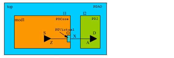
set_design mod1 -honor_boundary_port_domain
create_power_domain -name PDVirtual -boundary_ports O
create_power_domain -name PDCore -default -shutoff_condition en \
   	 -base_domains PDVirtual
end_design
set_design top
create_power_domain -name PDAO default
create_power_domain -name PD2 -shutoff_condition en2 -instances I2
set_instance I1 -design mod1 -domain_mapping {{PDVirtual PDAO}}
end_design
When module mod1 is instantiated at the top, block-level domain PDVirtual is mapped to top-level domain PDAO. Since block mod1 is specified with the -honor_boundary_port_domain option, then at top level, even though the hierarchical pin I1/O has leaf-level driver I1/S/Z in domain I1/PDCore and leaf-level load I2/D/A in domain PD2, the boundary domain association of O with PDAO (due to the domain mapping) should be treated as a design constraint. As a result, the implementation tool may insert a buffer for the top net x within power domain PDAO to meet the design requirement.
Power Mode Control Groups
A power mode control group is a set of power domains with an associated set of power modes and mode transitions that apply to this group only. All power modes defined for this group can only reference power domains within this group. All power mode transitions can only reference power modes defined for this group.
A power domain can belong to more than one power mode control group. However, each power mode control group must have one and only one default power mode.
A power mode group can contain other power mode groups. If a power mode control group has another power mode control group as its member and the other power mode control group is not referenced in any power mode definition, the other power mode control group is assumed to be in the default power mode of that group.
The create_analysis_view command is also extended to be able to create a top-level analysis view by using block-level analysis views created within a power mode control group. This enables the reuse of the block level CPF analysis view. For example, the operating corner assignment for the block-level power domains can be reused at the top level in the implementation flow.
If a power mode control group in a lower scope is not referred to by another power mode or analysis view in an upper scope, the power mode or analysis view at the block level will be ignored at the top level. However, if a power mode control group in a lower scope is referred by some other power mode or analysis view in an upper scope, but not by all, the power mode control group is supposed to be in the default mode in those modes in the upper scope where it is not referenced.
Default Power Mode Control Group
A default power mode control group is automatically created for each CPF scope. The default power mode control group has no name.To reference the default power mode control group of a scope, use the hierarchical path from the current scope to the targeted scope.
The default power mode control group for a scope contains all those power domains defined in this scope that are not declared as members of an explicitly defined power mode control group. In other words, if all power domains of a scope belong to an explicitly defined power mode control group, the default power mode control group has no members.
User-Created Power Mode Control Group
The set_power_mode_control_group and end_power_mode_control_group commands define the start and end of an explicit power mode control group definition.
To declare another power mode control group as a group member of a power mode control group, use the -groups option of the set_power_mode_control_group command.
Within a scope, you can create one or more power mode control groups. A power mode control group can be referenced by its hierarchical name in top-level CPF commands.
A power domain that is not part of any power mode definition within a power mode control group is assumed to be powered down.
Example 5-10 Using Default Power Control Group
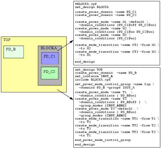
BLOCKA in Example 5-9 is a hierarchical block. The CPF file at the top right defines the power domains, power modes, and power mode transitions for this block. The power modes and power mode transitions are defined with respect to the power domains at this level of hierarchy in the design.
Since no explicit power mode control group is created for BLOCKA, the default power mode control group contains the two power domains of BLOCKA. In this group, power domain PD_C2 is not referenced in mode M3. Therefore, domain PD_C2 is assumed to be in the off state. When the block is instantiated, the hierarchical scope name of the block must be used to refer to the default power mode control group, INST_A in this case.
The CPF file for design TOP has its own power mode control group (top) which includes power domain PD_B and power mode control group INST_A. When defining a power mode for design TOP, you can use the -domain_conditions option for any power domains at this level of hierarchy, but to refer to the power mode of BLOCKA you must use the -group_modes option:
create_power_mode -name T2 -domain_conditions {PD_B@off} -group_modes {INST_A@M2}
In this case, top-level mode T2 is created with domain PD_B at nominal condition off and power mode control group of BLOCKA (INST_A) in power mode M2, in which both block-level domains PD_C1 and PD_C2 are on.
Top-level mode T1 is created with domain PD_B at nominal condition on. Since the power mode control group (INST_A) is not referenced in this top-level mode, it is assumed to be in the default mode of the power mode control group, which is mode M1.
Example 5-11 Use of Explicitly Created Power Mode Control Groups
# from file BLOCKQ.cpf
set_design BLOCKQ
create_power_domain -name PDA1
create_power_domain -name PDA2
create_power_domain -name PDB1
create_power_domain -name PDB2
# PDA1 and PDA2 belong in PMCGA
set_power_mode_control_group -name PMCGA -domains {PDA1 PDA2}
create_power_mode -name MA1 -domain_conditions {PDA1@on PDA2@on } -default
create_power_mode -name MA2 -domain_conditions {PDA1@on PDA2@off}
create_power_mode -name MA3 -domain_conditions {PDA1@off PDA2@on }
create_power_mode -name MA4 -domain_conditions {PDA1@off PDA2@off}
end_power_mode_control_group
# PDB1 and PDB2 belong in PMCGB
set_power_mode_control_group -name PMCGB -domains {PDB1 PDB2}
create_power_mode -name MB1 -domain_conditions {PDB1@on PDB2@on } -default
create_power_mode -name MB2 -domain_conditions {PDB1@on PDB2@off}
create_power_mode -name MB3 -domain_conditions {PDB1@off PDB2@on }
create_power_mode -name MB4 -domain_conditions {PDB1@off PDB2@off}
end_power_mode_control_group
end_design
The power mode control group allows you to concisely specify power modes. In this example, the result of creating two power mode control groups with four power modes each is equivalent to explicitly creating 16 power modes.
Example 5-12 Explicit Power Mode Control Group Hierarchical References
set_design TOP
create_power_domain -name PD1
set_instance INST_Q
include BLOCKQ.cpf
# assumes INST_Q/PMCGA and INST_Q/PMCGB are in the respective default
# power modes (MA1 and MB1)
create_power_mode -name T1 -domain_conditions {PD1@on} -default
# assumes INST_Q/PMCGB is in its default power mode MB1
create_power_mode -name T2 -domain_conditions {PD1@off} \
-group_modes {INST_Q/PMCGA@MA2}
# assumes INST_A/PMCGA is in its default power mode MA1
create_power_mode -name T3 -domain_conditions {PD1@on} \
-group_modes {INST_Q/PMCGB@MB3}
end_design
This example uses the instantiation of BLOCKQ from Example 5-9 and illustrates references to the power mode control groups within BLOCKQ.
Example 5-13 User-Created Power Control Groups with Domains in Multiple Groups
Assume a design with power domains, CPF, GPU, and MEM. The power modes specify a relationship between two out of the three domains: CPF and GPU, CPU and MEM.
To describe the above intent, you can create two power mode control groups, one containing domains CPU and GPU, and one containing domains CPU and MEM. Note that domain CPU belongs to two groups.
set_power_mode_control_group -name PU -groups {CPU GPU}
   	 create_power_mode -name PU_1 -group_modes {CPU@C1 GPU@C2 }
   	 create_power_mode -name PU_2 -group_modes {CPU@C3 GPU@C1 }
end_power_mode_control_group
set_power_mode_control_group -name CMEM -groups {CPU MEM}
   	 create_power_mode -name CMEM_1 -group_modes {CPU@C1 MEM@C2 }
   	 create_power_mode -name CMEM_2 -group_modes {CPU@C3 MEM@C1 }
end_power_mode_control_group
Now, if the current state has CPU@C3, GPU@C1,and MEM@C1, it can be determined that for group PU, the mode is PU_2 and for group CMEM the mode is CMEM_2. Each power mode control group can define the mode transitions and check if the transition is legal. A transition in one group can cause an illegal transition to be reported in another group. For instance, if PU group has a PU_1 to PU_2 transition, and CMEM group does not have a CMEM_1 to CMEM_2 transition, then the CPU domain would go from condition C1 to C3 and an error would be flagged for the CMEM group.