Library Cell-Related CPF Commands
define_always_on_cell
- define_always_on_cell
-
-cells
cell_list[-library_setlibrary_set]- [ {-power_switchable
LEF_power_pin- |-ground_switchable
LEF_ground_pin|-power_switchableLEF_power_pin-ground_switchableLEF_ground_pin}- -power
LEF_power_pin-groundLEF_ground_pin] - [ {-power_switchable
For applications that read .lib files--Identifies the library cells in the .lib files with more than one set of power and ground pins that can remain powered on even when the power domain they are instantiated in is powered down.
For applications that do not read library files--Allows to identify the instances of these cells in the netlist.
Note: The output of these cells is related to the non-switchable power and ground pins.
Options and Arguments
Related Information
define_global_cell
- define_global_cell
-
-cells
cells[-library_setlibrary_set]- [-global_power
pin] [-global_groundpin]- [-local_power
pin] [-local_groundpin]- [-power_off_function {pullup | pulldown | hold }]
- [-isolated_pins
list_of_pin_lists[-enableexpression_list] ] - [-global_power
For applications that read .lib files--Identifies the library cells in the .lib files with more than one set of power and ground pins that can remain functional even when the supplies to the local power and ground pins is switched off.
Note: By default, all input and output pins of this cell are related to the global power and ground pins.
Options and Arguments
Example
The following command defines cell
fooas a global cell. The cell had three isolated pins:pin1,pin2, andpin3. Pinspin1andpin2have the same isolation control signaliso1, butpin3has no isolation control signal.The following command defines cell
AND2_AONas a global cell. The cell has two power pins and performs the AND function as long as the supply connected to power pinVDDis not switched off.
define_isolation_cell
- define_isolation_cell
-
-cells
cell_list[-library_setlibrary_set]- [-always_on_pins
pin_list]- [-aux_enables
pin_list]- [-power_switchable
LEF_power_pin] [-ground_switchableLEF_ground_pin]- [-power
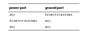
LEF_power_pin] [-groundLEF_ground_pin]- [-valid_location {from | to | on | off | any}]
- { -enable
pin[-clamp {high|low}]- | -pin_groups
group_list| -no_enable {high|low|hold} }- [-non_dedicated]
- [-always_on_pins
For applications that read .lib files--Identifies the library cells in the .lib files that must be used as isolation cells.
For applications that do not read library files--Allows to identify the instances of isolation cells in the netlist.
Note: By default, the output pin of a multi-power rail isolation cell is related to the non-switchable power and ground pins. The non-enable input pin is related to the switchable power and ground pins.
Options and Arguments
Examples
The following isolation cell can be placed in any location for a design that uses ground switches for power shutoff. VDD is the followpin for power connection and GVSS is the ground pin for global ground connection
The following examples illustrate the use of the
-pin_groupsoption to specify multi-bit isolation cells with two paths:
Related Information
Modeling Isolation Cells in the Common Power Format User Guide
define_level_shifter_cell
- define_level_shifter_cell
-
-cells
cell_list[-library_setlibrary_set]- [-always_on_pins
pin_list]{ -input_voltage_rangevoltage_list|voltage_range_list}-output_voltage_rangevoltage_list|voltage_range_list}- | -ground_input_voltage_range {
voltage_list|voltage_range_lsit}- -ground_output_voltage_range {
voltage_list|voltage_range_list}- |
-input_voltage_rangevoltage_list|voltage_range_list}-output_voltage_rangevoltage_list|voltage_range_list}- -ground_input_voltage_range {
voltage_list|voltage_range_list}- -ground_output_voltage_range {
voltage_list|voltage_range_list} }- [-direction {up|down|bidir}]
- [-input_power_pin
LEF_power_pin]LEF_power_pin]- [-input_ground_pin
LEF_ground_pin]- [-output_ground_pin
LEF_ground_pin]- [-ground
LEF_ground_pin]LEF_power_pin]- [-enable
pin| -pin_groups { {input_pin output_pin[enable_pin] }... }]- [-valid_location {to | from | either | any}]
- [-bypass_enable
expression] [-multi_stageinteger] - [-always_on_pins
For applications that read .lib files--Identifies the library cells in the .lib files that must be used as level shifter cells.
For applications that do not read library files--Allows to identify the instances of level shifter cells in the netlist.
 | If you specify a list of voltages or ranges for the input supply voltage, you must also specify a list of voltages or voltage ranges for the output supply voltage. Both lists must be ordered and have the same number of elements. That is, each member in the list of input voltages (or ranges) has a corresponding member in the list of output voltages (or ranges). |
Note:
By default, the enable and output pins of this cell are related to the output power and output ground pins (specified through the -output_power_pin and -output_ground_pin options). The non-enable input pin is related to the input power and input ground pins (specified through the -input_power_pin and -input_ground_pin options).
Options and Arguments
Specifies a list of cell pins which must always be driven. Note: A pin specified with this option, can be specified with other options as well. |
|
Specifies the condition when to bypass the voltage shifting functionality.
When the expression evaluates to The expression must be a simple expression of the bypass enable input pin. |
|
Identifies any specified cell as a level shifter. The libraries loaded will be searched and all cells found will be used. |
|
Specifies whether the level shifter can be used between a lower and higher voltage, or vice versa. |
|
Identifies the pin that prevents internal floating when the power supply of the source power domain is powered down but the output voltage level power pin remains on. Note: Cells that have this type of pin can be used for isolation purposes. |
|
Identifies the name of the Note: This option can only be specified for level shifters that only perform power voltage shifting. |
|
|
|
Identifies either a single voltage, single voltage range, or list of voltages or ranges for the input (source) ground supply voltage that can be handled by this level shifter. The voltage range must be specified as follows:
Specify the lower bound, upper bound and voltage increment step, respectively. The voltage increment can be optional. Note: This option should only be specified for ground voltage shifting. |
|
|
|
Identifies either a single voltage, single voltage range, or list of voltages or ranges for the output (destination) ground supply voltage that can be handled by this level shifter. The voltage range must be specified as follows:
Specify the lower bound, upper bound and voltage increment step, respectively. The voltage increment can be optional. Note: This option should only be specified for ground voltage shifting. |
|
Identifies the name of the Note: This option is usually specified for ground voltage shifting. |
|
Identifies the name of the Note: This option is usually specified for power voltage shifting. |
|
Identifies either a single voltage, single voltage range, or list of voltages or ranges for the input (source) power supply voltage that can be handled by this level shifter. The voltage range must be specified as follows:
Specify the lower bound, upper bound and voltage increment step, respectively. The voltage increment can be optional. Note: This option should only be specified for power voltage shifting. |
|
References the library set to be used to search for the specified cells. Specify the library set name. All matching cells will be used. If you omit this option, all library sets are searched and all matching cells will be used.
The libraries must have been previously defined in a |
|
Identifies the stage of a multi-stage level shifter to which this definition (command) applies. For a level shifter cell with N stages, N definitions must be specified for the same cell. Each definition must associate a number from 1 to N for this option. For more information, see Modeling Level Shifters. |
|
Identifies the name of the Note: This option is usually specified for ground voltage shifting. |
|
Identifies the name of the Note: This option is usually specified for power voltage shifting. |
|
Identifies either a single voltage, single voltage range, or list of voltages or ranges for the output (destination) power supply voltage that can be handled by this level shifter. The voltage range must be specified as follows:
Specify the lower bound, upper bound and voltage increment step, respectively. The voltage increment can be optional. Note: This option should only be specified for power voltage shifting. |
|
Specifies a list of input-output paths for multi-bit cells. Each group in the list specifies one cell input pin, one cell output pin, and one optional enable pin that applies to the specified path. Use the following format for each group in the list:
An enable pin may appear in more than one group. It is an error if the same input or output pin appears in more than one group. |
|
Identifies the name of the Note: This option can only be specified for level shifters that only perform ground voltage shifting. |
|
Specifies the location of the level shifter cell. Possible values are: |
|
|
|
| |
|
Examples
The following command identifies level shifter cells with one power pin and one ground pin that perform power voltage shifting from 1.0V to 0.8V:
define_level_shifter_cell \
-cells LSHL* \-input_voltage_range
-direction down \
-output_power_pin VL -ground GThe following command identifies level shifter cells that perform power voltage shifting from 0.8V to 1.V. In this case, the level shifter cells must have two power pins and one ground pin.
define_level_shifter_cell \
-cells LSLH* \-input_voltage_range
-direction up \
-input_power_pin VL -output_power_pin VH -ground GThe following command identifies level shifter cells that perform both power voltage shifting from 0.8V to 1.V and ground voltage shifting from 0.5V to 0V. In this case, the level shifter cells must have two power pins and two ground pins.
define_level_shifter_cell \
-cells LSLH* \-input_voltage_range
-groun_input_voltage_range 0.5 -ground_output_voltage_range 0.0
-direction up \
-input_power_pin VL -output_power_pin VH \
-input_ground_pin GH -output_ground_pin GLThe following command indicates that the level shifter can shift from 0.8 to 1.0 or from 1.0 to 1.2.
define_level_shifter_cell \
-cells LSHL* \-input_voltage_range
-direction upThe following command indicates that the level shifter can shift from input range 0.8 to 0.9 to output range 1.0 to 1.1, or from input range 1.0 to 1.1 to output range 1.2 to 1.3.
define_level_shifter_cell \
-cells LSHL* \-input_voltage_range
-output_voltage_range {1.0:1.1 1.2:1.3} \
-direction upThe following examples illustrate the use of the
-pin_groupsoption to specify multi-bit level shifter cells:
Related Information
Modeling Level Shifters in the Common Power Format User Guide
define_open_source_input_pin
- define_open_source_input_pin
-
-cells
cell_list-pinpin[-library_setlibrary_set]- [-type {nmos|pmos|both}]
Specifies a list of cells that contain open source input pins. You can use this command within a macro model to specify which input pin of the macro cell is open source.
These are input pins that must be isolated when the power supply of the driver is on, but the power supply of the cells to which the input pin belongs is shut off.
Options and Arguments
define_pad_cell
- define_pad_cell
-
-cells
cell_list-pad_pinspin_list- [-isolated_pins
list_of_pin_lists[-enableexpression_list]]- [-pin_groups
pin_group_list] [-analog_pinspin_list] - [-isolated_pins
Identifies a list of library cells in the .lib files that are simple pad cells.
Note: This can be used by tools that do not read .lib to identify a pad cell.
Options and Arguments
Related Information
Modeling a Pad Cell in the Common Power Format User Guide
define_power_clamp_cell
- define_power_clamp_cell
-
-cells
cell_list-datapin-powerpin[-groundpin_name][-library_setlibrary_set]
Specifies a list of diode cells used for power clamp control.
Options and Arguments
define_power_clamp_pins
- define_power_clamp_pins
-
-cells
cell_list-data_pinspin_list{ [-type power] -powerpin[-groundpin]- | -type ground -ground
pin[-powerpin]- | -type both -power
pin-groundpin}- [-library_set
library_set]
Identifies a list of library cells that are either power, ground, or power and ground clamp cells, or complex cells that have input pins with built-in clamp diodes.
Options and Arguments
define_power_switch_cell
- define_power_switch_cell
-
-cells
cell_list[-library_setlibrary_set]- -stage_1_enable
expression[-stage_1_outputexpression]- [-stage_2_enable
expression[-stage_2_outputexpression]]- -type {footer|header}
- [ -enable_pin_bias [
float:]float] [ -gate_bias_pinLEF_power_pin]- [ -power_switchable
LEF_power_pin-powerLEF_power_pin| -ground_switchableLEF_ground_pin-groundLEF_ground_pin]- [ -stage_1_on_resistance
float[-stage_2_on_resistancefloat]]- [ -stage_1_saturation_current
float] [ -stage_2_saturation_currentfloat]- [ -leakage_current
float] - -stage_1_enable
For applications that read .lib files--Identifies the library cells in the .lib files that must be used as power switch cells.
For applications that do not read library files--Allows to identify the instances of power switch cells in the netlist.
Note: The input enable and output enable pins of this cell are related to the non-switchable power and ground pins.
Note:
This command is required if you use the create_power_switch_rule command.
Options and Arguments
Examples
The following command defines a header power switch. The power switch has two stages. The power switch is completely on if the transistors of both stages are on. The stage 1 transistor is turned on by applying a low value to input
I1.The output of the stage 1 transistor,O1, is a buffered output of input I1. The stage 2 transistor is turned on by applying a high value to inputI2. The output of stage 2 transistor,O2, is the inverted value of inputI2.define_power_switch_cell -cells 2stage_switch -stage_1_enable !I1 \
-stage_1_output O1 -stage_2_enable I2 -stage_2_output !O2 -type headerAssume that a power switch is connected to a power supply of 1.0V. The following command indicates that the enable pin of the power switch cell can be driven by signal of up to 1.2 V.
Related Information
Modeling Power Switch Cells in the Common Power Format User Guide
define_related_power_pins
- define_related_power_pins
-
-data_pins
pin_list- -cells
cell_list[-library_setlibrary_set]- {-power
LEF_power_pin| -groundLEF_ground_pin- | -power
LEF_power_pin-groundLEF_ground_pin} - -cells
Specifies the relationship between the power pins and data pins for cells that have more than one set of power and ground pins.
Note:
You can also use this command to overwrite the default power pin and data pin association in special low power cells defined through the define_xxx_cell commands.
Options and Arguments
define_state_retention_cell
- define_state_retention_cell
-
-cells
cell_list[-library_setlibrary_set]- [-cell_type
string]- [-always_on_pins
pin_list][-clock_pinpin]{-restore_functionexpression| -save_functionexpression|-restore_functionexpression-save_functionexpression}- [-restore_check
expression] [-save_checkexpression]- [-retention_check
expression]- [-always_on_components
component_list]- [ {-power_switchable
LEF_power_pin- |-ground_switchable
LEF_ground_pin|-power_switchableLEF_power_pin-ground_switchableLEF_ground_pin}- -power
LEF_power_pin-groundLEF_ground_pin] - [-cell_type
For applications that read .lib files--Identifies the library cells in the .lib files that must be used as state retention cells.
For applications that do not read library files--Allows to identify the instances of state retention cells in the netlist.
Note: In what follows, power refers to the switchable power or ground in the cell. The non-switchable power and ground must be on for the cell to operate properly.
To model a retention cell with only one retention control, you can specify either -save_function or -restore_function.
If you specify
-save_function, the cell saves the current value when the expression changes fromfalsetotrueand the power is on. The cell restores the saved value when the power is turned on.If you specify
-restore_function, the cell saves the current value when the expression changes fromtruetofalseand the power is on. The cell restores the saved value when the expression changes fromfalsetotrueand the power is on.
To model a retention cell with both save and restore control, both options must be specified. In this case, the cell saves the current value when the save expression is true and the power is on. The cell restores the saved value when the restore expression is true and the power is on.
It is an error if you use the same pin or same expressions for both the save and restore function. For example the following two commands are not correct:
define_state_retention_cell -cells My_Cell -restore_function pg -save_function !pg
define_state_retention_cell -cells foo -restore_function pg -save_function pg
Note: By default, all pins of this cell are related to the switchable power and ground pins unless otherwise specified.
Options and Arguments
Example
In the following example, clock
clkmust be held to0to save or restore the state of the sequential element. If power gating pinpgis set to 0, the state will be saved. If restore pinmy_restoreis set to1, the state will be restored.define_state_retention_cell -cells My_Cell -power VDDC \
-ground VSS -power_switchable VDD -restore_function "my_restore" \
-restore_check "!clk" -save_function "!pg"The following example shows how to model a master-slave type state retention cell ( a state retention cell that does not have a save or restore control pin). The clock signal acts as the retention control signal.
Related Information
Handling Master-Slave Type Retention Cells
Modeling State Retention Cells in the Common Power Format User Guide