3
The Spectre APS Circuit Simulator
In addition to the baseline simulation functionalities, Spectre supports the APS technology that provides significant performance gain and simulation capacity over the baseline Spectre simulation with minimum or no accuracy degradation.
The Spectre® APS technology contains newer and better performance technologies to further speed up device evaluation, particularly speeding up the matrix solving part of computation that often dominates large and postlayout circuit simulation.
The Spectre APS technology supports multithreading on multi-core computer platforms.
This chapter discusses the following:
- Starting Spectre APS Simulations
- Getting More Performance from Spectre APS Simulation
- Specifying Multithreading Options
- Simulation Diagnostics
- Spectre Mixed-Signal Design Simulation
Starting Spectre APS Simulations
To start a Spectre APS simulation, type the following at the command line:
% spectre +aps commandline_options ...
You can specify an errpreset value with the +aps command-line option to override the errpreset value in all transient analyses in the netlist. When the errpreset value is not specified with the +aps command-line option, the errpreset value in the analysis statement is used.
For more information on the errpreset parameter, see The errpreset Parameter.
To run Spectre baseline:
% spectre [+errpreset=liberal | moderate | conservative …] input.scs
To run Spectre with APS:
% spectre +aps[=liberal|moderate|conservative] netlist
% spectre +aps [+errpreset=liberal|moderate|conservative] netlist
Example
% spectre +aps=liberal adc.scs
In the above example, Spectre APS is launched using the liberal setting.
Getting More Performance from Spectre APS Simulation
Spectre APS uses identical simulation algorithms (numerical tolerance control, time step control, Newton iteration control, analytical device model, and so on) as baseline Spectre. It is designed to produce identical simulation results as baseline Spectre. Spectre is known to focus and produce accurate simulation results. Spectre APS preserves all of these numerical simulation algorithms and it is expected to produce a near identical simulation numerical noise floor as baseline Spectre. This tight accuracy correlation between baseline Spectre and Spectre APS does restrict some additional simulation performance.
To further speed up simulation, you can use the ++aps simulation mode. The ++aps simulation mode has exactly the same use model and simulation feature coverage as default Spectre APS. You can start a ++aps simulation, as follows:
% spectre ++aps ...
++aps supports the same errpreset parameters and uses the same numerical tolerance controls as baseline Spectre and Spectre APS. However, it is not restricted to use the same time step and Newton iteration control algorithms. The ++aps simulation produces a similar simulation numerical noise floor as baseline Spectre and Spectre APS.
Postlayout simulation often poses a severe simulation performance challenge. It makes DC analysis difficult to converge and transient simulation much longer to complete. There are many numerical techniques available in Spectre to address these challenges, such as parasitic RC reduction, effective and accurate coupling capacitor handling, and specific DC algorithm for postlayout simulation. A simple +postlayout command-line option is available in Spectre for maximizing postlayout simulation performance. You can start a Spectre APS simulation on a postlayout design, as shown below.
% spectre ++aps +postlayout ...
To speed up the transient simulation for circuits containing a large number of mutual inductors, use the +lopt command-line option, as shown below.
% spectre +aps +lopt...
Circuit simulation performance is directly related to the core simulation engine, but often can be heavily skewed due to certain computationally intensive simulation features, such as device checking asserts, and large amount of current and power probing. To assist simulation performance debugging, a lightweight (+lite) simulation setting that automatically strips away all of these computationally intensive peripheral simulation features is available. You can enable the lightweight simulation, as follows:
% spectre +aps +lite ...
To improve the simulation accuracy of high-voltage circuits (where the maximum voltage is greater than 10 volts), or circuits that have convergence issues and report large capacitance values in the log file, you can set the highvoltage parameter in the options statement to yes.
opt1 options highvoltage=yes
Use this option with moderate/liberal mode, if the original simulation needs conservative mode to get accurate results.
Designs having different ground voltages may have an impact on the simulation accuracy. You can use the vrefgnd parameter in the options statement to make the default simulation tolerance criteria same for such designs. For example:
Opt options vrefgnd=gnd_node_name subckt=[sub1]
Opt options vrefgnd=gnd_node_name inst=[sub_inst1]
Specifying Multithreading Options
Spectre baseline, Spectre APS, Spectre X, and Spectre XPS S-mode technologies support multi-threaded computation on multi-core computer platforms. Spectre APS/XPS and Spectre X have better multithreading scaling compared to Spectre baseline technology.
The default settings for multithreading are given below:
To turn off multithreading, use the following commands:
% spectre -mt ...
% spectre +aps -mt ...
To turn on the multithreading feature in baseline Spectre, use the following command:
% spectre +mt ...
There is no need to specify +mt for Spectre APS run because multithreading is on by default.
To manually specify the number of threads to be used, instead of the default threads, use the following command:
% spectre +mt=4 ...
% spectre +aps +mt=4 ...
% spectre +preset=ax +mt=4...
% spectre +xps=s +mt=4 ...
Spectre supports various computer farm management tools, such as LSF, Sungrid engine, NetworkComputer, LoadLeveler, and netbatch with the following statement:
% spectre +aps +mt=lsf | sge | nc | loadleveler | farm | netbatch...
where the Spectre session will use the number of cores allocated by the farm tools.
To benefit from multithreading technology, a circuit should have at least 250 devices. When a circuit is too small, the multithreading option is turned off automatically.
Using the query Option
The +query command-line option with possible values of mtinfo, meminfo, all, alllic, and tokenlic (default) enables you to get an estimate of the number of threads or licenses required to run a simulation without actually running the simulation.
-
mtinfo- prints the recommended number of threads required to run the simulation in a multi-threaded environment. -
meminfo- prints an estimate of the memory that would be required to run a design -
all- prints both the number of threads and the estimate of memory that would be required to run a design. -
alllic- prints all possible combination of licenses required to run a design. -
tokenlic- prints the number of Spectre MMSIM tokens required to run the design.
% spectre +query=mtinfo +aps input.scs.....
Simulation Diagnostics
At times, you need additional debugging information to investigate the performance or convergence-related simulation issues. By default, the simulation log file now contains a pre-simulation summary and a post-transient simulation summary with suggestions on how to speed up the simulation further. In addition, you can use the Spectre command-line option, +diagnose, to dump additional debugging information into the simulation log file. The following is an example of using the +diagnose option:
% spectre +aps +diagnose input.scs
The +diagnose option automatically enables the AHDL linter feature, and outputs the following additional information to the log file:
-
Convergence-related information for time steps less than 1ps. This can be controlled by using the
warnminstepoption. - A summary containing statistics about time steps, nodes with convergence issues, and node or device activity information.
+diagnose option has minimal impact on the simulation time, however, it generates a lot of information and may not be appropriate for general use.Spectre Mixed-Signal Design Simulation
The Spectre Mixed-Signal (MS) simulation mode delivers a high-performance transistor-level multi-rate simulation solution by combining a highly accurate SPICE engine (Spectre APS) together with a fast digital simulation engine (Spectre XPS). The identification between the analog and digital portions of the circuit is done automatically, with the added flexibility for advanced users to optimize it.
Spectre MS is fully integrated into the Spectre binary sharing the same product infrastructure with Spectre, Spectre APS, Spectre X, and Spectre XPS. The use model is identical to that of Spectre, with the netlist syntax, device models, analysis setups, and output formats being fully compatible.
Spectre MS speeds up both pre-layout and postlayout simulations. The supported postlayout simulation flows are: Virtuoso extracted view, included DSPF, backannotated DSPF/SPEF, and flat postlayout SPICE and Spectre netlist files.
Spectre MS supports most Spectre transient features including save, ic, nodeset, measure, vec/vcd, asserts, static design checks, selective dynamic design checks, RC reduction, and EMIR. It also supports dynamic parameters. However, dynamic parameters are supported only for the analog partition (APS). For more information on dynamic parameters, refer to the Transient Analysis section in the Spectre Circuit Simulator Reference manual.
Advanced simulation features, such as info, alter, device reliability, and montecarlo are currently not supported, however, support for these features may be added incrementally in future releases.
Starting an Spectre MS Simulation Run
You can invoke the MS mode using the Spectre binary with the following command:
% spectre +ms input.scs …
You can specify the errpreset setting at the command line, with +aps=liberal being the default setting.
When the MS mode is enabled, a message is displayed in the log file stating the same.
When using a SPICE runset, add the +spice option to ensure that the netlist convention and device models are interpreted in a consistent manner as traditional SPICE, instead of Spectre.
The MS mode supports multithreading on multicore machines. The multithreading use model and behavior are identical to Spectre APS.
Adjusting MS Speed and Accuracy
The Spectre MS mode supports all performance and accuracy settings of Spectre APS for the analog portion simulation. The default errpreset setting is liberal, which is sufficient for the functional verification of most mixed-signal designs.
The simulation speed and accuracy of digital portions in the MS mode can be controlled by the command-line option speed=0/1/2/3. The default value is 2, which is sufficient for most applications. Use speed=0 for more accurate timing and power simulation of digital portions. speed=1 is a little faster than speed=0. Use speed=3 for fastest digital verification, however, this may have an impact on accuracy.
The following example shows the combination of analog options (++aps=liberal) with digital options (speed=3):
% spectre +ms ++aps=liberal +speed=3 input.scs
Digital Partitioning and Virtual Power Nodes
The Spectre MS mode automatically detects the digital functions in a given circuit. For cases where a design has explicit hierarchical digital or analog functions, you can manually identify the functional blocks (subcircuit, instance) by using the following Spectre options:
optD options cktpreset=digital subckt=[dig_ctrl pll]
optA options cktpreset=analog subckt=[opamp adc]
optD options cktpreset=digital inst=[x1.xdig_ctrl x1.xpll]
optA options cktpreset=analog inst=[x2.xopamp x2.xadc]
.options cktpreset=digital subckt=[dig_ctrl pll]
.options cktpreset=analog subckt=[opamp adc]
.options cktpreset=digital inst=[x1.xdig_ctrl x1.xpll]
.options cktpreset=analog inst=[x2.xopamp x2.xadc]
Digital detection works seamlessly for digital circuitry with ideal DC power supplies or identified virtual power supplies. The MS mode not only detects the virtual power supplies (that is, internal VDD generator) in the design automatically, but also provides the flexibility to define the virtual power supply nodes manually. The log file provides information on the nodes that are identified as power/ground supplies and other nodes that are potential power/ground supplies. A sample log file report is shown below.
Digital Detection Vsource and Virtual Power Supply Node Summary
For the detected nodes, the table reports the node type, the number of channel connections (#CC), the number of bulk connections (#Bulk), the node voltage, and the node name. The following node types are reported:
- GND - ground node.
- VSOURCE - ideal power supply node.
- VPN - virtual power supply node
- VGND - virtual ground node.
- Possible - potential power/ground supplies
Nodes of type GND, VSOURCE, VPN, and VGND are used as power supply and ground nodes when detecting digital circuitry. The Possible type refers to potential power/ground supplies that are not used for digital circuit detection.
You can define the virtual power supply nodes manually by using the ms_vpn option that defines the pairs of node names (wildcard is supported) and voltage values. The virtual ground nodes can be defined using the ms_vgnd option. The ground voltage is assumed to be 0V.
opt1 options ms_vpn = [I1.VDD_DIG 1.8 I1.VDD_DIG1 3.3]
opt3 options ms_vgnd = [I1.VSS]
.options ms_vpn = [I1.VDD_DIG 1.8 I1.VDD_DIG1 3.3]
.options ms_vgnd = [I1.VSS]
If required, you can define the global virtual power supply voltage by using the ms_vpnv option, as shown below.
opt2 options ms_vpnv = 1.2
.options ms_vpnv = 1.2
The default global value is 1.8V.
In case the virtual power supply voltage is not known, you can use the auto_vpn option to enable Spectre to detect the voltage automatically, as shown below.
opt4 options ms_vpn = [I1.VDD_DIG auto_vpn I1.RF_VDD auto_vpn]
.options ms_vpn = [I1.VDD_DIG auto_vpn I1.RF_VDD auto_vpn]
The maximum voltage for the device models in the digital simulation engine is detected automatically. If required, it can be set using the vdd option, as shown below.
opt4 options vdd = 1.8
Spectre MS DC Operating Point Calculation
The Spectre MS mode calculates the DC operating point before performing the transient simulation. By default, the DC operating point for the entire circuit is calculated by Spectre APS (+msdc=aps). For cases where the Spectre APS operating point calculation takes too long, you can enable the mixed-signal DC calculation – Spectre APS for the analog partition and Spectre XPS for the digital partition, by using the +msdc=ms command-line option, as shown below.
% spectre +ms +msdc=aps input.scs
The above command calculates the DC operating point using Spectre APS.
% spectre +ms +msdc=ms input.scs
The above command enables the mixed-signal DC calculation.
Spectre MS Current Accuracy
When using ideal or strong virtual power supplies, Spectre MS mode properly calculates the current consumption based on the active and leakage currents of all driven analog and digital blocks.
However, when the virtual power supplies are weak, the following time window-based options may be used to obtain accurate current values:
opt1 options ms_vpni_start=1u ms_vpni_stop=10u
Since these options significantly impact the simulation performance, it is recommended to define the time window as small as possible. In addition, it is recommended not to enable these options during the ramp-up period.
Handling Macro Device Models
The Spectre MS mode, by default, effectively recognizes device models including BSIM3V3, BSIM4, BSIMCMG, BSIMSOI, PSP, and so on. Device recognition enables digital detection that is critical to ensure that the Spectre MS mode gets the best possible simulation performance. Even complicated device macro models with more than four terminals and additional elements (resistors, capacitors, parasitic diodes, parasitic BJT's) are automatically handled, if the first four terminals are the primary MOSFET d g s b terminals.
Complex elements with Verilog-A, behavior source (bsource), or multiple MOSFET elements inside require you to explicitly define the name of the macro model subcircuit, as follows:
opt1 options macro_mos=[mos1 mos2]
.options macro_mos=[mos1 mos2]
Here, mos1 and mos2 are subcircuit definition names for macro device models.
If the first four terminals of the macro model are not d g s b, then the default macro model handling does not work. The required port detection and handling for such macro models can be enabled with the following option:
opt1 options macro_mos_wrapper=yes
.options macro_mos_wrapper=yes
Spectre MS Postlayout Simulation
The Spectre MS mode supports different postlayout simulation flows (Virtuoso extracted view, included DSPF files, and flat postlayout SPICE and Spectre netlist files), as well as DSPF/SPEF backannotation.
Non-backannotation Postlayout Simulation Flow
You can enable the Spectre MS postlayout simulation by using the +postlayout command-line option, as follows:
spectre +ms +postlayout input.scs
The flow automatically enables RC reduction, optimized RC element handling, and DC algorithms. You can set RC reduction in the analog portion simulation to be more conservative (+postlayout=hpa).
spectre +ms +postlayout=hpa input.scs
DSPF/SPEF Backannotation
The alternative DSPF/SPEF backannotation flow is enabled with the DSPF/SPEF backannotation options. This flow does not require the +postlayout command-line option.
Opt1 options spf=”I1 pll.spf
Opt2 options spef=”I1 pll.spef
.options spf=”I1 pll.spf
All RC backannotation-related Spectre options, such as spfscale, spfxtorprefix, and spfaliasterm are supported. If RC reduction is required, it can be enabled as part of the backannotation process (spfrcr, spfrcrfmax). For more information on these options, refer to Parsing Options Used in Backannotation.
The Spectre MS logfile provides two backannotation reports. The first report summarizes the RC elements backannotated to the digital partitions, while the second report summarizes the RC elements backannotated to the analog partitions.
When using Spectre MS for postlayout designs, +speed=3 is not recommended. For accuracy comparison, Spectre APS without RC reduction is recommended as the golden reference. The performance of Spectre XPS with +postlayout should be compared against Spectre APS with +postlayout.
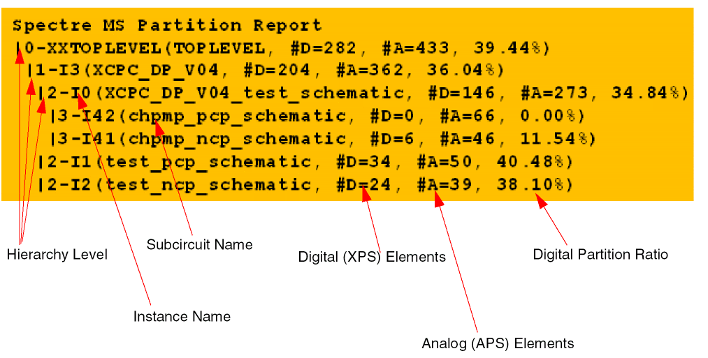
Spectre MS Partitioning Report
Spectre MS provides the ability to print a partitioning report. The report provides information about the analog and digital portions of each subcircuit instance with more than 50 elements.
To print the partitioning report, use the ms_part_report=depth option as follows:
opt1 options ms_part_report=10
Here, depth is the hierarchical depth counted from top level (depth=0). The partition report is written to a file named partition_<netlist>.rpt.
The following is an example of the partitioning report:
Return to top